EP0627739B1 - Appareil d'enregistrement/de reproduction pour support en forme de disque - Google Patents
Appareil d'enregistrement/de reproduction pour support en forme de disque Download PDFInfo
- Publication number
- EP0627739B1 EP0627739B1 EP94303722A EP94303722A EP0627739B1 EP 0627739 B1 EP0627739 B1 EP 0627739B1 EP 94303722 A EP94303722 A EP 94303722A EP 94303722 A EP94303722 A EP 94303722A EP 0627739 B1 EP0627739 B1 EP 0627739B1
- Authority
- EP
- European Patent Office
- Prior art keywords
- display
- disc
- data
- recording
- cartridge
- Prior art date
- Legal status (The legal status is an assumption and is not a legal conclusion. Google has not performed a legal analysis and makes no representation as to the accuracy of the status listed.)
- Expired - Lifetime
Links
- 238000001514 detection method Methods 0.000 claims description 27
- 238000006243 chemical reaction Methods 0.000 claims description 2
- 239000011159 matrix material Substances 0.000 claims description 2
- 230000000007 visual effect Effects 0.000 claims 1
- 230000003287 optical effect Effects 0.000 description 182
- 230000006870 function Effects 0.000 description 9
- 230000005236 sound signal Effects 0.000 description 8
- 238000010586 diagram Methods 0.000 description 4
- 239000000284 extract Substances 0.000 description 4
- 238000013479 data entry Methods 0.000 description 3
- 238000013075 data extraction Methods 0.000 description 3
- 101100365087 Arabidopsis thaliana SCRA gene Proteins 0.000 description 2
- 230000005540 biological transmission Effects 0.000 description 2
- 230000012447 hatching Effects 0.000 description 2
- 230000004044 response Effects 0.000 description 2
- 238000004088 simulation Methods 0.000 description 2
- 239000003086 colorant Substances 0.000 description 1
- 230000004927 fusion Effects 0.000 description 1
- 239000007788 liquid Substances 0.000 description 1
- 239000004973 liquid crystal related substance Substances 0.000 description 1
- 239000011435 rock Substances 0.000 description 1
Images


Classifications
-
- H—ELECTRICITY
- H04—ELECTRIC COMMUNICATION TECHNIQUE
- H04S—STEREOPHONIC SYSTEMS
- H04S1/00—Two-channel systems
-
- G—PHYSICS
- G11—INFORMATION STORAGE
- G11B—INFORMATION STORAGE BASED ON RELATIVE MOVEMENT BETWEEN RECORD CARRIER AND TRANSDUCER
- G11B20/00—Signal processing not specific to the method of recording or reproducing; Circuits therefor
- G11B20/00992—Circuits for stereophonic or quadraphonic recording or reproducing
-
- G—PHYSICS
- G11—INFORMATION STORAGE
- G11B—INFORMATION STORAGE BASED ON RELATIVE MOVEMENT BETWEEN RECORD CARRIER AND TRANSDUCER
- G11B27/00—Editing; Indexing; Addressing; Timing or synchronising; Monitoring; Measuring tape travel
- G11B27/002—Programmed access in sequence to a plurality of record carriers or indexed parts, e.g. tracks, thereof, e.g. for editing
-
- G—PHYSICS
- G11—INFORMATION STORAGE
- G11B—INFORMATION STORAGE BASED ON RELATIVE MOVEMENT BETWEEN RECORD CARRIER AND TRANSDUCER
- G11B27/00—Editing; Indexing; Addressing; Timing or synchronising; Monitoring; Measuring tape travel
- G11B27/10—Indexing; Addressing; Timing or synchronising; Measuring tape travel
- G11B27/34—Indicating arrangements
-
- G—PHYSICS
- G11—INFORMATION STORAGE
- G11B—INFORMATION STORAGE BASED ON RELATIVE MOVEMENT BETWEEN RECORD CARRIER AND TRANSDUCER
- G11B31/00—Arrangements for the associated working of recording or reproducing apparatus with related apparatus
-
- G—PHYSICS
- G11—INFORMATION STORAGE
- G11B—INFORMATION STORAGE BASED ON RELATIVE MOVEMENT BETWEEN RECORD CARRIER AND TRANSDUCER
- G11B33/00—Constructional parts, details or accessories not provided for in the other groups of this subclass
- G11B33/10—Indicating arrangements; Warning arrangements
-
- G—PHYSICS
- G11—INFORMATION STORAGE
- G11B—INFORMATION STORAGE BASED ON RELATIVE MOVEMENT BETWEEN RECORD CARRIER AND TRANSDUCER
- G11B20/00—Signal processing not specific to the method of recording or reproducing; Circuits therefor
- G11B20/10—Digital recording or reproducing
- G11B20/10527—Audio or video recording; Data buffering arrangements
- G11B2020/10537—Audio or video recording
- G11B2020/10592—Audio or video recording specifically adapted for recording or reproducing multichannel signals
-
- G—PHYSICS
- G11—INFORMATION STORAGE
- G11B—INFORMATION STORAGE BASED ON RELATIVE MOVEMENT BETWEEN RECORD CARRIER AND TRANSDUCER
- G11B2220/00—Record carriers by type
- G11B2220/20—Disc-shaped record carriers
- G11B2220/25—Disc-shaped record carriers characterised in that the disc is based on a specific recording technology
- G11B2220/2537—Optical discs
- G11B2220/2545—CDs
Definitions
- This invention relates to a recording and/or reproducing apparatus for a disc-shaped recording medium. More particularly, it relates to a recording and/or reproducing apparatus for a disc-shaped recording medium, and a sound reproducing apparatus, in which information signals may be recorded on or reproduced from one of plural disc-shaped recording media.
- optical disc reproducing apparatus has become popular in addition to the cassette decks or tuners, and are being diversified in their functions.
- the optical disc reproducing apparatus includes a magazine capable of containing plural optical discs.
- EP 0 453 064 discloses a multi-disc player which displays a table listing the titles of discs held.
- a magazine 201 of such changer capable of containing six optical discs D therein, as shown in Fig.1, is configured to accommodate six optical discs D so that the planar surfaces of the discs D lie horizontally with a vertical clearance from one another.
- the discs D are termed the first, second, and so forth, up to the sixth as counted from the bottom to the uppermost side.
- the changer includes an operating panel for realizing a variety of operations, such as the playback operation or the optical disc selecting operation, and a display unit for listing the number or the title of the discs D contained in the changer.
- the list display configuration is shown in Fig.2, in which the discs D are indicated as "1", “2", ⁇ "6" as counted from the uppermost side, thus in the reverse order to the arraying order of the discs D in the magazine, and the title of the optical disc bearing the associated number is also displayed.
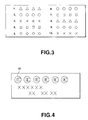
- the display is made in five rows in two columns, owing to the constraint in the display area of the display unit, as shown in Fig.3.
- the left column is numbered 1 to 5, while the right column is numbered 6 to 10, and the title concerning the optical disc bearing the disc number is also displayed.
- the number of the optical disc being reproduced is displayed in a unique color, or the number and the title of the disc are displayed with brightness inversion.
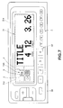
- Fig.4 shows another conventional display configuration for the display unit, according to which a number of marks M corresponding to the number of the optical discs D loaded in the changer magazine are displayed in a sole transverse row at an upper portion of the display area.
- serial numbers are affixed to the marks so that the number of the loaded discs can be grasped easily.
- the numbers of the marks for the discs not loaded in the magazine remain unlighted so that the state of loading of the discs in the magazine 201 can be grasped easily.
- the arraying order of the optical discs D in the magazine 201 shown in Fig.l does not correspond to the list display sequence shown in Fig.2. Consequently, when a given optical disc D loaded in the magazine 201 is exchanged with another optical disc, the arraying sequence in the magazine 201 is different from the list display sequence on the display unit. Consequently, in effecting the disc exchange, the list display sequence needs to be checked in association with the arraying sequence in the magazine 201 by a laborious operation.
- the optical disc D to be displayed is directly selected using a ten-key provided on the operating panel.
- a remote control switch for example, is used for performing the disc selecting operation.
- the conventional switch of this kind is mainly of a joystick type in which a cursor is moved by a lever operation or of a push-button type provided with buttons having printed marks of ⁇ or ⁇ on their surfaces.
- An output signal from this switch is fed to a disc selecting mechanism selecting one of the optical discs D loaded in the magazine 201 and feeding them to the reproducing unit.
- the lever is pushed upwards or the button having the printed mark ⁇ is actuated, that is the disc selecting operation is performed in the upward direction.
- the cursor indicating the direction of the selective operation is moved downwards, thus performing a movement opposite to the manual operating direction. The result is that the optical disc selecting operation is difficult to grasp and susceptible to a mistaken operation, while a lot of time is consumed until the user becomes accustomed to the sequence of the disc selecting operations.
- the display configuration of the marks M on the display unit shown in Fig.4 is not coincident with the array configuration of the optical discs D loaded in the changer magazine 201.
- the display configuration in the display region of the display plate is a horizontal array of a number of marks M corresponding to the number of the optical discs D loaded in the changer, as shown in Fig.4.
- only the fourth optical disc D has a number coincident with the number of the mark M bearing the number "4". Consequently, the disc number of the optical discs D being reproduced can only be grasped based upon the number represented in the character or the title, such that the optical disc being reproduced cannot be identified intuitively.
- an audio reproducing apparatus inclusive of the changer, mounted in a car compartment, is designed so that a wide acoustic space is created in the narrow car compartment and a sound field processor is also included for improving the fixed position sense of the sound image by adjusting the sound balance outputted from the four speakers and the phase delay of the audio output.
- the sound field processor is designed so that the fixed position sense of the sound image, as improved by the adjustment of the sound volume balance from the four speakers and the phase delay of the sound output, is located at the mid position of each of the four seats within the car compartment.
- the user only has to select the hearing position (seat position) with the view to improving the fixed sound sense at the selected seat position. In this manner, the audio outputs from the four speakers can be adjusted in phase to the selected seat position.
- selection of the seat position is achieved by operating e.g. a number key on the operating panel.
- a number key on the operating panel There is no direct correlation between the seat position and the number and hence the actual practice is that the operator learns the number corresponding to the seat position by heart and accordingly performs the operation.
- the seat position to which the sound position is desired to be located cannot be known intuitively.
- the seat position which is the subject of the current sound field control cannot be known intuitively.
- the operation of the sound field processor becomes laborious.
- a display simulating the seat array in the car by arraying the seat-simulating marks, referred to herein as seat marks, in two rows by two columns, and to set the seat positions based upon the seat mark display in two rows by two columns.
- seat marks the seat-simulating marks
- the display region of the display unit provided in the operating panel is also designed with a small size in proportion to the operating panel.
- a recording and/or reproducing apparatus for a disc-shaped recording medium, said recording medium having an information recording region for recording information signals and a table-of-contents region having recorded thereon at least the number data and title data of the information signals recorded in said information recording region, comprising
- the apparatus can also comprise an input unit for inputting a signal for selecting a pre-set one of the recording media contained in the recording and/or reproducing unit.
- display is made based upon the output signal from the recording and/or reproducing unit or an output signal of the recording and/or reproducing unit following the selecting operation of the pre-set disc-shaped recording medium based upon the input signal from the input unit.
- the display configuration of the first display region can be the matrix display associated with the display configuration of the second display region.
- an audio reproducing apparatus comprising a device for recording and/or reproducing a disc-shaped recording medium, a plurality of speakers, and a sound field processor.
- the recording and/or reproducing device includes a recording and/or reproducing unit and a display unit.
- the recording and/or reproducing unit contains a plurality of disc-shaped recording media which are arranged co-planarly in a side-by-side relation.
- the recording and/or reproducing unit records the information signals on a selected one of the disc-shaped recording media and/or reproduces the information signals from the selected disc-shaped recording medium.
- the display unit has its display operation controlled by an output signal from the recording and/or reproducing unit.
- the display unit has a first display region for displaying data recorded in the table-of-contents region and a second display region having the same display configuration as the plural disc-shaped recording media.
- the speakers are fed with an output signal of the recording and/or reproducing unit and output the output signal after conversion into an audio output.
- the sound field controller matches the fixed position sense of a sound image corresponding to the audio output of the speakers to a selected audio sound hearing position.
- the audio sound hearing position controlled by the sound field controller is displayed on the display unit using the second display region.
- the second display region is provided in the display unit in addition to the first display region displaying the number and the title of the optical discs.
- the user By viewing the display state of the second display region, that is the display state associated with the array of the disc-shaped recording media, the user is at a position to grasp intuitively how the disc-shaped recording media are contained in the recording and/or reproducing unit. In addition, by viewing the second display region, the user is at a position to grasp intuitively which recording medium or which number recording medium is being recorded or reproduced.
- the user is at a position to grasp easily the actual sound hearing position. Since the arraying state of the sound hearing position is displayed using the second display region, the necessity of providing a separate display unit is eliminated to render it possible to make effective utilization of the display region.
- Fig.1 is a perspective view showing the arrangement of a magazine employed in a disc reproducing apparatus having a conventional disc exchange function.
- Fig.2 shows an illustrative display format of a display unit of a disc reproducing apparatus having a conventional disc exchange function.
- Fig.3 shows another illustrative display format of a display unit of a disc reproducing apparatus having a conventional disc exchange function.
- Fig.4 shows still another illustrative display format of a display unit of a disc reproducing apparatus having a conventional disc exchange function.
- Figs.5a and 5b illustrate a recording and/or reproducing apparatus for a disc-shaped recording medium according to the present invention
- Fig.5a is a perspective view showing a schematic arrangement of the recording and/or reproducing apparatus for a disc-shaped recording medium
- Fig.5b shows the disc cartridge arraying state in a magazine employed in the apparatus shown in Fig.5a.
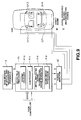
- Fig.6 is block diagram showing an arrangement of an optical disc reproducing apparatus as the recording and/or reproducing apparatus for the disc-shaped recording medium according to a first embodiment of the present invention.
- Fig.7 illustrates the list display format on the display unit of the optical disc reproducing apparatus according to the first embodiment in a mode other than the sound field control mode.
- Fig.8 illustrates the list display format on the display unit of the optical disc reproducing apparatus according to the first embodiment in the sound field control mode.
- Fig.9 is a block diagram showing an arrangement of a sound field processor.
- Figs. 10a and 10b illustrate a recording and/or reproducing apparatus for a disc-shaped recording medium according to the present invention
- Fig.10a is a perspective view showing a schematic arrangement of the recording and/or reproducing apparatus for the disc-shaped recording medium
- Fig.10b shows the disc cartridge arraying state in the magazine employed in the apparatus shown in Fig.10a.
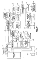
- Fig.11 is block diagram showing an arrangement of an optical disc reproducing apparatus as the recording and/or reproducing apparatus for the disc-shaped recording medium according to a second embodiment of the present invention.
- Fig.12 is a front view showing an operating panel of the optical disc reproducing apparatus according to the second embodiment of the present invention.
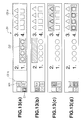
- Figs.13a to 13d illustrate the list display configuration on the display unit of the optical disc reproducing apparatus according to the second embodiment of the present invention, wherein Fig.13a shows the display format when a disc cartridge associated with the arraying number "1" of the disc cartridges in the magazine is selected, Fig.13b shows the display format when a disc cartridge associated with the arraying number "2" of the disc cartridges in the magazine is selected, Fig.13c shows the display format when a disc cartridge associated with the arraying number "3" of the disc cartridges in the magazine is selected and Fig.13d shows the display format when a disc cartridge associated with the arraying number "4" of the disc cartridges in the magazine is selected.
- Fig.14 is a block diagram showing an arrangement of a sound field processor.
- Fig.15 is a perspective view showing the appearance and the mounting state of a rotary switch employed in the apparatus according to the second embodiment of the present invention.
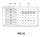
- Fig.16 illustrates another list display configuration on the display unit of the apparatus of the present invention.
- a disc recording and/or reproducing apparatus for a disc-shaped recording medium according to a first embodiment of the present invention is explained.
- the schematic arrangement of a car-laden audio equipment, to which is applied the recording and/or reproducing apparatus for the disc-shaped recording medium according to the present invention is explained.
- the car-laden audio equipment to which is applied the recording and/or reproducing apparatus for the disc-shaped recording medium according to the present invention, includes a magazine for containing plural disc cartridges, each containing an optical disc, such as a replay-only optical disc or a write type magneto-optical disc, rotatably therein. Within the magazine, plural disc cartridges are contained in the horizontal position.
- an optical disc such as a replay-only optical disc or a write type magneto-optical disc
- the car-laden audio apparatus includes an optical disc reproducing unit for selectively reproducing information signals from the optical disc of one of the disc cartridges and outputting the reproduced audio information signals via four speakers, and a sound field processor for creating an acoustic field in a narrow car space by controlling the reverberating sound and for improving the fixed sound image by the output sound volume balance from the four speakers and adjustment of the phase delay of the audio output.
- the optical disc reproducing apparatus includes a main member of the reproducing apparatus 4 and an operating panel 5, as shown in Fig.5a.
- a magazine 2 in which four disc cartridges 1 at the maximum are loaded in a planar array of two rows by two columns.
- the operating panel 5 is mounted for opening/closing movement with respect to the entrance/exit opening 3 by a hinge, not shown, on the front surface of the main member of the reproducing apparatus 4.
- the optical disc contained in the disc cartridge 1 has recorded thereon table-of-contents data (TOC data) used for retrieving the title of the information signals or music signals recorded in the recording region, the title of the optical disc and so-called album title.
- TOC data table-of-contents data
- a rotary table for rotation with respect to a chassis.
- a spindle motor and an optical pickup both of which are halted at pre-set positions (home positions) as a result of initial rotation of the rotary table on power on of the main member of the reproducing apparatus 4.
- the spindle motor and the optical pickup are positioned in register with the disc cartridge 1 loaded at the second row of the first column, that is at a position indicated by the array number "1" in Fig.5b.
- the shutter mounted on this disc cartridge 1 is opened, the spindle motor and the optical pickup are positioned in register with an exposed portion of the optical disc enclosed within the disc cartridge 1.
- the optical pickup is made up of a laser light source for radiating a laser beam for reading out information signals recorded on the optical disc, an objective lens for converging the laser beam from the laser light source on the recording surface of the optical disc, and a photodetector for photo-electrically converting the light reflected by the recording surface of the optical disc into electrical detection signals.
- the objective lens is driven by an actuator, not shown, in the focusing direction and in the tracking direction based upon focusing error signals and tracking error signals.
- the optical pickup is driven radially of the optical disc loaded on the turntable by a linear motor feed mechanism.
- the reproducing circuitry of the main member of the reproducing apparatus 4 is explained by referring to Fig.6.
- the reproducing circuitry includes a cartridge detector 11 for optically detecting the disc cartridge 1 loaded on the magazine 2 introduced into the main member of the reproducing apparatus 4, a rotary table driving circuit 12 for rotationally driving the rotary table in one direction, and a rotary position detector 13 for detecting the rotary position or the angle of rotation of the rotary table.
- the rotary table driving circuit 12 first runs the rotary table in rotation, based upon reception on power-on of a start signal from a controller 57 in the display unit, as later explained, for halting the optical pickup 14 and the spindle motor 15 at the home position, that is at a position registering with the disc cartridge 1 loaded on the second row of the first column in Fig.5b.
- the detection signal from the cartridge detector 11 is supplied to the controller as later explained.
- the controller formulates the flag information, based upon the detection signal supplied thereto, and stores the flag information in a data register memory as later explained.
- the detection signal from the cartridge detector 11 is also supplied to a rotary table driving circuit 12.
- the rotary table driving circuit 12 holds the detection signal supplied thereto in order to control the driving rotation of the rotary table based upon the contents of the detection signal. That is, the rotary table driving circuit 12 runs the rotary table in rotation as it causes the spindle motor 15 and the optical pickup 14 to be skipped so that these are not positioned in register with the portions of the magazine not carrying the disc cartridge 1.
- the rotary table driving circuit 12 rotates the rotary table in one direction based upon the number data from the controller as later explained for halting the optical pickup 14 and the spindle motor 15 at the position registering with the disc cartridge 1 corresponding to the number data.
- a rotary table driving circuit 42 For controlling the rotation of the rotary table in a rotary table driving circuit 42, it is possible to read out the rotational angle data corresponding to the input number data from a rotational angle data table in a memory 16, count the number of rotational clock signals supplied in succession from the rotational position detection circuit 13 and to halt the rotational table when the count value coincides with the read-out rotational angle data.
- the reproducing circuitry also includes a spindle servo circuit 17, a focusing/tracking servo circuit 18, an error signal generating circuit 19, a demodulating circuit 20, a L-R separating circuit 21, a TOC data extracting circuit 22 and an address data extracting circuit 23.
- the spindle servo circuit 17 servo-controls the spindle motor 15 so that the optical disc is run in rotation at a constant linear velocity.
- the focusing/tracking servo circuit 18 controls the actuator of the optical pickup 14 for focusing controlling and tracking controlling the objective lens.
- the error signal generating circuit 19 generates spindle servo error signals, focusing servo error signals and tracking servo error signals based upon detection signals from the optical pickup 14.
- the demodulating circuit 20 converts the detection signals from the optical pickup 14 to digital signals and decodes code data appended for error correction in order to output the resulting signals as playback data.
- the L-R separating circuit 21 converts the playback data from the demodulating circuit 20 to analog signals and separates them into left channel signals and right channel signals which are outputted as left side audio signals and right side audio signals, respectively.
- the TOC data extracting circuit 22 extracts TOC data from the playback data from the demodulating circuit 20.
- the address data extracting circuit 23 extracts track address data from the playback data from the demodulating circuit 20.
- the TOC data from the TOC data extracting circuit 22 is stored in a TOC data file logically apportioned in a data register memory through a controller as later explained.
- the rotary table driving circuit 12 When the rotary table driving circuit 12 has rotated the rotary table in one direction and has halted the optical pickup 14 and the spindle motor 15 at a position registering with the disc cartridge 1 corresponding to the input number data, it issues a start signal to a vertical movement mechanism, not shown, designed for producing the vertical movement of the spindle motor 15.
- the vertical movement mechanism causes the spindle motor 15 to be moved upwards, for example, responsive to the start signal from the rotary table driving circuit 12, for loading the optical disc on the turntable of the spindle motor.
- the start signal from the rotary table driving circuit 12 is also supplied to the spindle servo circuit 17 and to the optical pickup 14.
- the spindle servo circuit 17 drives the spindle motor 15 responsive to the start signal from the rotary table driving circuit 12 and to the end of loading of the optical disc on the turntable.
- the optical disc loaded on the turntable is rotated with, for example, a constant linear velocity (CLV).
- the optical pickup 14 is started responsive to the start signal from the rotary table driving circuit 12 and moved radially of the optical disc, as it radiates the laser beam on the recording surface of the optical disc, for sequentially reading out the information signals recorded on the recording surface of the optical disc.
- the right side audio signals and the left side audio signals, outputted from the L-R separating circuit 21, are supplied to a sound field processor 41 as later explained.
- the operating panel 5 has a display surface 31 at a mid part on its front surface and a transverse array of ten-keys 32 at a lower portion with respect to the display surface 31, as shown in Fig.7.
- a selector button 33 for starting the sound field processor is arranged on the left-hand side of the ten-keys 32.
- the sound field processor 41 is arranged between the main member of the reproducing apparatus 4 and a four-fold power amplifier 42 connected to four speakers SP1 to SP4 arranged at the four corners in the car compartment, as shown in Fig.9.
- the sound field processor 41 includes an initial reflected sound/reverberating sound generator 41a, a graphic equalizer 41b, a compressor 41c and a sound image processor 41d.
- the initial reflected sound/reverberating sound generator 41a generates the initial reflected sound and the reverberating sound based on the data of the sound field, such as a music hall.
- the graphic equalizer 41b corrects the frequency response and transmission characteristics of the speakers.
- the compressor 41c is used for improving the S/N ratio by reducing the dynamic range.
- the sound image processor 41d is used for improving the fixed position sense of the sound image by adjusting the phase delay of the audio output and the sound volume balance of the audio sound outputted from the 4-channel speakers SP1 to SP4 in connection with seat positions associated with the seat numbers as selected by the operating panel 5.
- the display device is made up of a display unit 51, inclusive of a display screen 31 arranged on the operating panel 5, and a display processing circuitry 52 for generating display data for making a screen display by means of the display unit 51, as shown in Fig.6.
- the display unit 51 includes a liquid crystal display, for example, which has its display screen 31 divided into two display regions 31a and 31b.
- the display region 31a is a character display region for displaying letters, figures and so forth.
- the other display region 31b is a graphic display region for displaying a symbol mark simulating the outer shape of the disc cartridge 1, termed a cartridge symbol SM1, as shown in Fig.7, a symbol mark simulating the dashboard within the car compartment, termed a dashboard symbol SM2 and a symbol mark simulating the shelf at back of the rear seat, termed a rear shelf symbol, as shown in Fig.8.
- the display region 31b is arranged on the left side part of the display screen 31 of the display unit 51, that is a portion above the key "1" of the ten-keys 32.
- the background of the display screen is set to a white color hue.
- cartridge symbols SM1 are displayed in correspondence with the number of the disc cartridges 1 loaded in the magazine 2 inserted into the optical disc reproducing apparatus. These four cartridge symbols SM1 are arranged in two rows by two columns in correspondence with the array of the disc cartridges 1 loaded in the magazine 2. That is, the cartridge symbols SM1 are of the symbol configuration corresponding to the arraying format of the disc cartridges 1 loaded in the magazine 2.
- the cartridge symbol SM1 When the sound field control mode is not set, that is when the selection button 33 on the operating panel 5 is not actuated, the cartridge symbol SM1 has a symbol configuration consisting of the outer profile a , a simulated shutter of the disc cartridge b and a circle c , as shown in Fig.7.
- the array number (see Fig.5b) of the disc cartridge 1 loaded in the magazine 2 is displayed within the circle c .
- the cartridge symbol SM1 for the sections of the magazine 2 not loaded with the disc cartridge 1 has only the outer profile a .
- the cartridge symbol SM1 for the array number "2" shown in Fig.5b has such configuration.
- a dashboard symbol SM2 is displayed on top of the group of the cartridge symbols SM1 arrayed in two rows by two columns, while a rear shelf symbol SM3 is displayed below the group of the cartridge symbols SM1, as shown in Fig.8.
- the arraying numbers are entered in all of the circles of the cartridge symbols SM1.
- part of the cartridge symbol SM1 associated with the optical disc being displayed is displayed in color. That is, the area in the outer profile a exclusive of the inside of the circle c and the inside of the shutter symbol b , indicated by hatching, is displayed in a blue color hue.
- the display processing circuitry 52 of the display device includes a character data processor 53, a ROM 54, a graphic data processor 55, a display processor 56 and the controller 57, as shown in Fig.6.
- the character data processor 53 generates character data for the arraying number of the disc cartridge being reproduced, the optical disc title and the track being reproduced, and the playback time.
- the graphic data processor 55 reads out fixed data concerning the cartridge symbol SM1 registered in the ROM 54, herein data concerning the outer profile a , and generates outer profile arraying data from the read-out fixed data.
- the outer profile arraying data is used for displaying the cartridge symbols in a pre-set arraying configuration, that is in a configuration of two rows by two columns.
- the data processor 55 selectively combines data concerning the shutter symbol b , arraying number data or color display data with the outer profile data for generating the graphic data to be displayed in the display region 31b.
- the display processor 56 synthesizes the graphic data from the graphic data processor 55 and character data from the character data processor 53 in order to display the synthesized data in the display region 31b of the display unit 51.
- the controller 57 controls the above-mentioned circuits based upon the operation of the various keys provided on the operating panel 5.
- a start signal is supplied from the controller 57 to the rotary table driving circuit 12.
- the rotary table driving circuit 12 is responsive to the start signal from the controller 57 for rotationally driving the rotary table and halts the optical pickup 14 and the spindle motor 15 at the home position, that is at a position registering with the optical disc of the disc cartridge loaded at the second row of the first column, indicated by the array number "1" in Fig.5b.
- the disc cartridges 1 are then inserted into the sections of the magazine 2 bearing the arraying numbers 1, 3 and 4, without loading the disc cartridge for the arraying number 2.
- the magazine 2 thus containing three disc cartridges 1 are then introduced via the entrance/exit opening 3 into the main member of the reproducing apparatus 4.
- the cartridge detector 11 then optically detects the disc cartridge loading state in the magazine 2.
- a detection signal from the detector 11 is supplied to the controller 57 and to the rotary table driving circuit 12.
- the controller 57 stores the detection signal from the cartridge detector 11 as the flag information in a data register memory 58.
- the rotary table driving circuit 12 holds the detection signal from the cartridge detector 11 as the rotation-skipping information.
- the controller 57 then reads out the flag information from the data register memory 58 and routes the read-out information to the graphic data processor 55.
- the graphic data processor 55 formulates graphic data based upon the flag information from the controller 57.
- the graphic data in this case comprises the outer profile a of the cartridge symbol having the array number "2" and the combination of the outer profile a , the shutter-simulating symbol b and the circle c for each of the cartridge symbols SM1 having the array numbers "1", "3" and "4".
- the graphic data is displayed in the display region 31b of the display unit 51 by means of the display processor 56.
- the TOC data of the optical disc having the array number "1" is read, responsive to the start signal from the rotary table driving circuit 12.
- the TOC data thus read out is stored in the address region in the data file of the data register memory 58 associated with the array number "1" under control by the controller 57.
- the rotary table driving circuit 12 then causes the rotary table to be rotated in order to shift the spindle motor 15 and the optical pickup 14 to a position registering with the disc cartridge 1 having the array number "3" and to read out the TOC data of the optical disc associated with the array number "3".
- the TOC data thus read out is stored in the address region associated with the array number "3” in the TOC data file of the data register memory 58 associated with the array number "3", under control by the controller based upon the flag information.
- the array number "2" is skipped by the rotary table driving circuit 12 as the corresponding disc cartridge 1 is not loaded.
- the rotary table driving circuit 12 then causes the rotary table to be rotated in order to shift the spindle motor 15 and the optical pickup 14 to a position registering with the disc cartridge 1 having the array number "4" and to read out the TOC data of the optical disc associated with the array number "4".
- the TOC data thus read out is stored in the address region associated with the array number "4" in the TOC data file of the data register memory 58 associated with the array number "4".
- the user then actuates the key of the ten-key 32 having the number "4" in order to reproduce the optical disc having the array number "4".
- the key input data is supplied to the controller 57 which then outputs the key input to the rotary table driving circuit 12.
- the rotary table driving circuit 12 then is responsive to the key input data to cause the rotation of the rotary table in order to shift the spindle motor 15 and the optical pickup 14 to a position registering with the disc cartridge 1 having the array number indicated by the key input data, herein the array number "4".
- the optical pickup 4 causes the information signals to be reproduced from the optical disc of the disc cartridge 1 having the array number "4".
- the key input data from the controller 57 is also supplied to the character data processor 53 and the graphic data processor 55 in the display processing circuitry 52 of the display unit.
- the character data processor 53 is responsive to the key input data supplied thereto to read out the title data of the optical disc and the play time data from the TOC data for the array number "4" of the data register memory 58.
- the data processor 53 also routes the title data, the play time data and the track address data supplied from the address data extraction circuit 23 of the optical disc reproducing device.
- the graphic data processor 55 is responsive to the supplied key input data to append additional data for making color display of the cartridge symbol SM1 having the array number "4" to the generated graphic data.
- the resulting combined data is supplied to the display processor 56.
- the display processor 56 synthesizes character data supplied from the character data processor 53 and the graphic data processor 55 in order to display the character data in the display region 31a and the graphic data in the display region 31b.
- the disc title, array number, track number and the play time are displayed in the display region 31a.
- the outer profile a of the cartridge symbol SM having the array number "2" and the combination of the outer profile a , the shutter simulating symbol b and the circle c for each of the cartridge symbols SM1 having the array numbers "1", "3" and "4" are displayed in the display region 31b. Only the cartridge symbol SM1 having the array number "4" is displayed in color.
- the disc title and the array number are modified by the array number entry operation by the ten-key 32.
- the track number is updated as the updated track address is caused to enter the character data processor 53 via the address data extracting section 23 as the optical disc reproduction in the main member of the reproducing apparatus 4 proceeds.
- the play time is updated by the second-based countup (count update) of clock signals sequentially inputted from a timer 59 to the character processor 53.
- the color display of the cartridge symbol SM1 for the optical disc being reproduced is modified by the inputting operation of the array number by the ten-key 32.
- the audio apparatus shifts to the sound field control mode.
- the on-signal generated on actuation of the select button 33 is supplied to the controller 57.
- the controller 57 is responsive to the supply of the on-signal to retrieve the status flag information within the data register memory 58. If, as a result of the retrieval, there is found no bit set for indicating that the mode is the sound field control mode, the bit is set and a sound field control command signal is outputted to the sound field processor 41 and the graphic data processor 55 in the display unit.
- the sound field processor 41 permits data entry based upon the inputting of the sound control command signal from the controller 57.
- dashboard symbol SM2 is displayed on top of the cartridge symbols SM1 arranged in two rows by two columns in the display region 31b, while the rear shelf symbol SM3 is displayed below the cartridge symbols SM1 and array symbols are displayed in the associated cartridge symbols SM1 and SM2.
- the cartridge symbol SM1 displayed in the display region 31b has a shape similar to the seat array in the car compartment. If the sound image is desired to be tuned to the driver's seat, the array number "3" of the cartridge symbol SM1 at the array position of the driver's seat is entered using the ten-key 32.
- the key input data by the ten-key 32 is routed to a sound image processing section 41d of the sound processor 41 which is in the key-input state.
- the sound image processing section 41d has a memory therein in which a table correlating the array number with the actual seat position is registered as a data table.
- the sound image processing section 41d collates the array number indicated by the input data entered by the ten-key 32 with the array number in the data table for indexing the actual seat position and executes processing for improving the fixed position sense of the sound image in connection with the thus indexed seat position.
- the controller 57 retrieves the bit state of the flag information in the data register memory 58 indicating that the mode is the sound field control mode. Since the bit indicating that the mode is the sound field control mode is set at this time by the first actuation of the select button 33, the controller 57 outputs a sound field control mode release signal to the sound field processor 41 and the graphic data processor 55 in the display unit by inverting this bit. The sound field processor 41 inhibits data entry based upon the sound field mode release signal from the controller 57.
- the graphic data processor 55 in the display unit is responsive to the sound field mode release signal from the controller 57 to erases data of the dashboard symbol SM2 and the rear shelf symbol SM3 from the currently displayed graphic data.
- the data processor 55 formulates the graphic data from which the currently displayed array number of the cartridge symbol SM1 not loaded in the magazine 2 has been erased and transmits the formulated graphic data to the display processor 56.
- dashboard symbols SM2 on the top and bottom of the cartridge symbols SM1 displayed in the display region 31b during the sound field control mode are erased, while the array number associated with the disc cartridge 1 not loaded in the magazine 2 is also erased.
- attributes of the disc cartridge 1 for the optical disc being reproduced are displayed as characters in the display region 31a.
- the array configuration of the four disc cartridges 1 as loaded in the magazine 2 are displayed in the display region 31b by four cartridge symbols SM1 arrayed in two rows by two columns.
- the loading state of the disc cartridges 1 in the magazine 2 introduced into the main member of the reproducing apparatus 4 is displayed by selective diagrammatic display of the respective cartridge symbols SM1.
- the user may intuitively grasp how many disc cartridges 1 are contained and in which positions of the two rows by two columns the disc cartridges are loaded.
- the graphic display for the disc cartridge for the optical disc being reproduced (cartridge symbol SM1) is displayed in a color different from that for the remaining disc cartridges (cartridge symbols SM1).
- the display configuration of the four cartridge symbols SM1 is somewhat similar to the seat array in the car compartment.
- the user when selecting the seat position under consideration with a view to improving the fixed sound image sense in the sound field control mode, it is possible for the user to identify the seat position under consideration intuitively on simply viewing the cartridge symbols SM1 arrayed in two rows by two columns. Consequently, the sound field processor may be significantly improved in operability.
- the recording and/or reproducing apparatus for a disc-shaped recording medium according to a second embodiment of the present invention is now explained. Similarly to the first embodiment, the present second embodiment is directed to a car-laden sound reproducing apparatus.
- the sound reproducing apparatus of the present embodiment also has a sound field processor.
- the optical disc used in the second embodiment also has data for retrieving information signals recorded in the recording region, such as titles of the music signals or so-calle-d album title, referred to hereinafter as table-of-contents data (TOC data).
- TOC data table-of-contents data
- the optical disc reproducing apparatus includes a main member of the reproducing apparatus 140 and an operating panel 150, as shown in Fig.10a.
- a magazine 102 in which four disc cartridges 101 at the maximum may be loaded in a planar array of two rows by two columns.
- the operating panel 5 is mounted for opening/closing movement with respect to an entrance/exit opening 103 by a hinge, not shown, on the front surface of the main member of the reproducing apparatus 140.
- a rotary table for rotation with respect to a chassis, not shown.
- a spindle motor and an optical pickup both of which are halted at a pre-set position (home position) as a result of initial rotation of the rotary table on power on of the main member of the reproducing apparatus 140.
- the spindle motor and the optical pickup are positioned in register with the disc cartridge 101 loaded at the second row of the first column, that is at a position indicated by the array number "1" in Fig.10b.
- the shutter mounted on this disc cartridge 101 is opened, the spindle motor 115 and the optical pickup 116 are positioned in register with an exposed portion of the optical disc enclosed within the disc cartridge 101.
- the optical pickup is made up of a laser light source for radiating a laser beam for reading out information signals recorded on the optical disc, an objective lens for converging the laser beam from the laser light source on the recording surface of the optical disc, and a photodetector for photo-electrically converting the light reflected by the recording surface of the optical disc into electrical detection signals.
- the objective lens is driven by an actuator, not shown, in the focusing direction and in the tracking direction based upon focusing error signals and tracking error signals.
- the optical pickup 116 is driven radially of the optical disc loaded on the turntable by a linear motor feed mechanism.
- the reproducing circuitry of the main member of the reproducing apparatus 140 is explained by referring to Fig.11.
- the reproducing circuit system includes a cartridge detector 101 for optically detecting the disc cartridge 101 loaded on the magazine 102 introduced into the main member of the reproducing apparatus 140, a rotary table driving circuit 112 for rotationally driving the rotary table in one direction, and a rotary position detector 113 for detecting the rotary position or the angle of rotation of the rotary table.
- the rotary table driving circuit 112 first runs the rotary table in rotation, based upon reception on power on of a start signal from a controller in the display unit as later explained for halting the optical pickup 114 and the spindle motor 115 at the home position, that is at a position registering with the disc cartridge 101 loaded on the second row of the first column in Fig.10b.
- the detection signal from the cartridge detector 111 is supplied to a controller as later explained.
- the controller formulates the flag information, based upon the detection signal supplied thereto, and stores the flag information in a data register memory 158 as later explained.
- the detection signal from the cartridge detector 111 is also supplied to a rotary table driving circuit 112.
- the rotary table driving circuit 112 holds the detection signal supplied thereto in order to control the driving rotation of the rotary table based upon the contents of the detection signal. That is, the rotary table driving circuit 112 runs the rotary table in rotation as it causes the spindle motor 115 and the optical pickup 114 to make a skipping movement so that these are not positioned in register with the portions of the magazine not carrying the disc cartridge 101.
- the rotary table driving circuit 112 rotates the rotary table in one direction based upon the number data from the controller as later explained for halting the optical pickup 114 and the spindle motor 115 at the position registering with the disc cartridge 101 corresponding the number data.
- the reproducing circuitry also includes a spindle servo circuit 117, a focusing/tracking servo circuit 118, an error signal generating circuit 119, a demodulating circuit 120, a L-R separating circuit 121, a TOC data extracting circuit 122 and an address data extracting circuit 123.
- the spindle servo circuit 117 servo-controls the spindle motor 115 so that the optical disc is run in rotation at a constant linear velocity.
- the focusing/tracking servo circuit 118 controls the actuator of the optical pickup 14 for focusing controlling and tracking controlling the objective lens.
- the error signal generating circuit 119 generates spindle servo error signals, focusing servo error signals and tracking servo error signals, based upon detection signals from the optical pickup 114.
- the demodulating circuit 120 converts the detection signals from the optical pickup 14 and decodes code data appended for error correction in order to output the resulting signals as playback data.
- the L-R separating circuit 121 converts the playback data from the demodulating circuit 120 to analog signals and separates them into left channel signals and right channel signals which are outputted as left side audio signals and right side audio signals, respectively.
- the TOC extracting circuit 122 extracts TOC data from the playback data from the demodulating circuit 120.
- the address data extracting circuit 123 extracts track address data from the playback data from the demodulating circuit 120.
- the TOC data from the TOC data extracting circuit 122 is stored in a TOC data file logically apportioned in a data register memory through a controller as later explained.
- the rotary table driving circuit 112 When the rotary table driving circuit 112 has rotated the rotary table in one direction and has halted the optical pickup 114 and the spindle motor 115 at a position registering with the disc cartridge 101 corresponding to the input number data, it issues a start signal to a vertical movement mechanism producing the vertical movement of the spindle motor 115.
- the vertical movement mechanism causes the spindle motor 115 to be moved upwards, for example, responsive to the start signal from the rotary table driving circuit 112, for loading the optical disc on the turntable of the spindle motor 115.
- the start signal from the rotary table driving circuit 112 is also supplied o the spindle servo circuit 117 and to the optical pickup 114.
- the spindle servo circuit 117 drives the spindle motor 115 responsive to the start signal from the rotary table driving circuit 112 and the end of loading of the optical disc on the turntable.
- the optical disc loaded on the turntable is rotated with, for example, a constant linear velocity (CLV).
- the optical pickup 114 is started responsive to the start signal from the rotary table driving circuit 112 and moved radially of the optical disc as it radiates the laser beam on the recording surface of the optical disc for sequentially reading out the information signals recorded thereon.
- the right side audio signals and the left side audio signals, outputted from the L-R separating circuit 121, are supplied to a sound field processor 141 as later explained.
- the operating panel 5 has a display surface 131 at a mid part on its front surface and a transverse array of ten-keys 132 below the display surface 131, as shown in Fig.12.
- a selector button 133 for starting the sound field processor is arranged on the left-hand side of the ten-key 132.
- a file key 134 for displaying the title of each optical discs of the disc cartridges 101 loaded in the magazine 102 is arranged on the right-hand side of the ten-key 132.
- the sound field processor 141 is arranged between the main member of the reproducing apparatus 140 and a four-fold power amplifier 142 connected to four speakers SP11, SP22, SP33 and SP44 arranged at the four corners in the car compartment, as shown in Fig. 14.
- the sound field processor 141 includes a power amplifier 142, an initial reflected sound/reverberating sound generator 141a, a graphic equalizer 141b, a compressor 141c and a sound image processor 41d and a sound image processor 141d.
- the initial reflected sound/reverberating sound generator 141a generates the initial reflected sound and the reverberating sound based upon the data of the sound field, such as a music hall.
- the graphic equalizer 141b corrects the frequency response and transmission characteristics of the speakers.
- the compressor 141c is used for improving the S/N ratio by reducing the dynamic range.
- the sound image processor 141d is used for improving the fixed position sense of the sound image by adjusting the phase delay of the audio output and the sound volume balance of the output sound from the 4-channel speakers SP11 to SP44 in connection with seat positions associated with the seat numbers as selected by the operating panel 150.
- the display unit 151 arranged on the operating panel 150 shown in Fig.11 includes a display processing circuitry designed for generating display data for making a screen display.
- the display unit 151 includes a liquid display, for example, which has its display screen 31 divided into two display regions 131a and 131b, as shown in Fig.6.
- the display region 131a is a character display region for displaying letters, figures and so forth.
- the other display region 131b is a graphic display region for displaying a symbol mark simulating the outer shape of the disc cartridge 101, termed a cartridge symbol SM, as shown in Fig.12.
- the display region 131b is arranged on the left side part of the display screen 131 of the display unit 151, that is a portion above the key "1" of the ten-key 132.
- the background of the display screen is set to a white color hue.
- cartridge symbols SM are displayed in correspondence with the number of the disc cartridges 101 loaded in the magazine 102 inserted into the optical disc reproducing apparatus. These four cartridge symbols SM are arranged in two rows by two columns in correspondence with the array of the disc cartridges 101 loaded in the magazine 102. That is, the cartridge symbols SM are of the symbol configuration corresponding to the arraying configuration of the disc cartridges 101 loaded in the magazine 102.
- the cartridge symbol SM has a symbol configuration consisting of the outer profile A , a simulated shutter of the disc cartridge B and a circle C , as shown in Fig.12.
- the array number (see Fig.10b) of the disc cartridge 101 loaded in the magazine 102 is displayed within the circle C .
- the cartridge symbol SM for the section of the magazine 2 not loaded with the disc cartridge 101 has only the outer profile A .
- the cartridge symbol SM for the array number "2" shown in Fig.5b has such configuration.
- a first cursor D1 moved responsive to the selecting operation from a rotary switch as later explained, is displayed.
- the location of the first cursor D1 may be identified by the region exclusive of the outer profile A , the circle C and the shutter-simulating symbol B of the cartridge symbol SM associated with the selected optical disc being displayed in a blue color hue, as shown by hatching in Fig.12.
- the title of the optical disc being reproduced, the array number of the disc cartridge 101 containing the optical disc, the track number being reproduced and the play time are usually displayed in characters, as shown in Fig.12.
- the array number of the disc cartridge 101 and the title of the optical disc contained in the disc cartridge 101 are displayed in characters, as shown in Figs.13a to 13d.
- the display configuration in the display region 131a in the present second embodiment is similar to that in the display region 131b, that is, the sets of the array numbers and the titles are arrayed in two rows by two columns, in a similar manner to the array configuration of the disc cartridges 101 loaded in the magazine 102.
- the display configuration in the display region 131a is such that the array number "1" of the disc cartridge 101 loaded in the second row of the first column of the magazine 102 as shown in Fig.10b are displayed, along with the title of the optical disc, in the second row of the first column of the display region 131a.
- the array number "2" of the disc cartridge 101 loaded in the first row of the first column of the magazine 102 and the title of the optical disc are displayed in the first row of the first column of the display region 131a.
- the array number "3" of the disc cartridge 101 loaded in the first row of the second column of the magazine 102 and the title of the optical disc are displayed in the first row of the second column of the display region 131a, while the array number "4" of the disc cartridge 101 loaded in the second row of the second column of the magazine 102 and the title of the optical disc are displayed in the second row of the second column of the display region 131a.
- a second cursor D2 moved on the display region 131a responsive to the selecting operation from a rotary switch as later explained, is displayed.
- the second cursor D2 has the same color as that of the first cursor D1 moved and displayed on the first display region 131b.
- the title of the optical disc at which the second cursor D2 is located has the background displayed with the same color as that of the second cursor and has title letters displayed in white by so-called luminance inversion display.
- a rotary switch 171 for selecting the disc cartridges 101 in the magazine 102 has a rotary knob 175 rotatably mounted at the distal end thereof.
- a rotary knob 175 By rotating the rotary knob 175 in the direction shown by an arrow in Fig.15, plural switches, not shown, provided in the rotary switch 171, may be turned on and off for switching.
- the results of the switching operations by the rotary knob 175 are routed via a cord connected to the rotary switch 175 to a controller as later explained.
- the rotary switch 171 is mounted substantially horizontally on a steering column 174 at back of a wiper lever 173 in the vicinity of a steering handle 172 of a car in order for the driver to actuate the switch 171 easily, as shown in Fig.15. If,for example, the rotary knob 175 is rotated clockwise, a signal (+) is outputted from the rotary switch 171, whereas, if the rotary knob 175 is rotated counterclockwise, a signal (-) is outputted from the rotary switch 171.
- the controller is operated responsive to clockwise operation of the rotary switch 175 to control the main member of the apparatus 140 in order to select the disc cartridge 101 in the magazine 102 so that the array number of the disc cartridge 101 is incremented by one for each knob actuation. After the array number "4", the array number reverts to "1". Conversely, if supplied with the (-) signal, the controller selects the disc cartridges 101 in the magazine 102 so that the array number of the disc cartridge 101 is decremented by one for each knob actuation. After the array number "1", the array number reverts to "4". The details of the control operation will be explained subsequently.
- the display processing circuitry 152 in the display unit 151 includes a character data processor 153, a ROM 154, a graphic data processor 155, a display processor 156 and a controller 157, as shown in Fig.11.
- the character processor 153 generates character data to be displayed in the display region 131a.
- the graphic data processor 155 generates graphic data to be displayed in the display region 131b.
- the display processor 156 synthesizes the graphic data from the graphic data processor 155 and the character data from the character data processor 153 and displays the graphic data and the character data in the display region 131a and in the display region 131b of the display screen 131, respectively.
- the controller 157 is responsive to actuation of the various keys on the operating panel 150 to supply control signals to the above-mentioned various circuits and to the main member of the apparatus 140.
- the character data processor 153 Unless the file key 134 is actuated, the character data processor 153 generates the array number of the disc cartridge 101 being reproduced, the title of the optical disc, the number of the track being reproduced, and the play time. If the file key 134 is actuated, the data processor 153 generates the display data for displaying the array number of the disc cartridge 101 loaded in the magazine 102 and the title of the optical disc in a list of two rows by two columns. The data processor 153 also generates character data comprised of color data concerning the second cursor display and data for luminance inversion display which becomes necessary in connection with the second cursor display.
- the graphic data processor 155 reads out fixed data concerning the cartridge symbol SM registered in the ROM 154, herein data concerning the outer profile A , and generates from the read-out fixed data the outer profile array data for displaying the outer profile data in a pre-set array configuration of two rows by two columns.
- the graphic data processor 155 generates graphic data comprised of data concerning the shutter-simulating profile and the array number data as well as the color display data for the first cursor selectively combined into the outer profile array data.
- the operation of the audio apparatus will be explained in conjunction with the operation of the optical disc reproducing apparatus and the sound field processor.
- a start signal is routed from the controller 157 to the rotary table driving circuit 112.
- the rotary table driving circuit 112 runs the rotary table in rotation, responsive to the start signal from the controller 157, until the optical pickup 114 and the spindle motor 115 are stopped at the home position, that is at a position registering with the optical disc loaded in the second row of the first column, indicated by the array number "1" in Fig.10b.
- the magazine 102 containing the disc cartridges 101 at the sections thereof having the array numbers "1", “3” and “4" without containing the disc cartridge 101 at the section thereof having the array number "2"
- the loading state of the disc cartridges 101 loaded in the magazine 102 is optically detected by the cartridge detector 111.
- a detection signal from the detector 111 is routed to the controller 157 and the rotary table driving circuit 112.
- the detection signal from the cartridge detector 111 is stored as the flag information in the data register memory 158.
- the rotary table driving circuit 112 holds the detection signal from the cartridge detector 111 as the information for rotation skipping.
- the controller 157 then reads out the flag information from the data register memory 158 and routes the information to the graphic data processor 155.
- the graphic data processor 155 generates the graphic data based upon the flag information from the controller 157.
- the graphic data in this case comprises the display only of the outer profile A for the cartridge symbol SM associated with the array number "2" and the combination of the outer profiles A , the shutter-simulation profiles B and the circles C for the cartridge symbols "1", "3" and "4".
- These graphic data are displayed via the display processor 156 in the display region 131b of the display screen 131.
- the TOC data of the optical disc associated with the array number "1" is then read out based upon the start signal from the rotary table driving circuit 112.
- the TOC data thus read out are stored in the address region in the TOC file associated with the array number "1".
- the rotary table driving circuit 112 runs the rotary table in rotation in order to shift the spindle motor 115 and the optical pickup 114 to a position registering with the disc cartridge 101 having the array number "3" in order to read out the TOC data of the optical 1 disc having the array number "3".
- the TOC data thus read out is stored in the address region of the TOC data file of the data register memory 158 associated with the array number "3", under control by the controller 157, based upon the flag information.
- the disc cartridge 101 is not loaded in the location of the magazine 102 having the array number "2", so that the array number "2" is skipped by the rotary table driving circuit 112.
- the rotary table driving circuit 112 again runs the rotary table in rotation for shifting the optical pickup 114 and the spindle motor 115 to the address region in the TOC data file of the data register memory 158 having the array number "4" in order to read out the TOC data of the optical disc associated with the array number "4" in the same manner as described above.
- the read-out TOC data is then stored in the address region in the data file of the data register memory 158 associated with the array number "4" under control by the controller 157 based upon the flag information.
- the key number "1" in the ten-key 132 is actuated for reproducing the optical disc associated with the array number "1".
- the key input data is supplied to the controller 157.
- the controller 157 outputs the key input data to the rotary table driving circuit 112.
- the rotary table driving circuit 112 is responsive to the key input data to run the rotary table in rotation for shifting the optical pickup 114 and the spindle motor 115 to the position associated with the disc cartridge 101 having the array number indicated by the key input data, herein the array number "1". As a result, the information signals are read from the optical disc by the optical pickup 114.
- the key input data from the controller 157 is also supplied to the character data processor 153 and the graphic data processor 155 of the display processing circuitry 152 of the display unit.
- the character processor 153 is responsive to the key input data to read out the title data and the play time data of the optical disc from the TOC data of the data register memory 158 concerning the array number "1".
- the title data and the play time data thus read out and the track address data supplied from the address data extraction circuit 123 are supplied to the display processor 156.
- the graphic data processor 155 is responsive to the key input data to append the additional data necessary for displaying the first cursor D1 to the cartridge symbol SM having the array number "1" in the generated graphic data in color and routes the resulting combined data to the display processor 156.
- the display processor 156 synthesizes the character data and the graphic data supplied from the character data processor 153 and the graphic data processor 155, respectively.
- the display processor 156 causes the character data and the graphic data in the display regions 131a and 131b, respectively.
- the disc title, array number, track number and the play time are displayed in the display region 131a.
- the display region 131b only the outer profile for the cartridge symbol SM associated with the array number "2" is displayed, while the combination of the outer profiles A , the shutter-simulation profiles B and the circles C for the cartridge symbols "1", "3" and "4" is displayed.
- the first cursor D1 is displayed within the cartridge symbol SM associated with the array number "1".
- the optical disc title and the array number are modified by the entry operation of the corresponding array number by the ten-key 132.
- the track number is updated by the track address reproduced with the reproduction of the optical disc by the main member of the reproducing apparatus 140 and entering the character data processor 153 via the address data extraction circuit 123.
- the play time is updated by the second-based count updating of the clock signals sequentially entering the character data processor 153 from a timer 159.
- the display of the first cursor in the cartridge symbol SM being reproduced is modified by the array number entering operation by the ten-key 132 or by the selective operation by the rotary switch 171.
- the selection button 133 on the operating panel 150 is then actuated whilst the optical disc associated with the array number "1" is displayed. This causes the audio apparatus to proceed to the sound field control mode.
- the on-signal produced by actuating the selection button 133 is routed to the controller 157.
- the controller 157 is responsive to this on-signal to retrieve the status flag information in the data register memory 158. If the result of retrieval indicates that a bit showing that the current mode is the sound field control mode is not set, the bit is set, and a sound field control command signal is outputted to the sound field processor 141 and the graphic data processor 155 in the display unit.
- the sound field processor 141 permits data entrance responsive to the entry of the sound field control command signal from the controller 157.
- the cartridge symbols SM displayed in the display region 131b are similar in profile to the seat array in the car compartment. If it is desired to set the sound image in the driver's seat, it suffices to enter the array number of the cartridge symbol SM at the array position corresponding to the driver's seat using the ten-key 132.
- the key input data by the ten-key 132 is routed to the sound image processor 141d of the sound processor 141 which is in the key input state.
- the sound image processor 141d has built therein a memory in which a table associating the array numbers with the actual seat positions is registered as a data table.
- the sound field processor 141d collates the array numbers indicated by the key input data as inputted by the ten-key 132 with the array numbers of the data table for indexing the actual seat positions and performs the operation of improving the fixed sound image sense with respect to the thus indexed seat position.
- the on-signal resulting from the actuation of the selection button 133 is again routed to the controller 157 which then retrieves the bit state of the flag information indicating that the mode is the sound field control mode. At this time, the bit indicating that the mode is the sound field control mode is set. Consequently, the controller 157 inverses the bit in order to output a sound field control release signal to the sound processor 141 and the graphic data processor 155 in the display unit. The sound field processor 141 inhibits data entry based upon the entrance of the sound field control release signal from the controller 157.
- the on-signal produced on actuation of the file key 134 is routed to the controller 57 which is then responsive thereto to retrieve the status flag information in the data register memory 158. If, as a result of retrieval, there is no bit set indicating that the list display is being made, the bit is set and a display demand signal is outputted to the character data processor 153. At this time, the array number data concerning the optical disc being displayed is outputted simultaneously.
- the character data processor 153 is responsive to the entry of the list display demand signal from the controller 157 to read out title data of each optical disc from the TOC data file in the data register memory 158. At this time, reference is made to the flag information indicating the loading state of the disc cartridges 101 and, as for the sections of the magazine not loaded with the disc cartridge, the corresponding title data is read out as the space data.
- the data processor 153 formulates list data for list display of the array numbers of the disc cartridges 101 contained in the magazine 102 and the titles of the optical discs in two rows and two columns. Besides, color data for display of the second cursor and data for luminance inversion display necessary for the second cursor display are selectively appended to the list data to produce character data which is actually displayed in the display region 131a. Since the array number of the optical disc being reproduced is "1", character data is produced which is comprised of the array number "1", coordinate data commanding the title display position and the second cursor displaying data appended to the list data.
- the character data produced by the character data processor 153 is displayed via the display processor 156 in the display region 131a of the display screen 131, as shown in Fig.11.
- the display configuration at this time is such that the second cursor D2 is located in the title display portion registering with the second row of the first column of the list display, with the title being displayed with luminosity inversion, as shown in Fig.13a.
- the controller 157 increments the array number data concerning the optical disc being reproduced by one (+1). If the array number for the optical disc being reproduced is "4", the array number data is set to "1". The cursor update signal and the updated array number data are supplied to the character data processor 153 and to the graphic data processor 155.
- the character data processor 153 is responsive to the cursor update signal and the array number data from the controller 157 to produce character data which is comprised of the list data already displayed and the coordinate data appended thereto for indicating the position of the title of the number as indicated by the array number data and the second cursor display data.
- the graphic data processor 155 formulates graphic data which is comprised of displayed data of the cartridge symbol in two rows by two columns, coordinate data indicating the position of the cartridge symbol SM as indicated by the array number data and the first cursor display data.
- the character data produced by the character data processor 153 and the graphic data produced by the graphic data processor 155 are displayed via the display processor 156 in the display regions 131a and 131b of the display screen 131, respectively.
- the second cursor D2 displayed in the display region 131a is displayed at the position of the cartridge symbol SM registering with the array number "2" at the first row of the first column, and the title is displayed with luminance inversion, as shown in Fig.13b.
- the first cursor D1 displayed in the display region 131b is displayed at the position of the cartridge symbol SM registering with the array number "2" at the first row of the first column, and the title is displayed with luminance inversion.
- the second cursor D2 displayed in the display region 131a is displayed at the title position registering with the array number "3" at the first row of the second column, while the disc title is displayed with luminance inversion, as shown in Fig.13c.
- the first cursor D1 displayed in the display region 131b is displayed at the position of the cartridge symbol SM registering with the array number "3" at the first row of the second column.
- the second cursor D2 displayed in the display region 131a is displayed at the title position registering with the array number "4" at the second row of the second column, while the disc title is displayed with luminance inversion, as shown in Fig.13d.
- the first cursor D1 displayed in the display region 131b is displayed at the position of the cartridge symbol SM registering with the array number "4" at the second row of the second column.
- an interrupt signal due to timeout is fed from the timer 159 to the controller 157.
- the controller 157 is responsive to the entry of the interrupt signal from the timer 159 to output the updated array number data to the rotary table driving circuit 112.
- the rotary table driving circuit 112 is responsive to the input array number data to run the rotary table in rotation for shifting the optical pickup 114 and the spindle motor 115 to a position registering with the number indicated by the array number data, herein the array number "4", for reproducing the associated optical disc.
- the operating knob 175 of the rotary switch 171 is rotated counterclockwise, the (-) signal is produced form the rotary switch 171 and fed to the controller 157 which then decrements the array number data for the optical disc being reproduced by (-1). Above all, if the array number of the optical disc being reproduced is "1", the array number data is set to "4".
- the cursor update signal and the updated array number data are routed to the character data processor 153 and to the graphic data processor 155.
- the character data processor 153 is responsive to the cursor update signal and the array number data from the controller 157 to formulate character data comprised of the list data which is already displayed and which is now combined with coordinate data indicating the title of the number indicated by the array number data and character data for the second cursor.
- the graphic data processor 155 generates graphic data comprised of data of the cartridge symbol at the second row of the second column which is already displayed and which is combined with coordinate data indicating the position of the cartridge symbol SM associated with the number indicated by the array number data and the first cursor displaying data.
- the second cursor D2 displayed in the display region 131a is displayed at the title position registering with the array number "2" at the first row of the first column, while the disc title is displayed with luminance inversion, as shown in Fig.13b.
- the first cursor D1 displayed in the display region 131b is displayed at the position of the cartridge symbol SM registering with the array number "2" at the first row of the first column.
- the second cursor D2 displayed in the display region 131a is displayed at the title position registering with the array number "1" at the second row of the first column, while the disc title is displayed with luminance inversion, as shown in Fig.13a.
- the first cursor D1 displayed in the display region 131b is displayed at the position of the cartridge symbol SM registering with the array number "1" at the second row of the first column.
- the display unit 131 thereof, the array numbers of plural disc cartridges 101 loaded. in the magazine 102 and the titles of the optical discs are displayed as a list.
- the planar array state of the disc cartridges 101 loaded in the magazine 102 in two rows by two columns and the loading state of the disc cartridges 101 in the magazine 102 are graphically displayed as the cartridge symbols SM.
- the list display configuration in the display region 131a is similar to the array configuration of the disc cartridges 101 as displayed in the graphic display region 131a and to the loading state of the disc cartridges in the magazine 102, so that it becomes possible for the user to grasp intuitively how many disc cartridges 101 are loaded and in which of the two rows by two columns thee disc cartridges are loaded by consulting the graphic display of the disc cartridges SM displayed in the display region 131b.
- the first cursor D1 is displayed in color and in register with the cartridge symbol SM for the optical disc from which the information signals are being reproduced. Consequently, the optical disc being reproduced can be identified instantaneously.
- the second cursor D2 is displayed in register with the title display of the optical disc from which information signals are being displayed. Furthermore, the title of the portion of the display unit where the second cursor D2 is displayed is displayed with luminance inversion, so that the optical disc being reproduced can be identified instantaneously.
- the rotary switch 171 when the rotary switch 171 is rotated for selecting the disc cartridges 101 one by one from the array in two rows by two columns of the disc cartridges 101, the second cursor D2 and the first cursor D1 are moved on the display regions 131a and 131b, respectively, depending on the direction of rotation of the operating knob, for selective actuation of the rotary switch 171. In this manner, it can be grasped instantaneously which optical discs having certain and certain attributes have been selected, while the exchange operation of the disc cartridges 101 into the magazine 101 is facilitated.
- optical disc reproducing apparatus it is possible for four disc cartridges 101 to be loaded in the magazine in a planar array of two rows by toe columns.
- the above-described embodiments may also be applied to an optical disc reproducing apparatus in which six discs, for example, may be stacked in a magazine with the plate surfaces lying horizontally and with vertical gaps between the adjoining discs in the vertical direction.
- the display surface solely is shown in Fig.16 wherein the display regions 131b and 131a of the display screen are allocated at the left-hand and right-hand sides, respectively.
- Six of the symbol marks SM for the optical discs displayed in the display region 131b are arrayed horizontally.
- the array numbers are displayed in the symbol marks SM.
- the list display in the display region 131a comprises the array numbers and the disc titles in characters in association with the six symbol marks displayed in the display region 131b.
- sequence of the numerical figures of the array numbers in the symbol marks in the display region 131b and the sequence of the array numbers in the display region 131a are "1", "2", ⁇ , "6" as seen from the bottom side towards the upper side in correspondence with the array sequence of the optical discs arranged in the magazine 102.
- the color display of the symbol marks SM in the display region 131b is made with variable colors for the respective genres or categories of the music recorded in the optical disc, such as jazz, fusion, rock or songs.
- the cursor D indicating the optical disc being reproduced is displayed at the title position registering with the optical disc being reproduced as a list, while the title is displayed by luminance inversion.
- the present invention may also be applied to the optical disc recording apparatus.
Claims (14)
- Appareil d'enregistrement et/ou de reproduction (4) pour un support d'enregistrement en forme de disque (1), ledit support d'enregistrement (1) comportant une région d'enregistrement d'informations pour enregistrer des signaux d'informations et une région de table de contenu dans laquelle sont enregistrées au moins les données de numéro et les données de titre des signaux d'informations enregistrés dans ladite région d'enregistrement d'informations, comprenantcaractérisé en ce que lesdits supports d'enregistrement en forme de disques (1) sont agencés de manière coplanaire dans une relation côte à côte etune unité d'enregistrement et/ou de reproduction dans laquelle sont chargés une pluralité desdits supports d'enregistrement en forme de disques (1), ladite unité d'enregistrement et/ou de reproduction enregistrant les signaux d'informations sur un support sélectionné parmi lesdits supports d'enregistrement en forme de disques (1) et/ou reproduisant les signaux d'informations provenant du support d'enregistrement en forme de disque (1) sélectionné, etune unité d'affichage (51, 151) dont l'opération d'affichage est commandée par un signal de sortie provenant de ladite unité d'enregistrement et/ou de reproduction,ladite unité d'affichage (51, 151) comprend une première région d'affichage (31a, 131a) pour afficher les données enregistrées dans ladite région de table de contenu (31b, 131b) et une seconde région d'affichage présentant la même configuration d'affichage que ladite pluralité de supports d'enregistrement en forme de disques.
- Appareil de reproduction audio comprenant :l'appareil d'enregistrement/reproduction selon la revendication 1,une pluralité de haut-parleurs (SP1, SP2, SP3, SP4) recevant un signal de sortie de ladite unité d'enregistrement et/ou de reproduction et sortant ledit signal de sortie après sa conversion en une sortie audio, etun contrôleur de champ sonore (41, 141) pour faire correspondre la position fixée d'un son-image correspondant à une sortie audio desdits haut-parleurs à une position d'écoute de son audio sélectionnée,dans lequel la position d'écoute de son audio commandée par ledit contrôleur de champ sonore est affichée sur ladite unité d'affichage (51) en utilisant ladite seconde région d'affichage (31b).
- Appareil de reproduction audio selon la revendication 2, comprenant, de plus, un contrôleur (57, 157) pour commander l'opération d'affichage de ladite unité d'affichage (51, 151) sur la base du signal de sortie provenant de ladite unité d'enregistrement et/ou de reproduction et d'un signal de sortie dudit contrôleur de champ sonore.
- Appareil selon la revendication 2 ou 3, dans lequel la cellule d'affichage associée à la position d'écoute de son audio est commandée par ledit contrôleur (57, 157) de manière à pouvoir être distinguée des cellules restantes sur la base d'un signal de sortie provenant dudit contrôleur de champ sonore.
- Appareil d'enregistrement et/ou de reproduction selon l'une quelconque des revendications précédentes, ladite première région d'affichage (31a, 131a) présentant une configuration d'affichage matricielle correspondant à la configuration d'affichage dans ladite seconde région d'affichage (31b, 131b).
- Appareil selon l'une quelconque des revendications précédentes, comprenant, de plus, une unité d'entrée (32, 132, 175) pour entrer un signal afin de sélectionner un support prédéterminé parmi les supports d'enregistrement en forme de disques (1) contenus dans ladite unité d'enregistrement et/ou de reproduction.
- Appareil selon la revendication 6, dans lequel l'affichage est réalisé dans lesdites première et seconde régions d'affichage (31a, 31b, 131a, 131b) sur la base du signal de sortie provenant de ladite unité d'enregistrement et/ou de reproduction ou d'un signal de sortie de ladite unité d'enregistrement et/ou de reproduction suivant l'opération de sélection dudit support d'enregistrement en forme de disque (1) prédéterminé basée sur le signal entré par ladite unité d'entrée.
- Appareil selon la revendication 6 ou 7, dans lequel ladite unité d'entrée comprend une unité de rotation (12, 112) pour sélectionner lesdits supports d'enregistrement en forme de disques (1).
- Appareil selon la revendication 8, dans lequel ledit contrôleur (57, 157) commande ladite unité d'enregistrement et/ou de reproduction de manière à amener ladite unité d'enregistrement et/ou de reproduction à exécuter l'opération de sélection desdits supports d'enregistrement en forme de disques (1) en se basant sur un signal d'entrée conforme au sens de rotation de ladite unité de rotation (12, 112).
- Appareil selon la revendication 6, 7, 8 ou 9, dans lequel ladite unité d'entrée est un dispositif de commande à distance (175) pour commander le fonctionnement de l'appareil.
- Appareil selon l'une quelconque des revendications précédentes, comprenant, de plus, des moyens de détection (11, 111) destinés à détecter la présence ou l'absence de chaque support d'enregistrement en forme de disque chargé, ladite unité d'affichage (51, 151) affichant une zone dans ladite seconde région d'affichage (31b, 131b) associée à une position d'absence dudit support d'enregistrement en forme de disque (1), telle qu'indiquée par un signal de détection provenant desdits moyens de détection (11, 111), d'une manière qui permet une distinction visuelle par rapport aux zones restantes.
- Appareil selon l'une quelconque des revendications précédentes, comprenant, de plus, un contrôleur (57, 157) pour commander l'opération d'affichage de ladite unité d'affichage (51, 151) sur la base d'un signal de sortie de ladite unité d'enregistrement et/ou de reproduction.
- Appareil selon l'une quelconque des revendications 3 à 12, dans lequel ladite seconde région d'affichage (31b, 131b) comprend plusieurs cellules d'affichage agencées dans la même relation côte à côte que l'état d'agencement desdits supports d'enregistrement en forme de disques (1), et dans lequel l'affichage sur lesdites cellules d'affichage est réalisé sous le contrôle, par un signal de commande, dudit contrôleur (57, 157).
- Appareil selon la revendication 13, dans lequel la cellule d'affichage associée au support d'enregistrement en forme de disque (1) enregistré ou reproduit par ladite unité d'enregistrement et/ou de reproduction est commandée par ledit contrôleur (57, 157) de manière à pouvoir être distinguée des cellules d'affichage restantes.
Applications Claiming Priority (4)
| Application Number | Priority Date | Filing Date | Title |
|---|---|---|---|
| JP152900/93 | 1993-05-31 | ||
| JP152902/93 | 1993-05-31 | ||
| JP15290293A JP3590975B2 (ja) | 1993-05-31 | 1993-05-31 | 表示装置 |
| JP15290093A JP3550693B2 (ja) | 1993-05-31 | 1993-05-31 | 表示装置 |
Publications (3)
| Publication Number | Publication Date |
|---|---|
| EP0627739A2 EP0627739A2 (fr) | 1994-12-07 |
| EP0627739A3 EP0627739A3 (fr) | 1996-01-17 |
| EP0627739B1 true EP0627739B1 (fr) | 1999-01-07 |
Family
ID=26481683
Family Applications (1)
| Application Number | Title | Priority Date | Filing Date |
|---|---|---|---|
| EP94303722A Expired - Lifetime EP0627739B1 (fr) | 1993-05-31 | 1994-05-24 | Appareil d'enregistrement/de reproduction pour support en forme de disque |
Country Status (5)
| Country | Link |
|---|---|
| US (1) | US5557590A (fr) |
| EP (1) | EP0627739B1 (fr) |
| KR (1) | KR100282506B1 (fr) |
| DE (1) | DE69415726T2 (fr) |
| MY (1) | MY110464A (fr) |
Families Citing this family (9)
| Publication number | Priority date | Publication date | Assignee | Title |
|---|---|---|---|---|
| JP3901748B2 (ja) * | 1995-01-30 | 2007-04-04 | ソニー株式会社 | ディスク状記録媒体及びその記録装置並びに再生装置 |
| US5644558A (en) * | 1995-02-19 | 1997-07-01 | Sony Corporation | Recording and/or reproducing apparatus for disc-shaped recording medium |
| JP3662969B2 (ja) * | 1995-03-06 | 2005-06-22 | 富士通株式会社 | カラオケシステム |
| US6288991B1 (en) * | 1995-03-06 | 2001-09-11 | Fujitsu Limited | Storage medium playback method and device |
| JP2860275B2 (ja) * | 1995-07-28 | 1999-02-24 | 株式会社ケンウッド | 記録媒体再生装置 |
| KR0174713B1 (ko) * | 1996-07-13 | 1999-04-15 | 삼성전자주식회사 | 컴퓨터 시스템용 씨디-롬 통합 제어 장치 및 그의제어방법 |
| US6169712B1 (en) | 1997-03-14 | 2001-01-02 | Kabushiki Kaisha Kenwood | Reproducing apparatus for recorded medium |
| JP4478389B2 (ja) * | 2000-12-12 | 2010-06-09 | ソニー株式会社 | 記録再生装置および方法、ならびに記憶媒体 |
| KR20070033583A (ko) * | 2005-09-21 | 2007-03-27 | 삼성전자주식회사 | 광 디스크 시스템 및 그 제어방법 |
Family Cites Families (20)
| Publication number | Priority date | Publication date | Assignee | Title |
|---|---|---|---|---|
| DE2944177A1 (de) * | 1979-11-02 | 1981-05-14 | Nsm-Apparatebau Gmbh & Co Kg, 6530 Bingen | Informationssystem ueber saemtliche funktionen eines musikautomaten |
| JPH0675329B2 (ja) * | 1986-02-18 | 1994-09-21 | ソニー株式会社 | ディスクプレーヤ |
| JPS62291300A (ja) * | 1986-06-10 | 1987-12-18 | Alpine Electron Inc | 車載用音響機器 |
| JPS6473559A (en) * | 1987-09-14 | 1989-03-17 | Pioneer Electronic Corp | Controller for automatic changer for writable disk |
| US5164840A (en) * | 1988-08-29 | 1992-11-17 | Matsushita Electric Industrial Co., Ltd. | Apparatus for supplying control codes to sound field reproduction apparatus |
| US5115419A (en) * | 1989-05-18 | 1992-05-19 | Yamaha Corporation | Disc playback device capable of continuously playing back a plurality of discs |
| JPH03239100A (ja) * | 1990-02-16 | 1991-10-24 | Pioneer Electron Corp | 記録媒体演奏装置 |
| JPH07105128B2 (ja) * | 1990-04-17 | 1995-11-13 | パイオニア株式会社 | マルチディスクプレーヤの表示装置 |
| JPH0411296A (ja) * | 1990-04-28 | 1992-01-16 | Pioneer Electron Corp | オーディオ信号変調装置 |
| EP0464482B1 (fr) * | 1990-06-21 | 1996-08-28 | Yamaha Corporation | Dispositif d'affichage pour un lecteur de disque compact et un disque compact |
| KR920006963A (ko) * | 1990-09-08 | 1992-04-28 | 강진구 | Cd체인져 플레이어 및 라디오수신기 공용제어 장치 및 그 방법 |
| US5274516A (en) * | 1990-09-29 | 1993-12-28 | Victor Company Of Japan, Ltd. | Multi-cassette recording and reproducing apparatus |
| DE4105304A1 (de) * | 1991-02-20 | 1992-08-27 | Nokia Unterhaltungselektronik | Tonwiedergabeanordnung fuer eine tonwiedergabe mit eim raumklangeffekt |
| JP2779276B2 (ja) * | 1991-07-11 | 1998-07-23 | 三菱電機株式会社 | 音響再生装置 |
| JPH05303874A (ja) * | 1992-04-24 | 1993-11-16 | Pioneer Electron Corp | 情報再生装置 |
| US5446714A (en) * | 1992-07-21 | 1995-08-29 | Pioneer Electronic Corporation | Disc changer and player that reads and stores program data of all discs prior to reproduction and method of reproducing music on the same |
| JPH06111449A (ja) * | 1992-09-24 | 1994-04-22 | Pioneer Electron Corp | ディスク記録装置 |
| US5412628A (en) * | 1992-10-05 | 1995-05-02 | Yamaha Corporation | Apparatus for intermittently recording and reproducing a signal on a disc type recording medium |
| JP3079828B2 (ja) * | 1992-11-09 | 2000-08-21 | ソニー株式会社 | ディスクプレーヤ装置 |
| JPH07105669A (ja) * | 1993-10-05 | 1995-04-21 | Pioneer Electron Corp | 記録媒体演奏装置 |
-
1994
- 1994-05-24 DE DE69415726T patent/DE69415726T2/de not_active Expired - Lifetime
- 1994-05-24 EP EP94303722A patent/EP0627739B1/fr not_active Expired - Lifetime
- 1994-05-30 MY MYPI94001369A patent/MY110464A/en unknown
- 1994-05-31 US US08/251,131 patent/US5557590A/en not_active Expired - Lifetime
- 1994-05-31 KR KR1019940012019A patent/KR100282506B1/ko not_active IP Right Cessation
Also Published As
| Publication number | Publication date |
|---|---|
| KR100282506B1 (ko) | 2001-02-15 |
| EP0627739A3 (fr) | 1996-01-17 |
| EP0627739A2 (fr) | 1994-12-07 |
| DE69415726T2 (de) | 1999-06-02 |
| MY110464A (en) | 1998-05-30 |
| DE69415726D1 (de) | 1999-02-18 |
| US5557590A (en) | 1996-09-17 |
Similar Documents
| Publication | Publication Date | Title |
|---|---|---|
| US5228021A (en) | Multidisk player including a display that indicates titles and kinds of disks within the player | |
| US5712949A (en) | Disc reproduction system with sequential reproduction of audio and image data | |
| US5430553A (en) | Disc reproducing apparatus | |
| EP0627739B1 (fr) | Appareil d'enregistrement/de reproduction pour support en forme de disque | |
| JPH05234340A (ja) | 消費者向け装置 | |
| EP1229544A2 (fr) | Appareil de reproduction d'informations | |
| JP2904041B2 (ja) | ディスク再生装置およびそのリモコン装置 | |
| US5726956A (en) | Apparatus and method for controlling plural disc reproducing apparatus for continous reproduction | |
| US6430121B1 (en) | Disc changer capable of selecting a medium for playback again within a prescribed time | |
| JP3590975B2 (ja) | 表示装置 | |
| JPH05128707A (ja) | デイスクプレーヤ | |
| JP3550693B2 (ja) | 表示装置 | |
| JP2000285580A (ja) | 記録媒体再生装置 | |
| JP2679691B2 (ja) | ディスクプレーヤ | |
| JPS62219387A (ja) | デイスクプレ−ヤ | |
| JPH06282917A (ja) | ディスクプレーヤ | |
| JPH10112113A (ja) | 光ディスクプレーヤ | |
| JP3542506B2 (ja) | Cdテキスト対応プレーヤ | |
| JPH11275509A (ja) | 光ディスク再生装置 | |
| JPH0110057Y2 (fr) | ||
| JP3229817B2 (ja) | ディスク再生装置及びディスク自動挿入排出方法 | |
| JPH05128826A (ja) | デイスクプレーヤ | |
| JPH11339396A (ja) | 情報再生装置 | |
| JPH05128832A (ja) | デイスクプレーヤ | |
| JPS6180663A (ja) | デイスクレコ−ド再生装置 |
Legal Events
| Date | Code | Title | Description |
|---|---|---|---|
| PUAI | Public reference made under article 153(3) epc to a published international application that has entered the european phase |
Free format text: ORIGINAL CODE: 0009012 |
|
| AK | Designated contracting states |
Kind code of ref document: A2 Designated state(s): DE FR GB |
|
| PUAL | Search report despatched |
Free format text: ORIGINAL CODE: 0009013 |
|
| AK | Designated contracting states |
Kind code of ref document: A3 Designated state(s): DE FR GB |
|
| K1C1 | Correction of patent application (title page) published |
Effective date: 19941207 |
|
| 17P | Request for examination filed |
Effective date: 19960522 |
|
| 17Q | First examination report despatched |
Effective date: 19971212 |
|
| GRAG | Despatch of communication of intention to grant |
Free format text: ORIGINAL CODE: EPIDOS AGRA |
|
| GRAG | Despatch of communication of intention to grant |
Free format text: ORIGINAL CODE: EPIDOS AGRA |
|
| GRAH | Despatch of communication of intention to grant a patent |
Free format text: ORIGINAL CODE: EPIDOS IGRA |
|
| GRAH | Despatch of communication of intention to grant a patent |
Free format text: ORIGINAL CODE: EPIDOS IGRA |
|
| GRAA | (expected) grant |
Free format text: ORIGINAL CODE: 0009210 |
|
| AK | Designated contracting states |
Kind code of ref document: B1 Designated state(s): DE FR GB |
|
| REF | Corresponds to: |
Ref document number: 69415726 Country of ref document: DE Date of ref document: 19990218 |
|
| ET | Fr: translation filed | ||
| PLBE | No opposition filed within time limit |
Free format text: ORIGINAL CODE: 0009261 |
|
| STAA | Information on the status of an ep patent application or granted ep patent |
Free format text: STATUS: NO OPPOSITION FILED WITHIN TIME LIMIT |
|
| 26N | No opposition filed | ||
| REG | Reference to a national code |
Ref country code: GB Ref legal event code: IF02 |
|
| PGFP | Annual fee paid to national office [announced via postgrant information from national office to epo] |
Ref country code: FR Payment date: 20110607 Year of fee payment: 18 |
|
| PGFP | Annual fee paid to national office [announced via postgrant information from national office to epo] |
Ref country code: GB Payment date: 20110520 Year of fee payment: 18 |
|
| PGFP | Annual fee paid to national office [announced via postgrant information from national office to epo] |
Ref country code: DE Payment date: 20110520 Year of fee payment: 18 |
|
| GBPC | Gb: european patent ceased through non-payment of renewal fee |
Effective date: 20120524 |
|
| REG | Reference to a national code |
Ref country code: FR Ref legal event code: ST Effective date: 20130131 |
|
| REG | Reference to a national code |
Ref country code: DE Ref legal event code: R119 Ref document number: 69415726 Country of ref document: DE Effective date: 20121201 |
|
| PG25 | Lapsed in a contracting state [announced via postgrant information from national office to epo] |
Ref country code: FR Free format text: LAPSE BECAUSE OF NON-PAYMENT OF DUE FEES Effective date: 20120531 Ref country code: GB Free format text: LAPSE BECAUSE OF NON-PAYMENT OF DUE FEES Effective date: 20120524 |
|
| PG25 | Lapsed in a contracting state [announced via postgrant information from national office to epo] |
Ref country code: DE Free format text: LAPSE BECAUSE OF NON-PAYMENT OF DUE FEES Effective date: 20121201 |