EP0626487B1 - Anordnung zum Dämmen und Dichten von Fugen aufweisenden Bauwerksfassaden - Google Patents
Anordnung zum Dämmen und Dichten von Fugen aufweisenden Bauwerksfassaden Download PDFInfo
- Publication number
- EP0626487B1 EP0626487B1 EP94111312A EP94111312A EP0626487B1 EP 0626487 B1 EP0626487 B1 EP 0626487B1 EP 94111312 A EP94111312 A EP 94111312A EP 94111312 A EP94111312 A EP 94111312A EP 0626487 B1 EP0626487 B1 EP 0626487B1
- Authority
- EP
- European Patent Office
- Prior art keywords
- layer
- shear
- compliant
- insulating
- joints
- Prior art date
- Legal status (The legal status is an assumption and is not a legal conclusion. Google has not performed a legal analysis and makes no representation as to the accuracy of the status listed.)
- Expired - Lifetime
Links
Images


Classifications
-
- E—FIXED CONSTRUCTIONS
- E04—BUILDING
- E04B—GENERAL BUILDING CONSTRUCTIONS; WALLS, e.g. PARTITIONS; ROOFS; FLOORS; CEILINGS; INSULATION OR OTHER PROTECTION OF BUILDINGS
- E04B1/00—Constructions in general; Structures which are not restricted either to walls, e.g. partitions, or floors or ceilings or roofs
- E04B1/62—Insulation or other protection; Elements or use of specified material therefor
- E04B1/74—Heat, sound or noise insulation, absorption, or reflection; Other building methods affording favourable thermal or acoustical conditions, e.g. accumulating of heat within walls
- E04B1/76—Heat, sound or noise insulation, absorption, or reflection; Other building methods affording favourable thermal or acoustical conditions, e.g. accumulating of heat within walls specifically with respect to heat only
- E04B1/762—Exterior insulation of exterior walls
-
- E—FIXED CONSTRUCTIONS
- E04—BUILDING
- E04F—FINISHING WORK ON BUILDINGS, e.g. STAIRS, FLOORS
- E04F13/00—Coverings or linings, e.g. for walls or ceilings
- E04F13/02—Coverings or linings, e.g. for walls or ceilings of plastic materials hardening after applying, e.g. plaster
- E04F13/04—Bases for plaster
Definitions
- the invention relates to an arrangement for insulating and sealing Building facades showing joints in the preamble of the claim 1 specified Art.
- she comprises a multilayer structure with a rubber-elastic web, which is glued to the surface with a composite adhesive.
- the surface structure consists of a filler layer, Fabric layer and plaster layer and is on the surface of the rubber elastic Path applied.
- This arrangement bridges the joints and copes with joint displacements up to 15 mm. This is directly due to the Elastic foil fully adhered to the surface.
- the arrangement protects against moisture and heat, but is no thermal insulation itself, although it does provide an additional one Contributes to thermal insulation.
- a disadvantage of the elastic The arrangement is that which is built up by a movement of the joint Restoring force or tension. This tension leads to Duration to detach the rubber elastic web or to accelerate Aging of the live material, see above that this is only a temporary solution.
- FR-A-2 394 651 there is an arrangement for bridging Joints or cracks described.
- This arrangement is a complex band, d. H. a strip of cloth with a plastic tape stuck under it is. The plastic tape can cover a tear. The strip of fabric is used in the top layer, the plaster, to the plaster on To hold plastic tape.
- This complex tape is applied to the joint area and stabilized by a flexible covering.
- This tape thus serves only the bridging of joints or cracks, with one renewed joint displacement again cracks in the crack or Joint cover can arise.
- Building facades affects the area of the building joints, which experience has shown not only badly affected by the weather but also the constantly occurring deformations the facade panels can no longer follow without damage. Cracks in the joint seals, detachments, water ingress into the construction and in the insulation layer are the consequences.
- This conventional structure includes an external, waterproof top layer made of, for example, external plaster, which is optionally reinforced with a suitable fabric and an insulation layer, which preferably consists of an insulation board and with the underlying plate material of the facade connected, for example glued.
- an insulation cover layer structure is on the same Jointed together like the one below Building facade, with a elastomeric material is used.
- the joints are transferred to the insulation top layer structure complex and requires special care during execution.
- This conventional insulation top layer structure for the renovation of Building facades shows the disadvantage that the original, outdated aesthetic impression of a plate-like composite building facade even after renovation preserved.
- a technically serious one The disadvantage is that the joints in the insulation top layer structure at least in the long run tightness problems cause, as the sealants even after such renovation of the sun and the atmosphere are exposed to and Embrittlement, tearing and leakage tend.
- the conventional insulation top layer structure is not permanent moisture-proof and will therefore need one within the foreseeable future Rectification.
- the object of the present invention is a Arrangement for insulating joints of building facades to create the kind mentioned above, in addition to a good Thermal insulation also provides a reliable sealing function in the long term guaranteed and an acceptable aesthetic impression mediated.
- Insulation top layer structure consists in the positive aesthetic Effect of the building facade thus renovated.
- Such safe sealing function is for thermal insulation and in addition, especially for special substrates with insufficient moisture resistance absolutely necessary, such as Concrete endangered by alkali silicate and ettringite reaction are. Due to the flexible decoupling area of the insulation layer deformations occurring in the area of structural joints without Damage absorbed by the insulation top layer structure. In particular, the risk of damage is basically relative thinly formed top layer of the structure, which also the sealing function comes to.
- the insulation top layer structure according to the invention causes deformation peaks kept from the outer skin and the top layer or distributed to a non-dangerous level.
- the Outer skin of the structure itself is formed so elastically, that they can withstand even partially increased deformations is able to develop without crack formation.
- the thrust-soft area advantageously extends on both sides each building joint over a predetermined area. Outside the insulation layer of the structure in this area conventionally be firmly connected to the ground.
- the shear-soft composite area is advantageously implemented as a soft adhesive layer.
- a permanently plastic adhesive layer can be provided or a shear-soft composite mortar, through which the insulation layer is connected to the substrate, that is to say the building facade.
- an elastomer layer can also be considered as a shear-soft composite area.
- the shear-soft composite area may be fiber-reinforced.
- the insulation layer has a multilayer structure and that the individual layers in the area of the structural joints have flexible connection zones, the material mentioned above, for example a permanently plastic adhesive layer, being considered as flexible material.
- the measures for uniform distribution of the substrate deformations can also consist in providing decoupling areas within the insulation layer, which are designed as bondless zones or as shear-soft zones in the area of the structural joints.
- the measures for non-destructive absorption of the substrate deformation by the insulation top layer structure according to the invention also in the outer skin thereof, that is, be provided in the cover layer itself.
- Prefers is the use of a particularly stretchable cover layer section in the area of structural joints. This comes into consideration for example an elastomeric material, which if necessary is fiber or mat reinforced.
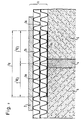
- underground 5 a range of the width l o measures are taken in the illustrated in FIGS. 1 to 4 insulating cover layer structure in each case, by means of which the deformations of the subsoil are recorded in such a manner 5 that this structure, in particular the outer skin 2 is not damaged.
- Fig. 1 it is provided for this purpose, l relapsing soft to bond the insulating layer 3 on both sides of Hauwerksfuge 4 with a width of 0/2 with the substrate. 5
- a soft adhesive layer comes to the width l o or a corresponding layer of a shear-flexible composite mortar, a permanently flexible adhesive layer or a suitable elastomeric layer.
- FIG. 2 shows a two-layer insulation layer in the form of two adjacent insulation layer plates 3a and 3b instead of the single insulation layer plate 3 from FIG. 1.
- This two-layer insulation layer has two decoupling areas 6a and 6b, the decoupling area 6a being provided relative to the concrete base 5, similar to that in FIG. 1, while the second decoupling area 6b additionally decouples the two insulating layer plates 3a and 3b.
- Both decoupling areas 6a and 6b in turn extend on both sides of the structural joint 4 with a total width l o .
- the decoupling areas 6a and 6b like the decoupling area 6 in FIG. 1, can be designed as a flexible zone.
- the composite layers 6a and 6b can optionally be fiber or mat-reinforced. Such reinforcement can also be provided for the composite layer 6 of FIG. 1.
- the Entkoppelungs Club 6a can also be provided as a composite free Entkoppelungs Trial, wherein the composite free area 6a in practice advantageously by the Morrisbe mode of the substrate 3a with adhesive in a range of the total width l o on both sides of the Bauwerksfuge is provided.
- the outer skin or the outer layer is the insulating cover layer structure formed 8 1 elastically, at least in a portion of the total width l o opposite to the Bauwerksfuge 4.
- This area 8 is specially adapted stretchable and preferably mat or fiber-reinforced.
- An elastomer, for example, can be considered as the material for the particularly stretchable region 8.
- Fig. 3 is the insulating layer or under the outer skin 8 Insulation board 3 firmly glued to the concrete base 5, namely also in the critical area of structural joints.
- the insulation board can be used in this critical area Concrete base 5 coupled softly to the base 5 be.
- Fig. 4 instead of the single insulation board 3 a multi-layer insulation board structure can also be used is designed, for example, according to FIG. 2.
Landscapes
- Engineering & Computer Science (AREA)
- Architecture (AREA)
- Civil Engineering (AREA)
- Structural Engineering (AREA)
- Physics & Mathematics (AREA)
- Acoustics & Sound (AREA)
- Electromagnetism (AREA)
- Building Environments (AREA)
Description
Schließlich kommt als schubweicher Verbundbereich auch eine Elastomerschicht in Betracht. Gegebenenfalls ist der schubweiche Verbundbereich faserbewehrt.
Die Maßnahmen zur gleichmäßigen Verteilung der Untergrund-Verformungen können auch darin bestehen, daß innerhalb der Dämmschicht Entkopplungsbereiche vorgesehen sind, die als verbundfreie Zonen oder als schubweiche Zonen im Bereich der Bauwerksfugen ausgebildet sind.
- Fig. 1 bis 3
- jeweils eine Schnittansicht durch den Fugenbereich einer Bauwerksfassade, die mit unterschiedlichen Varianten der erfindungsgemäßen Dämm-Deckschichtstruktur verkleidet ist.
Claims (15)
- Anordnung zum Dämmen und Dichten von Bauwerksfugen aufweisenden Bauwerksfassaden (5) mit einer Fugen überspannenden Dämm-Deckschichtstruktur (1), die eine außenliegende wasserdurchlässige Deckschicht (2) und wenigstens eine innenliegende Dämmschicht (3) aufweist, die an die Deckschicht (2) und die Bauwerksfassade (5) angrenzt,
dadurch gekennzeichnet,
daß ein schubweicher Entkoppelungsbereich (6) der Dämmschicht (3) von vorbestimmter Breite im Bereich der Bauwerksfugen (4) vorgesehen ist, der die in diesem Bereich der Bauwerksfugen (4) auftretenden Verformungen von der Dämm-Deckschichtstruktur (1), insbesondere der Deckschicht (2) fernhält. - Anordnung nach Anspruch 1,
dadurch gekennzeichnet,
daß die schubweiche Schicht eine Klebstoffschicht umfaßt. - Anordnung nach Anspruch 1,
dadurch gekennzeichnet,
daß die schubweiche Schicht eine Elastomerschicht ist. - Anordnung nach Anspruch 1,
dadurch gekennzeichnet,
daß die schubweiche Schicht aus einem schubweichen Verbundmörtel besteht. - Anordnung nach einem oder mehreren der Ansprüche 1 bis 4,
dadurch gekennzeichnet,
daß die schubweiche Schicht faserbewehrt ist. - Anordnung nach einem oder mehreren der Ansprüche 1 bis 5,
dadurch gekennzeichnet,
daß die Dämmschicht (3) mehrere Lagen (3a, 3b) aufweist. - Anordnung nach Anspruch 6,
dadurch gekennzeichnet,
daß die einzelnen Lagen (3a, 3b) im Bereich der Bauwerksfugen (4) verbundfrei untereinander angeordnet sind. - Anordnung nach Anspruch 7,
gekennzeichnet durch
einen verbundfreien Zwischenbereich (6a) in Form einer Trennschicht. - Anordnung nach Anspruch 8,
dadurch gekennzeichnet,
daß die Trennschicht eine mit der unteren Dämmschicht (3a) verbundene Klebefolie oder ein Klebeband ist. - Anordnung nach Anspruch 6,
dadurch gekennzeichnet,
daß die einzelnen Lagen (3a, 3b) im Bereich der Bauwerksfugen (4) schubweich miteinander, sowie mit der Bauwerksfassade (5) verbunden sind. - Anordnung nach Anspruch 10,
dadurch gekennzeichnet,
daß die schubweiche Verbindung eine weiche Klebstoffschicht umfaßt. - Anordnung nach Anspruch 10,
dadurch gekennzeichnet,
daß die schubweiche Verbindung einen schubweichen Verbundmörtel umfaßt. - Anordnung nach Anspruch 10,
dadurch gekennzeichnet,
daß die schubweiche Verbindung eine Elastomerschicht umfaßt. - Anordnung nach Anspruch 10,
dadurch gekennzeichnet,
daß die schubweiche Verbindung eine dauerplastische Klebstoffschicht ist. - Anordnung nach einem oder mehreren der Ansprüche 1 bis 14,
gekennzeichnet durch
einen Verbundentkopplungsbereich und/oder schubweichen Bereich innerhalb der Dämmschicht (3), wobei diese Bereiche parallel zur Bauwerksfassade (5) verlaufend ausgebildet sind.
Applications Claiming Priority (3)
| Application Number | Priority Date | Filing Date | Title |
|---|---|---|---|
| DE4121457A DE4121457C2 (de) | 1991-06-28 | 1991-06-28 | Anordnung und Verfahren zum Dämmen und Dichten von Fugen aufweisenden Bauwerksfassaden |
| DE4121457 | 1991-06-28 | ||
| EP92106684A EP0520152B1 (de) | 1991-06-28 | 1992-04-16 | Anordnung zum Dämmen und Dichten von Fugen aufweisenden Bauwerksfassaden |
Related Parent Applications (3)
| Application Number | Title | Priority Date | Filing Date |
|---|---|---|---|
| EP92106684.1 Division | 1992-04-16 | ||
| EP92106684A Division-Into EP0520152B1 (de) | 1991-06-28 | 1992-04-16 | Anordnung zum Dämmen und Dichten von Fugen aufweisenden Bauwerksfassaden |
| EP92106684A Division EP0520152B1 (de) | 1991-06-28 | 1992-04-16 | Anordnung zum Dämmen und Dichten von Fugen aufweisenden Bauwerksfassaden |
Publications (3)
| Publication Number | Publication Date |
|---|---|
| EP0626487A2 EP0626487A2 (de) | 1994-11-30 |
| EP0626487A3 EP0626487A3 (de) | 1995-04-19 |
| EP0626487B1 true EP0626487B1 (de) | 1999-01-07 |
Family
ID=6435003
Family Applications (2)
| Application Number | Title | Priority Date | Filing Date |
|---|---|---|---|
| EP94111312A Expired - Lifetime EP0626487B1 (de) | 1991-06-28 | 1992-04-16 | Anordnung zum Dämmen und Dichten von Fugen aufweisenden Bauwerksfassaden |
| EP92106684A Expired - Lifetime EP0520152B1 (de) | 1991-06-28 | 1992-04-16 | Anordnung zum Dämmen und Dichten von Fugen aufweisenden Bauwerksfassaden |
Family Applications After (1)
| Application Number | Title | Priority Date | Filing Date |
|---|---|---|---|
| EP92106684A Expired - Lifetime EP0520152B1 (de) | 1991-06-28 | 1992-04-16 | Anordnung zum Dämmen und Dichten von Fugen aufweisenden Bauwerksfassaden |
Country Status (4)
| Country | Link |
|---|---|
| EP (2) | EP0626487B1 (de) |
| AT (2) | ATE175463T1 (de) |
| DE (3) | DE4121457C2 (de) |
| DK (1) | DK0520152T3 (de) |
Families Citing this family (4)
| Publication number | Priority date | Publication date | Assignee | Title |
|---|---|---|---|---|
| DE9408689U1 (de) * | 1994-05-27 | 1994-11-03 | Bösecke, Jürgen, 39114 Magdeburg | Fugenisolation |
| DE4438667C2 (de) * | 1994-10-28 | 2000-05-18 | Fraunhofer Ges Forschung | Aufputzsystem |
| FR2894605B1 (fr) * | 2005-12-09 | 2008-02-01 | Michel Pia | Systeme d'isolation thermique des facades de batiments a base de panneaux composites rigides |
| CN113217633B (zh) * | 2021-05-20 | 2023-06-23 | 中国计量大学 | 具有浮动密封坝的动静压混合式箔片端面气膜密封结构 |
Family Cites Families (10)
| Publication number | Priority date | Publication date | Assignee | Title |
|---|---|---|---|---|
| DE1081205B (de) * | 1956-04-05 | 1960-05-05 | Roland Dachpappenfabrik F Wald | Verfahren zum Isolieren und wasserdichten Abdecken von Bauwerken, insbesondere von Betonflachdaechern |
| FR1438746A (fr) * | 1965-06-14 | 1966-05-13 | Plastiques Et Resines Applique | Construction de chambre étanche, isotherme |
| DE2702198A1 (de) * | 1977-01-20 | 1978-07-27 | Basf Farben & Fasern | Oberflaechenveredeltes bauelement |
| FR2394651A1 (fr) * | 1977-06-17 | 1979-01-12 | Dufour Et Fils Anc Ets Marius | Dispositif permettant de realiser le pontage des joints ou fissures en une seule operation et son procede d'application |
| DE2742337A1 (de) * | 1977-09-20 | 1979-03-29 | Sandell Manufacturing Co | Dehnungsverbindung und kehlblechkonstruktion |
| DE3001140C2 (de) * | 1980-01-14 | 1982-05-19 | Prix-Bauelemente Wiehofsky & Drexl, 8919 Schondorf | Fassaden-Dämmplatte |
| DE3006724A1 (de) * | 1980-02-22 | 1981-09-03 | Dietmar 8184 St Quirin Leffer | Risseabdeckstreifen und verfahren zu dessen herstellung |
| FR2484500A1 (fr) * | 1980-06-17 | 1981-12-18 | Hugot Jeanne | Revetement pour l'isolation exterieure de murs ou analogues |
| FR2539785B1 (fr) * | 1983-01-20 | 1986-01-31 | Strati France | Revetement etanche et isolant pour un support, notamment pour une toiture-terrasse, selon la technique de l'etancheite inversee |
| US4562109A (en) * | 1984-08-31 | 1985-12-31 | The Goodyear Tire & Rubber Company | Crack resistant coating for masonry structures and process for applying same |
-
1991
- 1991-06-28 DE DE4121457A patent/DE4121457C2/de not_active Expired - Fee Related
-
1992
- 1992-04-16 AT AT94111312T patent/ATE175463T1/de not_active IP Right Cessation
- 1992-04-16 DE DE59202674T patent/DE59202674D1/de not_active Expired - Fee Related
- 1992-04-16 EP EP94111312A patent/EP0626487B1/de not_active Expired - Lifetime
- 1992-04-16 EP EP92106684A patent/EP0520152B1/de not_active Expired - Lifetime
- 1992-04-16 AT AT92106684T patent/ATE124490T1/de active
- 1992-04-16 DK DK92106684.1T patent/DK0520152T3/da active
- 1992-04-16 DE DE59209610T patent/DE59209610D1/de not_active Expired - Fee Related
Also Published As
| Publication number | Publication date |
|---|---|
| EP0626487A2 (de) | 1994-11-30 |
| ATE175463T1 (de) | 1999-01-15 |
| DE4121457A1 (de) | 1993-01-14 |
| EP0626487A3 (de) | 1995-04-19 |
| EP0520152A1 (de) | 1992-12-30 |
| DE59202674D1 (de) | 1995-08-03 |
| EP0520152B1 (de) | 1995-06-28 |
| ATE124490T1 (de) | 1995-07-15 |
| DE59209610D1 (de) | 1999-02-18 |
| DE4121457C2 (de) | 1997-02-13 |
| DK0520152T3 (da) | 1995-09-11 |
Similar Documents
| Publication | Publication Date | Title |
|---|---|---|
| DE69907752T2 (de) | Verfahren und vorrichtung zum abdichten von fugen oder rissen in hydraulischen werken, beton und mauerwerk | |
| EP0314830B1 (de) | Wärmedämmaterial als Dämm- und Dichtschicht für Dachflächen | |
| CH669239A5 (de) | Vorrichtung zur ausbildung eines anschlussueberganges zwischen zwei rechtwinklig zueinander stehenden flaechen mit starren belaegen. | |
| EP0520152B1 (de) | Anordnung zum Dämmen und Dichten von Fugen aufweisenden Bauwerksfassaden | |
| DE3509514C2 (de) | Unterdachelement | |
| DE1934995C3 (de) | Abdichtung und Isolierung für einen mit Stahlbetontübbingen ausgebauten Tunnel | |
| DE2925513C2 (de) | Wasserisolierende Abdichtungsschicht für mineralische Oberflächen | |
| DE2306964A1 (de) | Mechanischer fugenverschluss | |
| DE10055354B4 (de) | Plattenelement | |
| DE3823365A1 (de) | Dacheindeckungselement | |
| DE19956834B4 (de) | Verfahren zum Abdichten von Unterspannbahnen | |
| DE9306210U1 (de) | Schutzvorrichtung zur Vermeidung von Baustoffkorrosion | |
| EP0658656A2 (de) | Als wasserdichte Verkleiding für Bauwerkteile dienende flexible Dichtungsbahn | |
| DE3001956A1 (de) | Dachkonstruktion insbesondere fuer flache bzw. flachgeneigte daecher | |
| DE2614529B2 (de) | Isolierverkleidung für Räume | |
| EP1126097A2 (de) | Dachhaut und Verfahren zur Herstellung einer Dachhaut | |
| DE2837333A1 (de) | Abdichtung von wandungen gegen druck- und/oder sickerwasser mit mehrschichtiger dichtungsbahn | |
| DE102004004408A1 (de) | Dämmelement für Bauwerke | |
| DD295406A5 (de) | Dach bzw. dachelement fuer flachdaecher | |
| EP0475218A1 (de) | Fensterbank | |
| DE3408429A1 (de) | Vorgefertigtes element zur dach- und wandverkleidung | |
| DE29601734U1 (de) | Deckleiste für Dehnfugen von Gebäuden | |
| EP0347564B1 (de) | Plattenelement für die Herstellung von Gebäudedächern | |
| DE4313466A1 (de) | Schutzvorrichtung zur Vermeidung von Baustoffkorrosion | |
| EP1290284B1 (de) | Spaltabdichtung an bauwerken |
Legal Events
| Date | Code | Title | Description |
|---|---|---|---|
| PUAI | Public reference made under article 153(3) epc to a published international application that has entered the european phase |
Free format text: ORIGINAL CODE: 0009012 |
|
| AC | Divisional application: reference to earlier application |
Ref document number: 520152 Country of ref document: EP |
|
| AK | Designated contracting states |
Kind code of ref document: A2 Designated state(s): AT BE CH DE DK FR LI LU SE |
|
| 17P | Request for examination filed |
Effective date: 19941019 |
|
| PUAL | Search report despatched |
Free format text: ORIGINAL CODE: 0009013 |
|
| AK | Designated contracting states |
Kind code of ref document: A3 Designated state(s): AT BE CH DE DK FR LI LU SE |
|
| 17Q | First examination report despatched |
Effective date: 19960711 |
|
| GRAG | Despatch of communication of intention to grant |
Free format text: ORIGINAL CODE: EPIDOS AGRA |
|
| GRAG | Despatch of communication of intention to grant |
Free format text: ORIGINAL CODE: EPIDOS AGRA |
|
| GRAH | Despatch of communication of intention to grant a patent |
Free format text: ORIGINAL CODE: EPIDOS IGRA |
|
| GRAH | Despatch of communication of intention to grant a patent |
Free format text: ORIGINAL CODE: EPIDOS IGRA |
|
| GRAA | (expected) grant |
Free format text: ORIGINAL CODE: 0009210 |
|
| AC | Divisional application: reference to earlier application |
Ref document number: 520152 Country of ref document: EP |
|
| AK | Designated contracting states |
Kind code of ref document: B1 Designated state(s): AT BE CH DE DK FR LI LU SE |
|
| PG25 | Lapsed in a contracting state [announced via postgrant information from national office to epo] |
Ref country code: SE Free format text: THE PATENT HAS BEEN ANNULLED BY A DECISION OF A NATIONAL AUTHORITY Effective date: 19990107 Ref country code: FR Free format text: LAPSE BECAUSE OF FAILURE TO SUBMIT A TRANSLATION OF THE DESCRIPTION OR TO PAY THE FEE WITHIN THE PRESCRIBED TIME-LIMIT Effective date: 19990107 |
|
| REF | Corresponds to: |
Ref document number: 175463 Country of ref document: AT Date of ref document: 19990115 Kind code of ref document: T |
|
| REG | Reference to a national code |
Ref country code: CH Ref legal event code: EP |
|
| REF | Corresponds to: |
Ref document number: 59209610 Country of ref document: DE Date of ref document: 19990218 |
|
| PG25 | Lapsed in a contracting state [announced via postgrant information from national office to epo] |
Ref country code: DK Free format text: LAPSE BECAUSE OF FAILURE TO SUBMIT A TRANSLATION OF THE DESCRIPTION OR TO PAY THE FEE WITHIN THE PRESCRIBED TIME-LIMIT Effective date: 19990407 |
|
| PG25 | Lapsed in a contracting state [announced via postgrant information from national office to epo] |
Ref country code: LU Free format text: LAPSE BECAUSE OF NON-PAYMENT OF DUE FEES Effective date: 19990416 Ref country code: AT Free format text: LAPSE BECAUSE OF NON-PAYMENT OF DUE FEES Effective date: 19990416 |
|
| PG25 | Lapsed in a contracting state [announced via postgrant information from national office to epo] |
Ref country code: LI Free format text: LAPSE BECAUSE OF NON-PAYMENT OF DUE FEES Effective date: 19990430 Ref country code: CH Free format text: LAPSE BECAUSE OF NON-PAYMENT OF DUE FEES Effective date: 19990430 Ref country code: BE Free format text: LAPSE BECAUSE OF NON-PAYMENT OF DUE FEES Effective date: 19990430 |
|
| EN | Fr: translation not filed | ||
| K2C3 | Correction of patent specification (complete document) published |
Effective date: 19990107 |
|
| BERE | Be: lapsed |
Owner name: DYCKERHOFF A.G. Effective date: 19990430 |
|
| PLBE | No opposition filed within time limit |
Free format text: ORIGINAL CODE: 0009261 |
|
| STAA | Information on the status of an ep patent application or granted ep patent |
Free format text: STATUS: NO OPPOSITION FILED WITHIN TIME LIMIT |
|
| REG | Reference to a national code |
Ref country code: CH Ref legal event code: PL |
|
| 26N | No opposition filed | ||
| PGFP | Annual fee paid to national office [announced via postgrant information from national office to epo] |
Ref country code: DE Payment date: 20000629 Year of fee payment: 9 |
|
| PG25 | Lapsed in a contracting state [announced via postgrant information from national office to epo] |
Ref country code: DE Free format text: LAPSE BECAUSE OF NON-PAYMENT OF DUE FEES Effective date: 20020201 |