EP0617947B1 - Drehteller für Behinderte - Google Patents
Drehteller für Behinderte Download PDFInfo
- Publication number
- EP0617947B1 EP0617947B1 EP93104198A EP93104198A EP0617947B1 EP 0617947 B1 EP0617947 B1 EP 0617947B1 EP 93104198 A EP93104198 A EP 93104198A EP 93104198 A EP93104198 A EP 93104198A EP 0617947 B1 EP0617947 B1 EP 0617947B1
- Authority
- EP
- European Patent Office
- Prior art keywords
- plate
- rotary
- rotary plate
- base
- hole
- Prior art date
- Legal status (The legal status is an assumption and is not a legal conclusion. Google has not performed a legal analysis and makes no representation as to the accuracy of the status listed.)
- Expired - Lifetime
Links
Images


Classifications
-
- A—HUMAN NECESSITIES
- A61—MEDICAL OR VETERINARY SCIENCE; HYGIENE
- A61G—TRANSPORT, PERSONAL CONVEYANCES, OR ACCOMMODATION SPECIALLY ADAPTED FOR PATIENTS OR DISABLED PERSONS; OPERATING TABLES OR CHAIRS; CHAIRS FOR DENTISTRY; FUNERAL DEVICES
- A61G7/00—Beds specially adapted for nursing; Devices for lifting patients or disabled persons
- A61G7/10—Devices for lifting patients or disabled persons, e.g. special adaptations of hoists thereto
- A61G7/1001—Devices for lifting patients or disabled persons, e.g. special adaptations of hoists thereto specially adapted for specific applications
- A61G7/1003—Devices for lifting patients or disabled persons, e.g. special adaptations of hoists thereto specially adapted for specific applications mounted on or in combination with a bath-tub
-
- A—HUMAN NECESSITIES
- A61—MEDICAL OR VETERINARY SCIENCE; HYGIENE
- A61G—TRANSPORT, PERSONAL CONVEYANCES, OR ACCOMMODATION SPECIALLY ADAPTED FOR PATIENTS OR DISABLED PERSONS; OPERATING TABLES OR CHAIRS; CHAIRS FOR DENTISTRY; FUNERAL DEVICES
- A61G7/00—Beds specially adapted for nursing; Devices for lifting patients or disabled persons
- A61G7/10—Devices for lifting patients or disabled persons, e.g. special adaptations of hoists thereto
- A61G7/1025—Lateral movement of patients, e.g. horizontal transfer
- A61G7/1034—Rollers, rails or other means
-
- A—HUMAN NECESSITIES
- A61—MEDICAL OR VETERINARY SCIENCE; HYGIENE
- A61G—TRANSPORT, PERSONAL CONVEYANCES, OR ACCOMMODATION SPECIALLY ADAPTED FOR PATIENTS OR DISABLED PERSONS; OPERATING TABLES OR CHAIRS; CHAIRS FOR DENTISTRY; FUNERAL DEVICES
- A61G7/00—Beds specially adapted for nursing; Devices for lifting patients or disabled persons
- A61G7/10—Devices for lifting patients or disabled persons, e.g. special adaptations of hoists thereto
- A61G7/1049—Attachment, suspending or supporting means for patients
- A61G7/1059—Seats
-
- A—HUMAN NECESSITIES
- A61—MEDICAL OR VETERINARY SCIENCE; HYGIENE
- A61G—TRANSPORT, PERSONAL CONVEYANCES, OR ACCOMMODATION SPECIALLY ADAPTED FOR PATIENTS OR DISABLED PERSONS; OPERATING TABLES OR CHAIRS; CHAIRS FOR DENTISTRY; FUNERAL DEVICES
- A61G7/00—Beds specially adapted for nursing; Devices for lifting patients or disabled persons
- A61G7/10—Devices for lifting patients or disabled persons, e.g. special adaptations of hoists thereto
- A61G7/1073—Parts, details or accessories
- A61G7/1076—Means for rotating around a vertical axis
Definitions
- the invention relates to a turntable for the disabled, with a guide device on which a rotating plate is displaceable between two end positions and rotatably mounted in at least one of its two end positions, with a locking bolt which immovably holds the rotating plate in at least one of the sliding end positions.
- Such a turntable is known from US-A-5,068,930. Thanks to the locking device, unintentional shifting of the rotating plate from the sliding end position is excluded. The rotatability of the turntable is retained.
- the guide device consists of a frame having rails, which in turn is supported by a frame.
- the turntable is part of a chair that e.g. can be placed in a bathtub. Due to the high construction, this turntable cannot be used in conjunction with a lift or lower bath lift or in a hospital bed.
- EP-A-364 746 shows a flat turntable, but the turntable is immovable.
- the object of the invention is to design a turntable of the type mentioned in such a way that it has the flatest possible construction and is also suitable as a standing surface for rotating and moving disabled people and which consists of a few plastic parts, is inexpensive to manufacture and can be operated by the disabled person allowed yourself.
- the guide device is designed as an elongated base plate, the length measured in the sliding direction is at least about twice as large as the diameter of the rotating plate and which has a central longitudinal channel in which a circularly contoured sliding plate provided on the underside of the rotating plate rotates and longitudinally engages that the Rotary plate and the sliding plate each have a hole open at the bottom, which is arranged coaxially to the axis of rotation, that a bottom hole is provided in the bottom wall of the longitudinal channel, which is aligned with the hole and that of the sliding plate in a sliding end position of the rotating plate, and that the locking bolt in the Holes of the rotary plate and the sliding plate is axially displaceably mounted and engages in the bottom end position of the rotating plate in the bottom hole of the bottom plate.
- the invention makes it possible to open the shifting function only temporarily, namely for the transport of a disabled person, but to lock the rotary plate again in the sliding end position in such a way that it can then only be rotated.
- Such a function is e.g. advantageous in connection with bath lifts.
- the turntable can be e.g. also use in bed to move and turn patients. But also in connection with bath lifts, the invention has great advantages, since the maximum immersion depth of the disabled person sitting on the turntable is hardly reduced.
- a turntable 10 has a base plate 12, a turntable 14 with a cushion pad 16 and a retaining ring 18.
- a sliding plate 20 is screwed onto the underside of the rotary plate 14.
- the base plate 12 is elongated and is contoured by two semicircular arches and straight lines connecting them. The diameter of the semicircular arches corresponds to that of the rotary plate 14 equipped with the retaining ring 18.
- the circularly contoured sliding plate is rotatably and displaceably guided in this guideway 22.
- the sliding plate 20 has a diameter on the top side equal to the clear width of the guide track 22.
- the sliding plate 20 has an outer flange 24 which engages in an all-round recess 26 of the base plate 12.
- the sliding plate is fastened to the bottom of the rotary plate 14 by means of screws 28.
- In the middle of the guideway 22 there is a recess 28 (FIG. 2) on one side in the top wall, which serves to insert the sliding plate 20 into the guideway 22.
- a hole 30 is provided in the base plate 12 at both ends within the guideway 22. The holes are located in the longitudinal median plane and are concentric with the semicircular contours of the base plate 12.
- the rotating plate 14 and the sliding plate 20 have through holes 32, 34 of the same diameter which are aligned with one another. These through holes 32, 34 are coaxial to the axis of rotation of the rotary plate 14. In the two sliding end positions of the rotary plate 14, the pair of bores 32, 34 are aligned with the respective hole 30 in the base plate 12.
- a bolt 36 is axially displaceably guided in the bore arrangement 32, 34. In the central region, the bolt 36 has two axially spaced circumferential grooves 38. From the top side of the sliding plate 20, two opposing recesses 40 are provided in these two pairs, in which spring wires 42 are supported with their ends. Two recesses 40 are connected to one another by a recess 44 of the same depth as the recesses 40. The transverse spacing of the two pairs of recesses 40, 40 is slightly less than the core diameter of the bolt 36 in the region of the ring grooves 38. The spring wires 42 engage in one or the other groove 38 under slight prestress.
- the bolt 36 is shown in FIG. 3 shown in its unlocked position. If a downward pressure is exerted on the mat 16 in the center region of the rotary plate 14, the spring wires 42 yield into the recesses 44 due to the V-shaped contour of the ring grooves 38. The bolt can then move downward until the spring wires 42 snap into the upper annular groove 38. The lower end of the bolt has then entered the hole 30 of the base plate 12 and the rotary plate 14 is locked against displacement in the respective setting of the base plate. Since the hole 30 is open at the bottom, the bolt 36 can be pushed up into its unlocked position and locked by means of a corresponding finger pressure from below.
- the base plate 12 has groups of transverse grooves 46 which result in articulated webs 48 which allow the base plate 12 to be bent.
- a plurality of anti-slip strips 50 are arranged on the base plate 12 and are preferably inserted in a form-fitting manner in corresponding base recesses in the base plate 12.
- FIG. 5 shows a modification of the locking device for the rotary plate 14.
- the bolt 36 ' here has only one annular groove for the pair of spring wires 42.
- the bolt 36' has a cover-side outer flange on which a compression spring 52 is supported, which is supported on the bottom side on the sliding plate 20.
- FIG. 5 shows the bolt 36 ′ in the locking position, in which it plunges into the hole 30 in the base plate 12. If one now presses the upholstery mat 16 in the center region of the rotary plate 14, the bolt 36 ′ is completely immersed in the hole 30, the spring wires 42 being pressed outwards into the recesses 44. The compression spring 52 is compressed. If you now let go of the bolt 36 ', the bolt 36' moves upwards due to the strong spring force. The spring wires 42 penetrate briefly into the annular groove 38, but cannot brake the bolt 36 'due to the dynamics. The bolt 36 'thus runs over this locking position and reaches its unlocking position on the underside of the cushion mat 16.
- the execution according to FIG. 5 thus allows the rotary plate 14 to be locked from above by a metered pressure on the bolt 36 'and also to be unlocked by a pressure in the same direction.
- This version is chosen when a turntable is to enable locking and unlocking with a person sitting on it.
- FIG. 6 shows yet another modification which ensures that the rotary plate 14 is automatically locked and unlocked.
- the bolt 36 '' no longer has a ring groove here. It is pot-shaped and a spring 54 biases the bolt 36 '' downward into the locking position.
- the rotary plate 14 does not have a through hole 32 but a blind hole 56 closed on the top side, so that the compression spring 54 can be supported on the top of the rotary plate 14.
- An obliquely rising ramp section 58 which runs into the bottom surface of the guideway 22, adjoins the hole 30 of the base plate 12 in the longitudinal direction of the base plate 12. The width of this ramp area corresponds to the diameter of the bore 30.
- the bolt 36 is arranged centrally in the rotary plate 14.
- the rotary plate 14 is thus locked in its two end positions, or at least in one setting, so that it cannot slide, but can be rotated.
Landscapes
- Health & Medical Sciences (AREA)
- Nursing (AREA)
- Life Sciences & Earth Sciences (AREA)
- Animal Behavior & Ethology (AREA)
- General Health & Medical Sciences (AREA)
- Public Health (AREA)
- Veterinary Medicine (AREA)
- Seats For Vehicles (AREA)
- Devices For Medical Bathing And Washing (AREA)
- Bathtubs, Showers, And Their Attachments (AREA)
- Holding Or Fastening Of Disk On Rotational Shaft (AREA)
- Invalid Beds And Related Equipment (AREA)
- Vehicle Cleaning, Maintenance, Repair, Refitting, And Outriggers (AREA)
- Chairs For Special Purposes, Such As Reclining Chairs (AREA)
- Load-Engaging Elements For Cranes (AREA)
- Forklifts And Lifting Vehicles (AREA)
- Toilet Supplies (AREA)
- Multiple-Way Valves (AREA)
- Centrifugal Separators (AREA)
- Accommodation For Nursing Or Treatment Tables (AREA)
- Valve-Gear Or Valve Arrangements (AREA)
- Tents Or Canopies (AREA)
- Mechanical Treatment Of Semiconductor (AREA)
- Air-Conditioning For Vehicles (AREA)
- Automatic Analysis And Handling Materials Therefor (AREA)
- Tables And Desks Characterized By Structural Shape (AREA)
- Pinball Game Machines (AREA)
- Sawing (AREA)
- Finish Polishing, Edge Sharpening, And Grinding By Specific Grinding Devices (AREA)
Description
- Die Erfindung betrifft einen Drehteller für Behinderte, mit einer Führungseinrichtung, auf der eine Drehplatte zwischen zwei Endstellungen verschiebbar und in mindestens einer ihrer beiden Endstellungen drehbar gelagert ist, mit einem Arretierbolzen, welcher die Drehplatte in mindestens einer der Schiebeendstellungen unverschiebbar festhält.
- Ein derartiger Drehteller ist aus der US-A-5,068,930 bekannt. Dank der Arretiereinrichtung ist ein ungewolltes Verschieben der Drehplatte aus der Schiebeendstellung ausgeschlossen. Die Drehbarkeit der Drehplatte bleibt aber erhalten. Die Führungseinrichtung besteht aus einem Schienen aufweisenden Rahmen, der seinerseits von einem Gestell getragen wird. Der Drehteller ist Bestandteil eines Stuhles der z.B. in eine Badewanne eingestellt werden kann. Wegen der hohen Bauweise ist dieser Drehteller nicht in Verbindung mit einem heb- oder senkbaren Badelifter oder in einem Krankenbett verwendbar.
- Die EP-A-364 746 zeigt einen flachbauenden Drehteller, dessen Drehplatte aber unverschiebbar ist.
- Aufgabe der Erfindung ist es, einen Drehteller der eingangs genannten Art so auszubilden, daß er eine möglichst flache Bauweise aufweist und auch als Standfläche zum Drehen und Verschieben von Behinderten geeignet ist und der aus wenigen Kunststoffteilen besteht, kostengünstig herstellbar ist und eine Bedienung durch den Behinderten selbst erlaubt.
- Gemäß der Erfindung ist vorgesehen, daß die Führungseinrichtung als längliche Bodenplatte ausgebildet ist, deren in Schieberichtung gemessene Länge mindestens etwa doppelt so groß ist wie der Durchmesser der Drehplatte und die einen mittigen Längskanal aufweist, in welchem eine an der Unterseite der Drehplatte vorgesehene kreisförmig konturierte Schiebeplatte drehbar und längsverschiebbar eingreift, daß die Drehplatte und die Schiebeplatte je ein unten offenes Loch aufweisen, das koaxial zur Drehachse angeordnet ist, daß in der Bodenwand des Längskanals ein Bodenloch vorgesehen ist, das in einer Schiebeendstellung der Drehplatte mit deren Loch und dem der Schiebeplatte fluchtet, und daß der Arretierbolzen in den Löchern der Drehplatte und der Schiebeplatte axial verschiebbar gelagert ist und in der einen Schiebeendstellung der Drehplatte in das Bodenloch der Bodenplatte eingreift.
- Die Erfindung ermöglicht es, die Verschiebefunktion nur vorübergehend, nämlich für den Transport eines Behinderten zu eröffnen, in der Schiebeendstellung die Drehplatte jedoch wieder zu arretieren, derart, daß diese dann nur noch drehbar ist. Eine solche Funktion ist z.B. in Verbindung mit Badeliftern vorteilhaft.
- Dank der extrem flachen Bauweise von insgesamt nur etwa 10 mm Höhe läßt sich der Drehteller z.B. auch im Bett zum Verschieben und Drehen von Patienten verwenden. Aber auch in Verbindung mit Badeliftern bringt die Erfindung große Vorteile, da die maximale Eintauchtiefe des auf dem Drehteller sitzenden Behinderten kaum reduziert wird.
- Ausgestaltungen und Weiterbildungen der Erfindung bilden die Gegenstände der Unteransprüche.
- Anhand der Zeichnung, die einige Ausführungsbeispiele darstellt, wird diese Erfindung näher beschrieben.
- Es zeigt:
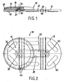
- FIG. 1
- eine teilweise geschnittene Längsansicht des Drehtellers,
- FIG. 2
- eine Draufsicht aud den Drehteller,
- FIG. 3
- eine vergrößerte Schnittansicht der zentralen Arretiereinrichtung des Drehtellers,
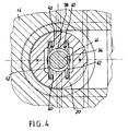
- FIG. 4
- eine horizontale Schnittansicht längs der Linie 4-4 der FIG. 3,
- FIG. 5
- eine Schnittansicht ähnlich FIG. 3, jedoch durch eine alternative Ausführungsform, und
- FIG. 6
- eine Schnittansicht durch eine weitere Ausführungsform der Erfindung.
- Ein Drehteller 10 weist eine Bodenplatte 12, eine Drehplatte 14 mit Polsterauflagematte 16 und Haltering 18 auf. An der Unterseite der Drehplatte 14 ist eine Schiebeplatte 20 angeschraubt. Grundsätzlich könnten Drehplatte 14 und Schiebeplatte 20 auch einstückig ausgebildet sein. Die Bodenplatte 12 ist länglich und wird durch zwei Halbkreisbogen sowie diese miteinander verbindende Geraden konturiert. Der Durchmesser der Halbkreisbogen entspricht demjenigen der mit dem Haltering 18 ausgestatteten Drehplatte 14. Deckseitig befindet sich in der Bodenplatte 12 eine oben offene Führungsbahn, 22, die einen T-Nut-Querschnitt aufweist. In dieser Führungsbahn 22 ist die kreisförmig konturierte Schiebeplatte drehbar und verschiebbar geführt. Die Schiebeplatte 20 hat deckseitig einen Durchmesser gleich der lichten Weite der Führungsbahn 22. In der unteren Hälfte weist die Schiebeplatte 20 einen Außenflansch 24 auf, der in eine ringsum laufende Freisparung 26 der Bodenplatte 12 eingreift. Die Schiebeplatte ist mittels Schrauben 28 bodenseitig an der Drehplatte 14 befestigt. In der Mitte der Führungsbahn 22 befindet sich an einer Seite in der Deckwand eine Aussparung 28 (FIG. 2), die zum Einführen der Schiebeplatte 20 in die Führungsbahn 22 dient. Innerhalb der Führungsbahn 22 ist an beiden Enden jeweils ein Loch 30 in der Bodenplatte 12 vorgesehen. Die Löcher befinden sich in der Längsmittelebene und liegen konzentrisch zu den Halbrundkonturen der Bodenplatte 12.
- Die Drehplatte 14 und die Schiebeplatte 20 haben miteinander fluchtende Durchgangsbohrungen 32, 34 gleichen Durchmessers. Diese Durchgangsbohrungen 32, 34 liegen koaxial zur Rotationsachse der Drehplatte 14. In den beiden Schiebeendstellungen der Drehplatte 14 fluchtet das Bohrungspaar 32, 34 mit dem jeweiligen Loch 30 in der Bodenplatte 12. In der Bohrungsanordnung 32, 34 ist ein Bolzen 36 axial verschiebbar geführt. Im Mittelbereich weist der Bolzen 36 zwei axial beabstandete Umfangsnuten 38 auf. Von der Deckseite der Schiebeplatte 20 her sind in diese zwei Paare einander gegenüberliegende Vertiefungen 40 vorgesehen, in denen Federdrähte 42 mit ihren Enden gelagert sind. Je zwei Vertiefungen 40 sind durch eine Aussparung 44 von gleicher Tiefe wie die Vertiefungen 40 miteinander verbunden. Der Querabstand der beiden Vertiefungspaare 40, 40 ist etwas geringer als der Kerndurchmesser des Bolzens 36 im Bereich der Ringnuten 38. Die Federdrähte 42 greifen unter leichter Vorspannung wahlweise in eine oder die andere Nut 38 ein.
- Der Bolzen 36 ist in FIG. 3 in seiner Entriegelungsstellung gezeigt. Wird auf die Matte 16 im Zentrumsbereich der Drehplatte 14 ein abwärts gerichteter Druck ausgeübt, so weichen die Federdrähte 42 aufgrund der V-förmigen Kontur der Ringnuten 38 in die Aussparungen 44 aus. Der Bolzen kann sich dann abwärts bewegen, bis die Federdrähte 42 in die obere Ringnut 38 einrasten. Das untere Ende des Bolzens ist dann in das Loch 30 der Bodenplatte 12 eingetreten und die Drehplatte 14 ist in der jeweiligen Enstellung der Bodenplatte verschiebesicher verriegelt. Da das Loch 30 bodenseitig offen ist, kann mittels eines entsprechenden Fingerdruckes von unten der Bolzen 36 wieder in seine Entriegelungsstellung hochgeschoben und verrastet werden.
- Die Bodenplatte 12 weist Gruppen von Quernuten 46 auf, die Gelenkstege 48 ergeben, die ein Biegen der Bodenplatte 12 gestatten.
- Bodenseitig sind an der Bodenplatte 12 mehrere Antirutschstreifen 50 angeordnet und vorzugsweise formschlüssig in entsprechenden Bodenaussparungen der Bodenplatte 12 eingelassen.
- In FIG. 5 ist eine Abwandlung der Arretierungseinrichtung für die Drehplatte 14 gezeigt. Der Bolzen 36' hat hier nur eine Ringnut für das Paar Federdrähte 42. Der Bolzen 36' hat einen deckseitigen Außenflansch, an dem sich eine Druckfeder 52 abstützt, die bodenseitig an der Schiebeplatte 20 abgestützt ist. FIG. 5 zeigt den Bolzen 36' in der Verriegelungsstellung, in welcher er in das Loch 30 der Bodenplatte 12 eintaucht. Drückt man nun von oben auf die Polstermatte 16 im Zentrumsbereich der Drehplatte 14, so taucht der Bolzen 36' ganz in das Loch 30 ein, wobei die Federdrähte 42 nach außen in die Aussparungen 44 gedrückt werden. Die Druckfeder 52 wird dabei komprimiert. Läßt man nun den Bolzen 36' los, so bewegt sich der Bolzen 36' aufgrund der starken Federkraft nach oben. Die Federdrähte 42 dringen zwar kurzfristig in die Ringnut 38 ein, können aber den Bolzen 36' aufgrund der Dynamik nicht bremsen. Der Bolzen 36' überfährt also diese Raststellung und gelangt in seine Entriegelungsstellung an der Unterseite der Polstermatte 16.
- Die Ausführung gemäß FIG. 5 erlaubt es also, durch einen dosierten Druck auf den Bolzen 36' von oben her die Drehplatte 14 zu verriegeln und durch einen Druck in derselben Richtung auch die Entriegelung zu bewirken. Diese Ausführung wird also dann gewählt, wenn ein Drehteller die Verriegelung und Entriegelung mit einer darauf sitzenden Person ermöglichen soll.
- FIG. 6 zeigt eine noch weitere Abwandlung, die eine selbsttätige Verriegelung und Entriegelung der Drehplatte 14 gewährleistet. Der Bolzen 36'' weist hier keine Ringut mehr auf. Er ist topfartig ausgebildet und eine Feder 54 spannt den Blzen 36'' nach unten in die Verriegelungsstellung vor. Die Drehplatte 14 weist keine durchgehende Bohrung 32 sondern ein deckseitig geschlossenes Sackloch 56 auf, sodaß sich die Druckfeder 54 oben an der Drehplatte 14 abstützen kann. An das Loch 30 der Bodenplatte 12 schießt sich in Längsrichtung der Bodenplatte 12 ein schräg ansteigender Rampenabschnitt 58 an, der in die Bodenfläche der Führungsbahn 22 einläuft. Die Breite dieser Rampenfläche entspricht dem Druchmesser der Bohrung 30. Wird auf die Drehplatte 14 in Längsrichtung eine Schiebekraft ausgeübt, so gleitet der Bolzen 36'' nach Überwindung eines Anfangswiderstandes auf der Rampenfläche 58 entlang, wobei er aus seiner Verriegelungsstellung in die Entriegelungsstellung angehoben wird. Diese Entriegelungsstellung wird durch die Bodenfläche der Führungsbahn 22 definiert, auf der der Bolzen 36'' entlanggleitet. Die untere Umfangskante des Bolzens 36'' ist vorzugsweise angefast, sodaß ein sicheres Auflaufen auf die Rampe 58 gewährleistet ist.
- In allen vorbeschriebenen Ausführungsformen ist der Bolzen 36 zentral in der Drehplatte 14 angeordnet. Die Drehplatte 14 wird damit in ihren beiden Endstelungen oder wenigstens in einer Enstellung schiebesicher, jedoch drehbar arretiert.
Claims (6)
- Drehteller für Behinderte, mit einer Führungseinrichtung, auf der eine Drehplatte (14) zwischen zwei Endstellungen verschiebbar und in mindestens einer ihrer beiden Endstellungen drehbar gelagert ist, mit einem Arretierbolzen (36 36', 36'') welcher die Drehplatte (14) in mindestens einer der Schiebeendstellungen unverschiebbar festhält, dadurch gekennzeichnet, daß die Führungseinrichtung als längliche Bodenplatte (12) ausgebildet ist, deren in Schieberichtung gemessene Länge mindestens etwa doppelt so groß ist wie der Durchmesser der Drehplatte (14) und die einen mittigen Längskanal (22) aufweist, in welchem eine an der Unterseite der Drehplatte (14) vorgesehene kreisförmig konturierte Schiebeplatte (20) drehbar und längsverschiebbar eingreift, daß die Drehplatte (14) und die Schiebeplatte (20) je ein unten offenes Loch (32, 34) aufweisen, das koaxial zur Drehachse angeordnet ist, daß in der Bodenwand des Längskanals (22) ein Bodenloch (30) vorgesehen ist, das in einer Schiebeendstellung der Drehplatte (14) mit deren Loch (32) und dem der Schiebeplatte (20) fluchtet, und daß der Arretierbolzen (36, 36', 36'') in den Löchern (32, 34) der Drehplatte (14) und der Schiebeplatte (20) axial verschiebbar gelagert ist und in der einen Schiebeendstellung der Drehplatte (14) in das Bodenloch (30) der Bodenplatte (12) eingreift.
- Drehteller nach Anspruch 1, dadurch gekennzeichnet, daß das Loch (32) in der Drehplatte (14) an deren Deckseite offen ist und der Arretierbolzen (36) zwei Raststellungen aufweist, in denen er wahlweise mittels einer Federanordnung (42) gehalten ist und daß die beiden Stirnflächen des Bolzens (36) Fingerbetätigungsflächen bilden.
- Drehteller nach Anspruch 1 oder 2, dadurch gekennzeichnet, daß der Bolzen (36') ständig von einer eingebauten axial wirkenden Rückholfeder (52) in Entriegelungsstellung zur Deckseite hin vorgespannt ist, und daß die Federanordnung (42) so ausgebildet ist, daß der Bolzen (36') nach Überfahren seiner unteren Raststellung in Abwärtsrichtung und anschließendem Loslassen durch die Rückholfeder (52) in seine Entriegelungsstellung gelangt.
- Drehteller nach Anspruch 1 oder 2, dadurch gekennzeichnet, daß der Bolzen ständig von einer eingebauten axial wirkenden Feder (54) in Verriegelungsstellung vorgespannt ist und beim Verschieben der Drehplatte (14) mit seiner unteren Stirnfläche auf der Bodenwand des Längskanals (20) entlanggleitet und in der Endstellung der Drehplatte (14) selbsttätig in das Bodenloch (30) der Bodenplatte (12) einrastet.
- Drehteller nach Anspruch 4, dadurch gekennzeichnet, daß in der Bodenwand der Bodenplatte (12) eine, an das Bodenloch (30) anschließende schräge Anlauframpe (58) ausgebildet ist, längs welcher der Bolzen (36'') nach Überwindung eines Anfangswiderstandes beim Verschieben der Drehplatte (14) selbsttätig in Entriegelungsstellung angehoben wird.
- Drehteller nach einem der Ansprüche 1 bis 5, dadurch gekennzeichnet, daß die Bodenplatte (12) zwei spiegelsymmetrische Längshälften aufweist.
Priority Applications (22)
| Application Number | Priority Date | Filing Date | Title |
|---|---|---|---|
| DK93104198.2T DK0617947T3 (da) | 1993-03-16 | 1993-03-16 | Drejetallerken til handicappede |
| EP94100547A EP0633010B1 (de) | 1993-03-16 | 1993-03-16 | Drehteller als Sitzfläche für Behinderte |
| DE59300073T DE59300073D1 (de) | 1993-03-16 | 1993-03-16 | Drehteller für Behinderte. |
| AT94100547T ATE127006T1 (de) | 1993-03-16 | 1993-03-16 | Drehteller als sitzfläche für behinderte. |
| DE59300542T DE59300542D1 (de) | 1993-03-16 | 1993-03-16 | Drehteller als Sitzfläche für Behinderte. |
| EP93104198A EP0617947B1 (de) | 1993-03-16 | 1993-03-16 | Drehteller für Behinderte |
| ES93104198T ES2067340T3 (es) | 1993-03-16 | 1993-03-16 | Plato giratorio para personas impedidas. |
| ES94100547T ES2076840T3 (es) | 1993-03-16 | 1993-03-16 | Plato de giro como superficie de asiento para impedido |
| AT93104198T ATE117534T1 (de) | 1993-03-16 | 1993-03-16 | Drehteller für behinderte. |
| DK94100547.2T DK0633010T3 (da) | 1993-03-16 | 1993-03-16 | Drejetallerken som siddeflade for handicappede |
| US08/205,942 US5390378A (en) | 1993-03-16 | 1994-03-02 | Bathtub seat arrangement for handicapped persons |
| ZA941567A ZA941567B (en) | 1993-03-16 | 1994-03-07 | Bathtub seat arrangement for handicapped persons |
| ZA941600A ZA941600B (en) | 1993-03-16 | 1994-03-08 | Rotatable and displaceable seat |
| AU57695/94A AU663842B2 (en) | 1993-03-16 | 1994-03-09 | Rotatable and displaceable seat |
| AU57692/94A AU666254B2 (en) | 1993-03-16 | 1994-03-09 | Bathtub seat arrangement for handicapped persons |
| US08/212,369 US5390978A (en) | 1993-03-16 | 1994-03-14 | Rotatable and displaceable seat |
| CA 2119040 CA2119040A1 (en) | 1993-03-16 | 1994-03-15 | Rotatable and displaceable seat |
| CA002119041A CA2119041A1 (en) | 1993-03-16 | 1994-03-15 | Bathtub seat arrangement for handicapped persons |
| JP7163794A JPH0747100A (ja) | 1993-03-16 | 1994-03-16 | 身体障害者用の着座面としての回転ならびに移動のできる板装置 |
| JP6071636A JPH06296647A (ja) | 1993-03-16 | 1994-03-16 | 軌道の備わる身体障害者用座席 |
| GR950400252T GR3015010T3 (en) | 1993-03-16 | 1995-02-08 | Turning plate for disabled persons. |
| GR950402507T GR3017389T3 (en) | 1993-03-16 | 1995-09-13 | Turning plate as a seat for disabled persons. |
Applications Claiming Priority (1)
| Application Number | Priority Date | Filing Date | Title |
|---|---|---|---|
| EP93104198A EP0617947B1 (de) | 1993-03-16 | 1993-03-16 | Drehteller für Behinderte |
Related Child Applications (1)
| Application Number | Title | Priority Date | Filing Date |
|---|---|---|---|
| EP94100547.2 Division-Into | 1994-01-15 |
Publications (2)
| Publication Number | Publication Date |
|---|---|
| EP0617947A1 EP0617947A1 (de) | 1994-10-05 |
| EP0617947B1 true EP0617947B1 (de) | 1995-01-25 |
Family
ID=8212697
Family Applications (2)
| Application Number | Title | Priority Date | Filing Date |
|---|---|---|---|
| EP93104198A Expired - Lifetime EP0617947B1 (de) | 1993-03-16 | 1993-03-16 | Drehteller für Behinderte |
| EP94100547A Expired - Lifetime EP0633010B1 (de) | 1993-03-16 | 1993-03-16 | Drehteller als Sitzfläche für Behinderte |
Family Applications After (1)
| Application Number | Title | Priority Date | Filing Date |
|---|---|---|---|
| EP94100547A Expired - Lifetime EP0633010B1 (de) | 1993-03-16 | 1993-03-16 | Drehteller als Sitzfläche für Behinderte |
Country Status (11)
| Country | Link |
|---|---|
| US (2) | US5390378A (de) |
| EP (2) | EP0617947B1 (de) |
| JP (1) | JPH06296647A (de) |
| AT (2) | ATE117534T1 (de) |
| AU (1) | AU666254B2 (de) |
| CA (1) | CA2119041A1 (de) |
| DE (2) | DE59300542D1 (de) |
| DK (2) | DK0633010T3 (de) |
| ES (2) | ES2076840T3 (de) |
| GR (2) | GR3015010T3 (de) |
| ZA (2) | ZA941567B (de) |
Cited By (7)
| Publication number | Priority date | Publication date | Assignee | Title |
|---|---|---|---|---|
| US9498397B2 (en) | 2012-04-16 | 2016-11-22 | Allen Medical Systems, Inc. | Dual column surgical support system |
| US9655793B2 (en) | 2015-04-09 | 2017-05-23 | Allen Medical Systems, Inc. | Brake release mechanism for surgical table |
| US10363189B2 (en) | 2015-10-23 | 2019-07-30 | Allen Medical Systems, Inc. | Surgical patient support for accommodating lateral-to-prone patient positioning |
| US10561559B2 (en) | 2015-10-23 | 2020-02-18 | Allen Medical Systems, Inc. | Surgical patient support system and method for lateral-to-prone support of a patient during spine surgery |
| US10857054B2 (en) | 2015-11-13 | 2020-12-08 | Allen Medical Systems, Inc. | Person support apparatuses for subject repositioning |
| US11202731B2 (en) | 2018-02-28 | 2021-12-21 | Allen Medical Systems, Inc. | Surgical patient support and methods thereof |
| US12599526B2 (en) | 2023-06-30 | 2026-04-14 | Allen Medical Systems, Inc. | Surgical support system with support top height adjustment |
Families Citing this family (34)
| Publication number | Priority date | Publication date | Assignee | Title |
|---|---|---|---|---|
| DE59300690D1 (de) * | 1993-06-30 | 1995-11-02 | Schmidt & Lenhardt Gmbh & Co | Drehteller als Sitzfläche für Behinderte. |
| US5755488A (en) * | 1997-03-06 | 1998-05-26 | Steelcase Inc. | Chair with adjustable seat |
| SI9700178A (en) * | 1997-07-03 | 1997-10-31 | Vladimir Wravor | Bath chair |
| US6088847A (en) * | 1997-08-12 | 2000-07-18 | Burrow; Albert A. | Moveable bathing seat |
| US5822809A (en) * | 1997-08-29 | 1998-10-20 | Gallo; Thomas S. | Transfer seat apparatus |
| US6015188A (en) * | 1999-02-10 | 2000-01-18 | Yundt; Nellie K. | Swivel seat for a vehicle |
| US6027170A (en) * | 1999-02-19 | 2000-02-22 | Paccar Inc | Rotating vehicle seat |
| US6053572A (en) * | 1999-03-08 | 2000-04-25 | Doran; Michele R. | Device for facilitating access to sitting position on car seat |
| DE10038861A1 (de) | 2000-08-04 | 2002-03-07 | Leonair Pneumatic Gmbh | Vorrichtung zum Umsetzen insbesondere körperbehinderter Personen |
| US6634711B2 (en) | 2001-06-15 | 2003-10-21 | Hon Technology Inc. | Adjustable chair seat with locking mechanism |
| US6616231B2 (en) | 2001-06-15 | 2003-09-09 | Hon Technology Inc. | Multi-position tilt-limiting mechanism |
| US6688692B2 (en) | 2001-06-15 | 2004-02-10 | Hon Technology Inc. | Locking device for chair seat horizontal adjustment mechanism |
| US6681415B1 (en) | 2002-11-20 | 2004-01-27 | Thomas S. Gallo | Transfer seat apparatus |
| US7029069B2 (en) * | 2003-01-22 | 2006-04-18 | Universal Technologies, Inc. | Child safety seat |
| US6938954B1 (en) * | 2003-01-22 | 2005-09-06 | Ronald D. Hendren | Rotatable child safety seat |
| US6799803B1 (en) * | 2003-04-14 | 2004-10-05 | Allseating Corporation | Adjustable four plate assembly for a chair |
| US7341233B2 (en) * | 2003-09-19 | 2008-03-11 | L & P Property Management Company | Horizontal adjustment mechanism for use on a chair seat |
| US7159942B2 (en) * | 2004-08-26 | 2007-01-09 | L & P Property Management Company | Seat slide adjustment mechanism |
| US7478880B2 (en) | 2005-03-08 | 2009-01-20 | L&P Property Management Company | Multi-purpose adjustment chair mechanism |
| GB0507155D0 (en) * | 2005-04-08 | 2005-05-18 | Quintal Healthcare Ltd | Patient transfer board |
| US7364234B2 (en) * | 2005-08-25 | 2008-04-29 | Brunswick Corporation | Eccentric swivel mechanism for a vehicle seat |
| GB2446575B (en) * | 2007-02-17 | 2011-04-13 | Dlp Ltd | Improvements in or relating to padded shower seats |
| US20090127908A1 (en) * | 2007-10-04 | 2009-05-21 | John Kucharski | Seat Swivel Mechanism |
| US8332971B2 (en) * | 2008-08-12 | 2012-12-18 | Roderick Bennett | Apparatus for supporting a person having enhanced portability and method of using same |
| US8307471B2 (en) * | 2009-09-10 | 2012-11-13 | Axcess Innovations Inc. | Bather movement apparatus |
| GB2474690A (en) * | 2009-10-23 | 2011-04-27 | Mangar Internat | A board for transferring a person with a sliding seat |
| GB2475266A (en) * | 2009-11-11 | 2011-05-18 | Polymorit Ltd | Swivel seat for a car seat |
| US10492973B2 (en) | 2015-01-05 | 2019-12-03 | Allen Medical Systems, Inc. | Dual modality prone spine patient support apparatuses |
| US9428276B1 (en) | 2015-02-19 | 2016-08-30 | PAC Seating Systems, Inc. | Swivel mechanism for vehicle seat |
| CN107854244B (zh) * | 2017-11-23 | 2020-06-05 | 中国人民解放军陆军军医大学第二附属医院 | 一种病床 |
| US10857907B2 (en) | 2018-04-05 | 2020-12-08 | Sears Manufacturing Co. | In-cushion seat swivel |
| US11471354B2 (en) | 2018-08-30 | 2022-10-18 | Allen Medical Systems, Inc. | Patient support with selectable pivot |
| US11589678B2 (en) | 2019-01-17 | 2023-02-28 | Hni Technologies Inc. | Chairs including flexible frames |
| GB2600942B (en) | 2020-11-11 | 2023-05-31 | Clarke Christine | Transfer board |
Family Cites Families (13)
| Publication number | Priority date | Publication date | Assignee | Title |
|---|---|---|---|---|
| US2237076A (en) * | 1940-09-04 | 1941-04-01 | Kenney Constance Dwan | Bath chair for invalids |
| US3047622A (en) * | 1958-09-16 | 1962-07-31 | Shell Oil Co | Production of carboxylic acids |
| US2944591A (en) * | 1959-04-15 | 1960-07-12 | Jr Harry L Morrill | Swivel seat attachment |
| US4091479A (en) * | 1976-12-20 | 1978-05-30 | Hancock Robert Dean | Rail chair for transporting non-ambulatory persons |
| GB1586660A (en) * | 1977-09-23 | 1981-03-25 | Allen W C | Apparatus for aiding anvalids when bathing |
| US4253203A (en) * | 1979-09-04 | 1981-03-03 | Temco Products, Inc. | Folding transfer bench |
| GB2170700A (en) * | 1985-02-08 | 1986-08-13 | Serge Guy Delprat | Vehicle seat accessory |
| DE3835532C1 (de) * | 1988-10-19 | 1990-02-15 | Peter 7989 Eisenharz De Schmidt | |
| US5224095A (en) * | 1990-01-30 | 1993-06-29 | Johnson Service Company | Network control system and method |
| US5067188A (en) * | 1990-05-04 | 1991-11-26 | Brantman Robert F | Sliding transfer device |
| US5068930A (en) * | 1990-06-25 | 1991-12-03 | Joseph Ruggiero | Invalid's bathtub seat |
| DE9113964U1 (de) * | 1991-11-09 | 1992-01-02 | Schwarz, Roland, 8970 Immenstadt | Sitzeinrichtung |
| US5318339A (en) * | 1992-02-18 | 1994-06-07 | Cherniak Trexie I | Vehicular portable swivel seat |
-
1993
- 1993-03-16 AT AT93104198T patent/ATE117534T1/de not_active IP Right Cessation
- 1993-03-16 ES ES94100547T patent/ES2076840T3/es not_active Expired - Lifetime
- 1993-03-16 AT AT94100547T patent/ATE127006T1/de not_active IP Right Cessation
- 1993-03-16 DE DE59300542T patent/DE59300542D1/de not_active Expired - Fee Related
- 1993-03-16 DE DE59300073T patent/DE59300073D1/de not_active Expired - Fee Related
- 1993-03-16 EP EP93104198A patent/EP0617947B1/de not_active Expired - Lifetime
- 1993-03-16 DK DK94100547.2T patent/DK0633010T3/da active
- 1993-03-16 EP EP94100547A patent/EP0633010B1/de not_active Expired - Lifetime
- 1993-03-16 DK DK93104198.2T patent/DK0617947T3/da active
- 1993-03-16 ES ES93104198T patent/ES2067340T3/es not_active Expired - Lifetime
-
1994
- 1994-03-02 US US08/205,942 patent/US5390378A/en not_active Expired - Fee Related
- 1994-03-07 ZA ZA941567A patent/ZA941567B/xx unknown
- 1994-03-08 ZA ZA941600A patent/ZA941600B/xx unknown
- 1994-03-09 AU AU57692/94A patent/AU666254B2/en not_active Ceased
- 1994-03-14 US US08/212,369 patent/US5390978A/en not_active Expired - Fee Related
- 1994-03-15 CA CA002119041A patent/CA2119041A1/en not_active Abandoned
- 1994-03-16 JP JP6071636A patent/JPH06296647A/ja active Pending
-
1995
- 1995-02-08 GR GR950400252T patent/GR3015010T3/el unknown
- 1995-09-13 GR GR950402507T patent/GR3017389T3/el unknown
Cited By (14)
| Publication number | Priority date | Publication date | Assignee | Title |
|---|---|---|---|---|
| US10993864B2 (en) | 2012-04-16 | 2021-05-04 | Allen Medical Systems, Inc. | Bracket attachment apparatus for dual column surgical table |
| US9968503B2 (en) | 2012-04-16 | 2018-05-15 | Allen Medical Systems, Inc. | Dual column surgical table having a single-handle unlock for table rotation |
| US9498397B2 (en) | 2012-04-16 | 2016-11-22 | Allen Medical Systems, Inc. | Dual column surgical support system |
| US12186242B2 (en) | 2012-04-16 | 2025-01-07 | Allen Medical Systems, Inc. | Dual column surgical table having a single-handle unlock for table rotation |
| US9655793B2 (en) | 2015-04-09 | 2017-05-23 | Allen Medical Systems, Inc. | Brake release mechanism for surgical table |
| US10363189B2 (en) | 2015-10-23 | 2019-07-30 | Allen Medical Systems, Inc. | Surgical patient support for accommodating lateral-to-prone patient positioning |
| US11096853B2 (en) | 2015-10-23 | 2021-08-24 | Allen Medical Systems, Inc. | Surgical patient support for accommodating lateral-to-prone patient positioning |
| US10561559B2 (en) | 2015-10-23 | 2020-02-18 | Allen Medical Systems, Inc. | Surgical patient support system and method for lateral-to-prone support of a patient during spine surgery |
| US10857054B2 (en) | 2015-11-13 | 2020-12-08 | Allen Medical Systems, Inc. | Person support apparatuses for subject repositioning |
| US11642269B2 (en) | 2015-11-13 | 2023-05-09 | Allen Medical Systems, Inc. | Person support apparatuses for subject repositioning |
| US12433811B2 (en) | 2015-11-13 | 2025-10-07 | Allen Medical Systems, Inc. | Person support apparatuses for subject repositioning |
| US11202731B2 (en) | 2018-02-28 | 2021-12-21 | Allen Medical Systems, Inc. | Surgical patient support and methods thereof |
| US12220359B2 (en) | 2018-02-28 | 2025-02-11 | Allen Medical Systems, Inc. | Surgical patient support and methods thereof |
| US12599526B2 (en) | 2023-06-30 | 2026-04-14 | Allen Medical Systems, Inc. | Surgical support system with support top height adjustment |
Also Published As
| Publication number | Publication date |
|---|---|
| JPH06296647A (ja) | 1994-10-25 |
| ZA941567B (en) | 1994-09-20 |
| ATE127006T1 (de) | 1995-09-15 |
| AU666254B2 (en) | 1996-02-01 |
| ES2067340T3 (es) | 1995-03-16 |
| EP0633010A1 (de) | 1995-01-11 |
| EP0633010B1 (de) | 1995-08-30 |
| GR3017389T3 (en) | 1995-12-31 |
| DE59300073D1 (de) | 1995-03-09 |
| US5390378A (en) | 1995-02-21 |
| ATE117534T1 (de) | 1995-02-15 |
| ES2076840T3 (es) | 1995-11-01 |
| US5390978A (en) | 1995-02-21 |
| DK0617947T3 (da) | 1995-06-06 |
| DK0633010T3 (da) | 1996-01-22 |
| EP0617947A1 (de) | 1994-10-05 |
| DE59300542D1 (de) | 1995-10-05 |
| AU5769294A (en) | 1994-09-22 |
| GR3015010T3 (en) | 1995-05-31 |
| ZA941600B (en) | 1994-09-12 |
| CA2119041A1 (en) | 1994-09-17 |
Similar Documents
| Publication | Publication Date | Title |
|---|---|---|
| EP0633010B1 (de) | Drehteller als Sitzfläche für Behinderte | |
| DE3003392A1 (de) | Hoehenverstellbarer podestbock fuer theaterbuehnen o.dgl. | |
| DE3431386C2 (de) | ||
| DE4230230A1 (de) | Armlehne für Sitzmöbel | |
| DE3821192A1 (de) | Rueckenlehne fuer sitz- oder liegeplatten | |
| DE2137867B2 (de) | Verriegelungsvorrichtung für ein Kinderbett | |
| EP0914787B1 (de) | Stufenloser verstellbarer Hubbeschlag | |
| DE4442719C2 (de) | Orthopädischer Lattenrost | |
| EP1441092A1 (de) | Schliessvorrichtung für Schubladenschränke | |
| EP0242811B1 (de) | An einer senkrechten Wand montierbares Schrank- und/oder Tischmöbel | |
| DE20218030U1 (de) | Kranken- oder Pflegebett | |
| DE3239357A1 (de) | Hoehenverstellbarer fuss fuer moebel | |
| AT398154B (de) | Schuh | |
| DE3715932C1 (en) | Table combination | |
| AT347628B (de) | Moebelbeschlag | |
| DE102024134140A1 (de) | Badewannenbrett mit Einstellung des Längenanschlags | |
| DE4405509A1 (de) | Kranken- und/oder Pflegebett mit einem Feststellmechanismus für die Fußrolle | |
| DE1603304C3 (de) | Prismatischer Spielbaustein aus Kunststoff | |
| DE8607261U1 (de) | Bauelementensatz zur lösbaren Verbindung nebeneinander anzuordnender Polstermöbel, Polstermöbelelemente od. dgl. | |
| DE2354130A1 (de) | Verbindungsvorrichtung fuer reihelemente | |
| DE2856118A1 (de) | Zeichenplatte mit klemmschiene | |
| DE1729982A1 (de) | Aus Sesseln bestehende Sitzgruppe | |
| EP2534980A1 (de) | Randlager | |
| DE8508534U1 (de) | Ausziehtisch | |
| DE1755327A1 (de) | Transportwagen fuer fotografische Stative |
Legal Events
| Date | Code | Title | Description |
|---|---|---|---|
| PUAI | Public reference made under article 153(3) epc to a published international application that has entered the european phase |
Free format text: ORIGINAL CODE: 0009012 |
|
| 17P | Request for examination filed |
Effective date: 19940414 |
|
| AK | Designated contracting states |
Kind code of ref document: A1 Designated state(s): AT BE CH DE DK ES FR GB GR IE IT LI LU NL PT SE |
|
| XX | Miscellaneous (additional remarks) |
Free format text: TEILANMELDUNG 94100547.2 EINGEREICHT AM 15/01/94. |
|
| GRAA | (expected) grant |
Free format text: ORIGINAL CODE: 0009210 |
|
| AK | Designated contracting states |
Kind code of ref document: B1 Designated state(s): AT BE CH DE DK ES FR GB GR IE IT LI LU NL PT SE |
|
| REF | Corresponds to: |
Ref document number: 117534 Country of ref document: AT Date of ref document: 19950215 Kind code of ref document: T |
|
| XX | Miscellaneous (additional remarks) |
Free format text: TEILANMELDUNG 94100547.2 EINGEREICHT AM 15/01/94. |
|
| REG | Reference to a national code |
Ref country code: IE Ref legal event code: FG4D Free format text: 62658 |
|
| REF | Corresponds to: |
Ref document number: 59300073 Country of ref document: DE Date of ref document: 19950309 |
|
| REG | Reference to a national code |
Ref country code: ES Ref legal event code: FG2A Ref document number: 2067340 Country of ref document: ES Kind code of ref document: T3 |
|
| ET | Fr: translation filed | ||
| GBT | Gb: translation of ep patent filed (gb section 77(6)(a)/1977) |
Effective date: 19950217 |
|
| ITF | It: translation for a ep patent filed | ||
| REG | Reference to a national code |
Ref country code: GR Ref legal event code: FG4A Free format text: 3015010 |
|
| REG | Reference to a national code |
Ref country code: DK Ref legal event code: T3 |
|
| PLBE | No opposition filed within time limit |
Free format text: ORIGINAL CODE: 0009261 |
|
| 26N | No opposition filed | ||
| PGFP | Annual fee paid to national office [announced via postgrant information from national office to epo] |
Ref country code: IE Payment date: 19960212 Year of fee payment: 4 |
|
| PGFP | Annual fee paid to national office [announced via postgrant information from national office to epo] |
Ref country code: DK Payment date: 19960213 Year of fee payment: 4 |
|
| PGFP | Annual fee paid to national office [announced via postgrant information from national office to epo] |
Ref country code: BE Payment date: 19960219 Year of fee payment: 4 |
|
| PGFP | Annual fee paid to national office [announced via postgrant information from national office to epo] |
Ref country code: GR Payment date: 19960221 Year of fee payment: 4 |
|
| PGFP | Annual fee paid to national office [announced via postgrant information from national office to epo] |
Ref country code: PT Payment date: 19960222 Year of fee payment: 4 |
|
| PGFP | Annual fee paid to national office [announced via postgrant information from national office to epo] |
Ref country code: LU Payment date: 19960301 Year of fee payment: 4 |
|
| PG25 | Lapsed in a contracting state [announced via postgrant information from national office to epo] |
Ref country code: LU Free format text: LAPSE BECAUSE OF NON-PAYMENT OF DUE FEES Effective date: 19970316 Ref country code: IE Free format text: LAPSE BECAUSE OF NON-PAYMENT OF DUE FEES Effective date: 19970316 Ref country code: GB Effective date: 19970316 Ref country code: DK Effective date: 19970316 |
|
| REG | Reference to a national code |
Ref country code: DK Ref legal event code: EBP |
|
| PG25 | Lapsed in a contracting state [announced via postgrant information from national office to epo] |
Ref country code: BE Effective date: 19970331 |
|
| BERE | Be: lapsed |
Owner name: SCHMIDT & LENHARDT G.M.B.H. & CO. OHG Effective date: 19970331 |
|
| PG25 | Lapsed in a contracting state [announced via postgrant information from national office to epo] |
Ref country code: PT Effective date: 19970930 Ref country code: GR Free format text: THE PATENT HAS BEEN ANNULLED BY A DECISION OF A NATIONAL AUTHORITY Effective date: 19970930 |
|
| REG | Reference to a national code |
Ref country code: GR Ref legal event code: MM2A Free format text: 3015010 |
|
| GBPC | Gb: european patent ceased through non-payment of renewal fee |
Effective date: 19970316 |
|
| REG | Reference to a national code |
Ref country code: PT Ref legal event code: MM4A Free format text: LAPSE DUE TO NON-PAYMENT OF FEES Effective date: 19970930 |
|
| PGFP | Annual fee paid to national office [announced via postgrant information from national office to epo] |
Ref country code: CH Payment date: 19990215 Year of fee payment: 7 |
|
| PGFP | Annual fee paid to national office [announced via postgrant information from national office to epo] |
Ref country code: AT Payment date: 19990218 Year of fee payment: 7 |
|
| PGFP | Annual fee paid to national office [announced via postgrant information from national office to epo] |
Ref country code: FR Payment date: 19990318 Year of fee payment: 7 |
|
| PGFP | Annual fee paid to national office [announced via postgrant information from national office to epo] |
Ref country code: SE Payment date: 19990322 Year of fee payment: 7 Ref country code: NL Payment date: 19990322 Year of fee payment: 7 |
|
| PGFP | Annual fee paid to national office [announced via postgrant information from national office to epo] |
Ref country code: ES Payment date: 19990324 Year of fee payment: 7 |
|
| PG25 | Lapsed in a contracting state [announced via postgrant information from national office to epo] |
Ref country code: AT Free format text: LAPSE BECAUSE OF NON-PAYMENT OF DUE FEES Effective date: 20000316 |
|
| PG25 | Lapsed in a contracting state [announced via postgrant information from national office to epo] |
Ref country code: SE Free format text: LAPSE BECAUSE OF NON-PAYMENT OF DUE FEES Effective date: 20000317 Ref country code: ES Free format text: LAPSE BECAUSE OF NON-PAYMENT OF DUE FEES Effective date: 20000317 |
|
| PG25 | Lapsed in a contracting state [announced via postgrant information from national office to epo] |
Ref country code: LI Free format text: LAPSE BECAUSE OF NON-PAYMENT OF DUE FEES Effective date: 20000331 Ref country code: CH Free format text: LAPSE BECAUSE OF NON-PAYMENT OF DUE FEES Effective date: 20000331 |
|
| PG25 | Lapsed in a contracting state [announced via postgrant information from national office to epo] |
Ref country code: NL Free format text: LAPSE BECAUSE OF NON-PAYMENT OF DUE FEES Effective date: 20001001 |
|
| EUG | Se: european patent has lapsed |
Ref document number: 93104198.2 |
|
| REG | Reference to a national code |
Ref country code: CH Ref legal event code: PL |
|
| PG25 | Lapsed in a contracting state [announced via postgrant information from national office to epo] |
Ref country code: FR Free format text: LAPSE BECAUSE OF NON-PAYMENT OF DUE FEES Effective date: 20001130 |
|
| NLV4 | Nl: lapsed or anulled due to non-payment of the annual fee |
Effective date: 20001001 |
|
| REG | Reference to a national code |
Ref country code: FR Ref legal event code: ST |
|
| REG | Reference to a national code |
Ref country code: ES Ref legal event code: FD2A Effective date: 20010910 |
|
| PG25 | Lapsed in a contracting state [announced via postgrant information from national office to epo] |
Ref country code: IT Free format text: LAPSE BECAUSE OF NON-PAYMENT OF DUE FEES;WARNING: LAPSES OF ITALIAN PATENTS WITH EFFECTIVE DATE BEFORE 2007 MAY HAVE OCCURRED AT ANY TIME BEFORE 2007. THE CORRECT EFFECTIVE DATE MAY BE DIFFERENT FROM THE ONE RECORDED. Effective date: 20050316 |
|
| PGFP | Annual fee paid to national office [announced via postgrant information from national office to epo] |
Ref country code: DE Payment date: 20070315 Year of fee payment: 15 |
|
| PG25 | Lapsed in a contracting state [announced via postgrant information from national office to epo] |
Ref country code: DE Free format text: LAPSE BECAUSE OF NON-PAYMENT OF DUE FEES Effective date: 20081001 |