EP0612169B1 - Procédé et dispositif de transmission de données - Google Patents
Procédé et dispositif de transmission de données Download PDFInfo
- Publication number
- EP0612169B1 EP0612169B1 EP94102290A EP94102290A EP0612169B1 EP 0612169 B1 EP0612169 B1 EP 0612169B1 EP 94102290 A EP94102290 A EP 94102290A EP 94102290 A EP94102290 A EP 94102290A EP 0612169 B1 EP0612169 B1 EP 0612169B1
- Authority
- EP
- European Patent Office
- Prior art keywords
- data
- transmission
- token
- transmitter
- control systems
- Prior art date
- Legal status (The legal status is an assumption and is not a legal conclusion. Google has not performed a legal analysis and makes no representation as to the accuracy of the status listed.)
- Expired - Lifetime
Links
- 230000005540 biological transmission Effects 0.000 title claims description 103
- 238000000034 method Methods 0.000 title description 23
- 238000012546 transfer Methods 0.000 claims description 24
- 238000012544 monitoring process Methods 0.000 claims description 9
- 230000001965 increasing effect Effects 0.000 claims description 5
- 230000004044 response Effects 0.000 description 15
- 238000001514 detection method Methods 0.000 description 13
- 238000004891 communication Methods 0.000 description 12
- 238000010586 diagram Methods 0.000 description 5
- 238000009877 rendering Methods 0.000 description 4
- 239000000725 suspension Substances 0.000 description 3
- 238000012545 processing Methods 0.000 description 2
- 101100172132 Mus musculus Eif3a gene Proteins 0.000 description 1
- 238000007796 conventional method Methods 0.000 description 1
- 125000004122 cyclic group Chemical group 0.000 description 1
- 230000002708 enhancing effect Effects 0.000 description 1
- 239000000446 fuel Substances 0.000 description 1
- 230000006870 function Effects 0.000 description 1
- 238000002347 injection Methods 0.000 description 1
- 239000007924 injection Substances 0.000 description 1
- 230000002265 prevention Effects 0.000 description 1
Images


Classifications
-
- H—ELECTRICITY
- H04—ELECTRIC COMMUNICATION TECHNIQUE
- H04L—TRANSMISSION OF DIGITAL INFORMATION, e.g. TELEGRAPHIC COMMUNICATION
- H04L1/00—Arrangements for detecting or preventing errors in the information received
- H04L1/004—Arrangements for detecting or preventing errors in the information received by using forward error control
- H04L1/0056—Systems characterized by the type of code used
- H04L1/0061—Error detection codes
-
- B—PERFORMING OPERATIONS; TRANSPORTING
- B60—VEHICLES IN GENERAL
- B60R—VEHICLES, VEHICLE FITTINGS, OR VEHICLE PARTS, NOT OTHERWISE PROVIDED FOR
- B60R16/00—Electric or fluid circuits specially adapted for vehicles and not otherwise provided for; Arrangement of elements of electric or fluid circuits specially adapted for vehicles and not otherwise provided for
- B60R16/02—Electric or fluid circuits specially adapted for vehicles and not otherwise provided for; Arrangement of elements of electric or fluid circuits specially adapted for vehicles and not otherwise provided for electric constitutive elements
- B60R16/03—Electric or fluid circuits specially adapted for vehicles and not otherwise provided for; Arrangement of elements of electric or fluid circuits specially adapted for vehicles and not otherwise provided for electric constitutive elements for supply of electrical power to vehicle subsystems or for
- B60R16/0315—Electric or fluid circuits specially adapted for vehicles and not otherwise provided for; Arrangement of elements of electric or fluid circuits specially adapted for vehicles and not otherwise provided for electric constitutive elements for supply of electrical power to vehicle subsystems or for using multiplexing techniques
-
- H—ELECTRICITY
- H04—ELECTRIC COMMUNICATION TECHNIQUE
- H04L—TRANSMISSION OF DIGITAL INFORMATION, e.g. TELEGRAPHIC COMMUNICATION
- H04L1/00—Arrangements for detecting or preventing errors in the information received
- H04L1/0001—Systems modifying transmission characteristics according to link quality, e.g. power backoff
-
- H—ELECTRICITY
- H04—ELECTRIC COMMUNICATION TECHNIQUE
- H04L—TRANSMISSION OF DIGITAL INFORMATION, e.g. TELEGRAPHIC COMMUNICATION
- H04L1/00—Arrangements for detecting or preventing errors in the information received
- H04L1/12—Arrangements for detecting or preventing errors in the information received by using return channel
- H04L1/16—Arrangements for detecting or preventing errors in the information received by using return channel in which the return channel carries supervisory signals, e.g. repetition request signals
- H04L1/1607—Details of the supervisory signal
- H04L1/1657—Implicit acknowledgement of correct or incorrect reception, e.g. with a moving window
-
- H—ELECTRICITY
- H04—ELECTRIC COMMUNICATION TECHNIQUE
- H04L—TRANSMISSION OF DIGITAL INFORMATION, e.g. TELEGRAPHIC COMMUNICATION
- H04L1/00—Arrangements for detecting or preventing errors in the information received
- H04L1/12—Arrangements for detecting or preventing errors in the information received by using return channel
- H04L1/16—Arrangements for detecting or preventing errors in the information received by using return channel in which the return channel carries supervisory signals, e.g. repetition request signals
- H04L1/1607—Details of the supervisory signal
- H04L1/1664—Details of the supervisory signal the supervisory signal being transmitted together with payload signals; piggybacking
-
- H—ELECTRICITY
- H04—ELECTRIC COMMUNICATION TECHNIQUE
- H04L—TRANSMISSION OF DIGITAL INFORMATION, e.g. TELEGRAPHIC COMMUNICATION
- H04L1/00—Arrangements for detecting or preventing errors in the information received
- H04L1/12—Arrangements for detecting or preventing errors in the information received by using return channel
- H04L1/16—Arrangements for detecting or preventing errors in the information received by using return channel in which the return channel carries supervisory signals, e.g. repetition request signals
- H04L1/1607—Details of the supervisory signal
- H04L1/1671—Details of the supervisory signal the supervisory signal being transmitted together with control information
-
- H—ELECTRICITY
- H04—ELECTRIC COMMUNICATION TECHNIQUE
- H04L—TRANSMISSION OF DIGITAL INFORMATION, e.g. TELEGRAPHIC COMMUNICATION
- H04L1/00—Arrangements for detecting or preventing errors in the information received
- H04L1/12—Arrangements for detecting or preventing errors in the information received by using return channel
- H04L1/16—Arrangements for detecting or preventing errors in the information received by using return channel in which the return channel carries supervisory signals, e.g. repetition request signals
- H04L1/1607—Details of the supervisory signal
- H04L1/1685—Details of the supervisory signal the supervisory signal being transmitted in response to a specific request, e.g. to a polling signal
-
- H—ELECTRICITY
- H04—ELECTRIC COMMUNICATION TECHNIQUE
- H04L—TRANSMISSION OF DIGITAL INFORMATION, e.g. TELEGRAPHIC COMMUNICATION
- H04L1/00—Arrangements for detecting or preventing errors in the information received
- H04L1/12—Arrangements for detecting or preventing errors in the information received by using return channel
- H04L1/16—Arrangements for detecting or preventing errors in the information received by using return channel in which the return channel carries supervisory signals, e.g. repetition request signals
- H04L1/18—Automatic repetition systems, e.g. Van Duuren systems
- H04L1/1825—Adaptation of specific ARQ protocol parameters according to transmission conditions
-
- H—ELECTRICITY
- H04—ELECTRIC COMMUNICATION TECHNIQUE
- H04L—TRANSMISSION OF DIGITAL INFORMATION, e.g. TELEGRAPHIC COMMUNICATION
- H04L1/00—Arrangements for detecting or preventing errors in the information received
- H04L1/12—Arrangements for detecting or preventing errors in the information received by using return channel
- H04L1/16—Arrangements for detecting or preventing errors in the information received by using return channel in which the return channel carries supervisory signals, e.g. repetition request signals
- H04L1/18—Automatic repetition systems, e.g. Van Duuren systems
- H04L1/1867—Arrangements specially adapted for the transmitter end
- H04L1/189—Transmission or retransmission of more than one copy of a message
-
- H—ELECTRICITY
- H04—ELECTRIC COMMUNICATION TECHNIQUE
- H04L—TRANSMISSION OF DIGITAL INFORMATION, e.g. TELEGRAPHIC COMMUNICATION
- H04L12/00—Data switching networks
- H04L12/28—Data switching networks characterised by path configuration, e.g. LAN [Local Area Networks] or WAN [Wide Area Networks]
- H04L12/40—Bus networks
- H04L12/40006—Architecture of a communication node
- H04L12/40013—Details regarding a bus controller
-
- H—ELECTRICITY
- H04—ELECTRIC COMMUNICATION TECHNIQUE
- H04L—TRANSMISSION OF DIGITAL INFORMATION, e.g. TELEGRAPHIC COMMUNICATION
- H04L12/00—Data switching networks
- H04L12/28—Data switching networks characterised by path configuration, e.g. LAN [Local Area Networks] or WAN [Wide Area Networks]
- H04L12/40—Bus networks
- H04L12/407—Bus networks with decentralised control
- H04L12/413—Bus networks with decentralised control with random access, e.g. carrier-sense multiple-access with collision detection (CSMA-CD)
- H04L12/4135—Bus networks with decentralised control with random access, e.g. carrier-sense multiple-access with collision detection (CSMA-CD) using bit-wise arbitration
-
- H—ELECTRICITY
- H04—ELECTRIC COMMUNICATION TECHNIQUE
- H04L—TRANSMISSION OF DIGITAL INFORMATION, e.g. TELEGRAPHIC COMMUNICATION
- H04L12/00—Data switching networks
- H04L12/28—Data switching networks characterised by path configuration, e.g. LAN [Local Area Networks] or WAN [Wide Area Networks]
- H04L12/40—Bus networks
- H04L12/407—Bus networks with decentralised control
- H04L12/417—Bus networks with decentralised control with deterministic access, e.g. token passing
-
- H—ELECTRICITY
- H04—ELECTRIC COMMUNICATION TECHNIQUE
- H04L—TRANSMISSION OF DIGITAL INFORMATION, e.g. TELEGRAPHIC COMMUNICATION
- H04L67/00—Network arrangements or protocols for supporting network services or applications
- H04L67/01—Protocols
- H04L67/12—Protocols specially adapted for proprietary or special-purpose networking environments, e.g. medical networks, sensor networks, networks in vehicles or remote metering networks
-
- H—ELECTRICITY
- H04—ELECTRIC COMMUNICATION TECHNIQUE
- H04L—TRANSMISSION OF DIGITAL INFORMATION, e.g. TELEGRAPHIC COMMUNICATION
- H04L1/00—Arrangements for detecting or preventing errors in the information received
- H04L2001/0092—Error control systems characterised by the topology of the transmission link
- H04L2001/0094—Bus
-
- H—ELECTRICITY
- H04—ELECTRIC COMMUNICATION TECHNIQUE
- H04L—TRANSMISSION OF DIGITAL INFORMATION, e.g. TELEGRAPHIC COMMUNICATION
- H04L1/00—Arrangements for detecting or preventing errors in the information received
- H04L2001/0098—Unequal error protection
-
- H—ELECTRICITY
- H04—ELECTRIC COMMUNICATION TECHNIQUE
- H04L—TRANSMISSION OF DIGITAL INFORMATION, e.g. TELEGRAPHIC COMMUNICATION
- H04L12/00—Data switching networks
- H04L12/28—Data switching networks characterised by path configuration, e.g. LAN [Local Area Networks] or WAN [Wide Area Networks]
- H04L12/40—Bus networks
- H04L2012/40267—Bus for use in transportation systems
- H04L2012/40273—Bus for use in transportation systems the transportation system being a vehicle
Definitions
- This invention relates to a method of transmitting data and a system therefor between a plurality of electronic control units installed on an automotive vehicle via a common communication line connecting these electronic control units.
- a token passing method is employed for circulating a transmission right round the ECU's in a predetermined sequence to permit an ECU having received the transmission right to send out data to the network bus.
- the fixed ECU method suffers from a problem that if the particular ECU to which the transmission right is to be initially rendered is in failure, the transmission right cannot be produced for ever.
- the message data format is not constructed such that a sending end can confirm safe and accurate transfer of each of the transmission right and data, and hence there is room for improvement thereof to expedite the transmission.
- Japanese Patent Publication (Kokoku) No. 1-57856 (hereinafter referred to as "the first prior art") discloses a technique that when data transmission is not successfully carried out, retransmission of data is performed upon the transmission right returning to the present ECU after having been transferred round the ECU's, taking into consideration the fact that if retransmission of the data is carried out immediately, there is a high possibility of failure thereof.
- Japanese Provisional Patent Publication (Kokai) No. 62-159539 discloses a data transmission system (hereinafter referred to as "the second prior art") in which when transmission of the data is not successfully carried out, the data is retransmitted within a limit of a predetermined number of times, which number can be changed or set by another control system.
- the retransmission of data is performed only after the transmission right has been transferred round the ECU's once even if the immediate transmission of data might be successful (e.g. when failure of transmission was caused by a noise during transmission), which is an inconvenience to be eliminated for prompt completion of data transmission.
- the retransmission of data is carried out immediately after failure thereof within the predetermined number of times set by the other control system.
- this number is not set by the sending end itself, and hence it is difficult to perform prompt reaction to failure of transmission.
- a special message is sent out from the one member for a response from the other, based on which it is determined whether the connection is safely established.
- European Patent Application EP-A-0 216 372 discloses a data bus system for vehicles, wherein a plurality of different users are able to communicate via a common data bus.
- the system provides the following features: a) the users are each connected with the data bus via a control station, b) the control stations have registers for storing data required or delivered by the affiliated users, c) the stations are permanently connected to the data bus for receiving data required by the affiliated user, d) the stations are sequentially connected to the data bus for sequentially sending data deliverd by the affiliated user, and e) the data handed over to the bus carry an identification sign.
- a data transmission system for a vehicle including a plurality of control systems installed on the vehicle, and a network bus connecting the plurality of control systems with each other for circulating a transmission right through the plurality of control systems to thereby perform transmission of a message between the plurality of control systems and transmitter-receiver means for transmitting data to or receiving data from the rest of the plurality of control systems via the network bus.
- each of the plurality of control systems comprises:
- the data transmission system further comprises transfer means for transferring the transmission right to a subsequent control system in a predetermined manner, when the control means controls the transmitter-receiver means to continue the data transmission until the data transmission is completed.
- the mediating means compares the data transmitted from the transmitter-receiver means with the data received via the network bus from the rest of the plurality of control systems, bit by bit, based on the logic considering one of logical levels of transmission data as dominant, and the other of the logical levels of the transmission data as recessive, and directing the transmitter-receiver means to stop the data transmission when the data transmitted from the transmitter-receiver means and the data received from the network bus are different from each other.
- the transfer means transfers the transmission right to the subsequent control unit by increasing an address representative of the each of the plurality of control systems incorporating the transfer means by a predetermined number.
- Fig. 1 shows the whole arrangement of a control system for an automotive vehicle according to the embodiment comprising electronic control units (hereinafter referred to as "the ECU's") 1 to 5 connected with each other via a network bus 6.
- An ENG control ECU 1 controls operation of an engine in response to operation of an accelerator pedal operated by a driver of the vehicle, etc.
- An MISS control ECU 2 controls an automatic transmission of the vehicle according to the operating conditions of the engine.
- a TCS control ECU 3 detects a slip of driving wheels and controls an output torque of the engine.
- a suspension control ECU 4 controls a suspension (active suspension) system of the vehicle depending on the operating conditions of the engine.
- a brake control ECU 5 detects a slip of wheels and controls braking operation.
- ECU's 1 to 5 are required to be permitted to mutually monitor control parameters and operating parameters detected by sensors, some of the sensors being collectively shown in Fig. 2, and hence are connected to each other by way of the network bus 6 for transmission of data necessitated by each other.
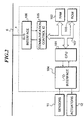
- Fig. 2 shows the arrangement of the ENG control ECU 1 which comprises a central processing unit (hereinafter referred to as "the CPU") 101, an input/output interface 104 connecting a plurality of sensors 11, and a plurality of actuators, such as fuel injection valves, to the CPU 101.
- the CPU 101 is connected via a bus line 107 to a RAM (Random Access Memory) 102, a ROM (Read Only Memory) 103, and a communication control IC (Integrated Circuit) 105.
- the communication control IC 105 is connected via a bus interface 106 to the network bus 6.
- the CPU 101 determines control parameters based on output signals from the sensors 11 according to a program stored in the ROM 103 for driving the actuators 12.
- the RAM 102 temporarily stores data of results of computation.
- the communication control IC controls transmission of a message to the network bus and reception of a message from the network bus.
- Fig. 3 shows details of the bus interface 106 connected to the communication control IC 105, and the network bus 6 comprised of twisted pair lines 6b and 6c connected at both ends of thereof to each other via respective terminal resistances 6a, 6a.
- the communication control IC 105 has a first sending terminal connected to a base of a transistor 119 via a resistance 115.
- the transistor 119 has an emitter thereof connected to a power supply line VSUP and a collector thereof connected via a resistance 116 to an inverting input terminal of a comparator 111 and to one 6b of the twisted pair lines 6b and 6c.
- the communication control IC 105 has a second sending terminal connected to a base of a transistor 120 via a resistance 117.
- the transistor 120 has an emitter thereof grounded and a collector thereof connected via a resistance 118 to a non-inverting input terminal of the comparator 111 and to one 6c of the twisted pair lines 6b and 6c.
- the non-inverting input terminal of the comparator 111 is connected via a resistance 112 to the power supply line VSUP, and also via a resistance 113 to the inverting input terminal of the comparator 111.
- the comparator 111 has its inverting input terminal grounded via a resistance 114, and delivers an output signal therefrom to a receiving terminal of the communication control IC 105.
- the resistances 116 and 118 are each set to approximately 30 ⁇ , the resistances 112 and 114 to approximately 2 k ⁇ , the resistance 113 to approximately 200 ⁇ , and the terminal resistances 6a to approximately 100 ⁇ .
- the first and second sending terminals of the communication control IC 106 are supplied with pulse signals reverse to each other in phase.
- both the transistors 119 and 120 are turned on to set the voltage of the one twisted pair line 6b at the high level and the other twisted pair line 6c at the low level.
- both the transistors 119 and 120 are turned off to set the voltage of the one twisted pair line 6b at the low level and the other twisted pair line 6c at the high level.
- a signal is sent out to the network bus 6.
- the ECU's 2 to 5 are basically constructed in the same manner. Therefore, even if one of the ECU's sends out a signal which sets the voltage of the one twisted pair line 6b at the low level (i.e. sets the voltage of the other twisted pair line 6c at the high level), when another ECU sends out a signal which sets the voltage of the one twisted pair line 6b at the high level, the state of the voltage of the twisted pair line 6b is set to the high level. Therefore, in the present embodiment, a state in which the one twisted pair line line 6b is at the high level (the other twisted pair line 6c is at the low level) is defined as a dominant state, and an opposite state thereof as a recessive state.
- a token passing method is employed. This takes into consideration the fact that compared with a CSMA/CD (Carrier Sense Multiple Access with Collision Detection) method which is capable settling the collision, the token passing method is advantageous in respect of an electric delay on the network bus, and is capable of easily determining the maximum message delay time period, allowing the network system to be be designed easily.
- CSMA/CD Carrier Sense Multiple Access with Collision Detection
- Fig. 4a and Fig. 4b show formats of messages used in data transmission in the present embodiment.
- Fig. 4a shows a format of a data message (second message) for sending a token (representative of the transmission right) and data
- Fig. 4b shows that of a token message (first message) for sending the token alone.
- the ECU's constituting the network system will be referred to as the nodes 1 to 5.
- a field F1 notifies the start of a message, which is formed by one dominant bit. This field is used for synchronization of all the nodes constituting the network system.
- a field F2 designates an address of a destination node to which the token is to be transferred, which is formed by four bits of data.
- the node address is set e.g. to one of values 0 to 4 in a manner corresponding to the ECU's 1 to 5.
- a field F3 designates a kind of message (token message or data message).
- a field F4 is a data unit comprised of a DN (Destination Node) field designating a node or nodes which should receive data contained in a DATA field, a DLC (Data Length) filed designating the length of a byte of the DATA field, an ID (Identifier) filed forming an identifier of the data, and the DATA filed containing information to be transmitted.
- DN Disination Node
- DLC Data Length
- ID Identifier
- the length of the DATA field is variable as can be presumed from the above description, and the total length of the data unit is variable within the range of 32 to 96 bytes.
- a delimitter (dividing character) having one recessive bit is interposed between the field F5 and the field F6.
- a field F6 is a second response field into which a data-acknowledging response (second acknowledge character) should be written by a node having normally or safely received the data, which is formed by an acknowledge slot having two bits.
- a sending node sends a message having the acknowledge slot as recessive bits, and the node or nodes which is/are designated in the message as one or ones to receive the information and has/have normally or safely received the data make(s) the data-acknowledging response by overwriting two dominant bits therein.
- a delimitter having two recessive bits is interposed between the fields F6 and F7.
- a field F7 is a first response field into which a token-acknowledging response (first acknowledge character) should be written by a node having normally or safely received the token, which is formed by an acknowledge slot having two bits, similarly to the field F6.
- the sending node sends a message having the acknowledge slot as recessive bits, and the node having received the token makes the token-acknowledging response by overwriting two dominant bits therein.
- a delimitter formed by two recessive bits is interposed between the filed F7 and the field F8.
- a field F8 designates the end of the message, and is formed by six recessive bits.
- the field F7 and the field F6 are provided as fields into which acknowledgement of the token and acknowledgement of data are made, respectively, which makes it possible for a sending end to promptly confirm whether or not the transfer of the token and the transmission of data have been successfully carried out.
- the token message shown in Fig. 4b is constructed such that the fields F4 to F6 are deleted from the data message, and a delimitter is interposed between the fields F3 and F7.
- a node to which the token is to be transferred is a node designated in the field F2 (TA).
- the token address is normally set by adding a value of one to the address of the sending node itself, and a message continues to be sent out until a token-acknowledging response is detected, by sequentially increasing the token address by an incremental value of 1. However, when a calculated value of the token address reaches a value of 16, the token address is set to 0, thus circulating token address through values of of 0 to 15.
- the node corresponding to the token address set in the message When the node corresponding to the token address set in the message has received the token, it overwrites two dominant bits into the acknowledge slot of the field F7 (TACK), thereby making the token-acknowledging response. When the token-acknowledging response is thus overwritten and the message normally terminates in the field F8 (EOM), the sending node having sent the token completes the transfer of the token, and the receiving node has acquired the token.
- TACK acknowledge slot of the field F7
- EOM the message normally terminates in the field F8
- the transmission error is detected by monitoring of data, detection by CRC, detection of bit stuff error, and a message format check.
- a transmission error is detected when data a sending node is transmitting does not coincide with data loaded on the bus.
- this monitoring of data is inhibited with the acknowledge slots of the fields F6 and F7, and one recessive bit subsequent thereto.
- a transmission error is detected when an error is found as to CRC characters set in the field F5 (FCS) and this detection is performed by nodes other than the sending node.
- bit stuff error detection it is determined that there is an error in transmission when more than 5 consecutive bits designate the same logical state, and this detection is performed by nodes other than the sending node.
- the fields F6 (DACK), F7 (TACK), F8 (EOM) and the delimitters are executed from objects of monitoring.
- an error is detected when an illegal logical state is found in the fields of the fixed-logical-state bits (the fields F3, F8 and the delimitters), and this type of error detection is performed by nodes other than the sending node.
- a node having detected the error immediately sends out an error message (six consecutive dominant bits), whereby even if a transmission error is detected by a node or nodes other than the sending node, the sending node can recognize the transmission error.
- the communication control IC 105 of each of the ECU's 1 to 5 determines at a step S1 of Fig. 5 whether or not the network bus is idling, to determinate whether the data transmission system is in a state in which the token has not been generated immediately after the start of system, or has been lost due to failure of a node having received the token. If the answer to this question is negative (NO), i.e. if another ECU is sending a message, the present program is immediately terminated.
- NO negative
- the present ECU starts data transmission via the communication control IC 105 and the bus interface 106 at a step S2, assuming that the present node has acquired the token. Then, data sent from the present node is compared with data on the network bus 6 bit by bit to determine whether both the data are identical to each other at a step S3. If the answer to this question is affirmative (YES), i.e.
- the present program proceeds to a step S4, where it is determined whether or not transmission of the whole sequence of data has been completed. If the answer to this question is negative (NO), the program returns to the step S3, where data subsequently sent out is compared with data loaded on the network bus, in the same manner as described above.
- the present node is found to be defeated in contention for acquiring the token to stop data transmission when the above-described procedure is carried out.
- the above-mentioned method of the error detection by monitoring data is utilized for determining that the data sent out and the data loaded on the system bus do not coincide with each other.
- the coincidence of the data is determined by calculating an exclusive OR of the data sent out and the data received from the network bus 6.
- the data sent out from the present node is different from the data loaded on the network bus 6, it means that there has been a contention for the token with other nodes, and the present node has been defeated in the contention, so that the data transmission is stopped at a step S5, followed by terminating the present program.
- step S6 determines whether or not the transfer of the token has been completed, by making a check for the token-acknowledging response. If the transfer of the token has not been completed, a value of 1 is added to the token address of the token message, and then the resulting token message is sent out to the network bus 6 at a step S7. The steps S6 and S7 are repeatedly carried out until the transfer of the token is completed, whereupon the present program is terminated.
- bits corresponding to the bit numbers 1 to 4 shown in Fig. 6a are in the same logical states, respectively, and the logical states of the data sent from Node 1 and Node 2, and the logical state of the network bus are all equal to each other. Accordingly, Node 1 and Node 2 both continue to send out respective messages from bit No. 1 to bit No. 4.
- Fig. 6a to Fig. 6d show a case where two nodes are in contention for the token.
- a contention for the token arises among more than two nodes.
- a token is generated or initially given to one of the nodes by contention for the token as described above, and then the token is circulated through or transferred round the nodes. This makes it possible to promptly generate the token by giving a chance of acquiring the token equally to all the nodes, enabling the system to function efficiently.
- the present invention is not limited to the above embodiment, but as a manner of mediation of contention, the logical state "0" may be used for a dominant bit and the logical state "1" for a recessive bit, inversely to the above embodiment.
- a node to which the token is first transferred is not necessarily restricted to a node having a node address following the address having initially acquired the token, but the token may be first transferred to a predetermined node having the smallest node address, then permitting the node to circulate through the nodes in a predetermined cycle.
- the first acknowledge character to be overwritten into the field F7 is referred to as "the token ACK”, while the second acknowledge character to be overwritten in the field F6 as "the data ACK”.
Claims (4)
- Système de transmission de données pour un véhicule, comportant une pluralité de systèmes de commande (1, 2, 3, 4, 5) installés sur ledit véhicule, un bus réseau (6) connectant ladite pluralité de systèmes de commande les uns aux autres pour faire circuler un droit de transmission à travers ladite pluralité de systèmes de commande de manière à effectuer une transmission d'un message entre ladite pluralité de systèmes de commande, et des moyens d'émetteur-récepteur pour transmettre des données vers le reste de ladite pluralité de systèmes de commande, ou recevoir des données depuis ceux-ci, via ledit bus réseau,
caractérisé en ce que chaque système de ladite pluralité de systèmes de commande comporte :des moyens de détection de collision pour détecter une collision entre des données transmises par lesdits moyens d'émetteur-récepteur et des données transmises depuis un quelconque système parmi le reste de ladite pluralité de systèmes de commande,des moyens de médiation pour effectuer une médiation sur lesdites données transmises par lesdits moyens d'émetteur-récepteur et ayant été détectées comme étant entrées en collision avec lesdites données transmises par un quelconque système parmi le reste de ladite pluralité de systèmes de commande pour amener lesdits moyens d'émetteur-récepteur à poursuivre une transmission de données ou à stopper ladite transmission de données, dans le but d'éviter ladite collision,des moyens de surveillance pour surveiller ledit droit de transmission, etdes moyens de commande pour amener lesdits moyens d'émetteur-récepteur à commencer une transmission de données lorsque lesdits moyens de surveillance détectent que ledit droit de transmission n'est pas généré ou perdu par ledit système, et amener lesdits moyens d'émetteur-récepteur à poursuivre la transmission desdites données lorsque lesdits moyens de détection de collision ne détectent pas une collision desdites données avec des données transmises par le reste de ladite pluralité de systèmes de commande, ou lorsque lesdits moyens de médiation amènent ledit émetteur-récepteur à poursuivre une transmission de données. - Système de transmission de données selon la revendication 1, comportant de plus des moyens de transfert pour transférer ledit droit de transmission à un système de commande ultérieur d'une manière prédéterminée, lorsque lesdits moyens de commande amènent lesdits moyens d'émetteur-récepteur à poursuivre ladite transmission de données jusqu'à ce que ladite transmission de données soit achevée.
- Système de transmission de données selon la revendication 1 ou 2, dans lequel lesdits moyens de médiation sont adaptés pour comparer lesdites données transmises par lesdits moyens d'émetteur-récepteur et lesdites données reçues via ledit bus réseau depuis le reste de ladite pluralité de systèmes de commande, bit par bit, sur la base de la logique considérant un des niveaux logiques de données de transmission en tant que dominant, et l'autre niveau desdits niveaux logiques desdites données de transmission en tant que récessif, et sont adaptés pour amener lesdits moyens d'émetteur-récepteur à stopper ladite transmission de données lorsque lesdites données transmises par lesdits moyens d'émetteur-récepteur et lesdites données reçues depuis ledit bus réseau sont différentes les unes des autres.
- Système de transmission de données selon la revendication 2 ou 3, dans lequel lesdits moyens de transfert sont adaptés pour transférer ledit droit de transmission à ladite unité de commande ultérieure en augmentant d'un nombre prédéterminé une adresse représentative de chaque système de ladite pluralité de systèmes de commande incorporant lesdits moyens de transfert.
Priority Applications (3)
| Application Number | Priority Date | Filing Date | Title |
|---|---|---|---|
| EP00105838A EP1022877B1 (fr) | 1993-02-15 | 1994-02-15 | Procédé de transmission de données |
| EP00105839A EP1022878B1 (fr) | 1993-02-15 | 1994-02-15 | Dispositif de transmission de données |
| EP00105840A EP1022879B1 (fr) | 1993-02-15 | 1994-02-15 | Dispositif de transmission de données |
Applications Claiming Priority (12)
| Application Number | Priority Date | Filing Date | Title |
|---|---|---|---|
| JP48559/93 | 1993-02-15 | ||
| JP5048559A JP2857655B2 (ja) | 1993-02-15 | 1993-02-15 | 車両用データ伝送システム |
| JP5048560A JP2947437B2 (ja) | 1993-02-15 | 1993-02-15 | データ伝送方法 |
| JP4856093 | 1993-02-15 | ||
| JP48560/93 | 1993-02-15 | ||
| JP4855993 | 1993-02-15 | ||
| JP5080216A JP2784709B2 (ja) | 1993-03-15 | 1993-03-15 | 車両用データ伝送システム |
| JP8021693 | 1993-03-15 | ||
| JP80216/93 | 1993-03-15 | ||
| JP5084079A JP2947496B2 (ja) | 1993-03-18 | 1993-03-18 | 車両用データ伝送システム |
| JP8407993 | 1993-03-18 | ||
| JP84079/93 | 1993-03-18 |
Related Child Applications (3)
| Application Number | Title | Priority Date | Filing Date |
|---|---|---|---|
| EP00105839A Division EP1022878B1 (fr) | 1993-02-15 | 1994-02-15 | Dispositif de transmission de données |
| EP00105840A Division EP1022879B1 (fr) | 1993-02-15 | 1994-02-15 | Dispositif de transmission de données |
| EP00105838A Division EP1022877B1 (fr) | 1993-02-15 | 1994-02-15 | Procédé de transmission de données |
Publications (3)
| Publication Number | Publication Date |
|---|---|
| EP0612169A2 EP0612169A2 (fr) | 1994-08-24 |
| EP0612169A3 EP0612169A3 (en) | 1995-10-11 |
| EP0612169B1 true EP0612169B1 (fr) | 2001-11-07 |
Family
ID=27462227
Family Applications (4)
| Application Number | Title | Priority Date | Filing Date |
|---|---|---|---|
| EP00105839A Expired - Lifetime EP1022878B1 (fr) | 1993-02-15 | 1994-02-15 | Dispositif de transmission de données |
| EP00105840A Expired - Lifetime EP1022879B1 (fr) | 1993-02-15 | 1994-02-15 | Dispositif de transmission de données |
| EP94102290A Expired - Lifetime EP0612169B1 (fr) | 1993-02-15 | 1994-02-15 | Procédé et dispositif de transmission de données |
| EP00105838A Expired - Lifetime EP1022877B1 (fr) | 1993-02-15 | 1994-02-15 | Procédé de transmission de données |
Family Applications Before (2)
| Application Number | Title | Priority Date | Filing Date |
|---|---|---|---|
| EP00105839A Expired - Lifetime EP1022878B1 (fr) | 1993-02-15 | 1994-02-15 | Dispositif de transmission de données |
| EP00105840A Expired - Lifetime EP1022879B1 (fr) | 1993-02-15 | 1994-02-15 | Dispositif de transmission de données |
Family Applications After (1)
| Application Number | Title | Priority Date | Filing Date |
|---|---|---|---|
| EP00105838A Expired - Lifetime EP1022877B1 (fr) | 1993-02-15 | 1994-02-15 | Procédé de transmission de données |
Country Status (4)
| Country | Link |
|---|---|
| US (4) | US5696904A (fr) |
| EP (4) | EP1022878B1 (fr) |
| CA (1) | CA2115730C (fr) |
| DE (4) | DE69428930T2 (fr) |
Cited By (1)
| Publication number | Priority date | Publication date | Assignee | Title |
|---|---|---|---|---|
| CN114531314A (zh) * | 2022-01-11 | 2022-05-24 | 宁波天擎航天科技有限公司 | 航天领域大数据可靠传输的方法、电子设备及存储介质 |
Families Citing this family (54)
| Publication number | Priority date | Publication date | Assignee | Title |
|---|---|---|---|---|
| EP1022878B1 (fr) * | 1993-02-15 | 2004-06-30 | Honda Giken Kogyo Kabushiki Kaisha | Dispositif de transmission de données |
| JP2765538B2 (ja) * | 1995-11-30 | 1998-06-18 | 日本電気株式会社 | データ転送制御装置 |
| GB9603582D0 (en) | 1996-02-20 | 1996-04-17 | Hewlett Packard Co | Method of accessing service resource items that are for use in a telecommunications system |
| GB9605048D0 (en) * | 1996-03-09 | 1996-05-08 | Jaguar Cars | Multiplexed electronic control systems |
| US5822543A (en) * | 1996-07-08 | 1998-10-13 | International Business Machines Corporation | Gathering data handling statistics in non-synchronous data communication networks |
| JP3117000B2 (ja) * | 1997-02-21 | 2000-12-11 | 株式会社デンソー | 通信システムおよびそれに使用される電子制御装置 |
| US5931915A (en) | 1997-05-13 | 1999-08-03 | International Business Machines Corporation | Method for processing early arrival messages within a multinode asynchronous data communications system |
| US6038689A (en) * | 1997-08-21 | 2000-03-14 | Digital Equipment Corporation | Fault notification system and process using local area network |
| ES2147119B1 (es) * | 1998-03-10 | 2001-03-16 | Mecanismos Aux Es Ind S L | Sistema para transferir informacion binaria. |
| DE19843810A1 (de) * | 1998-09-24 | 2000-03-30 | Philips Corp Intellectual Pty | Datenbus |
| JP2000156685A (ja) | 1998-11-18 | 2000-06-06 | Fuji Heavy Ind Ltd | 車両制御システムの異常監視装置 |
| US6389550B1 (en) * | 1998-12-23 | 2002-05-14 | Ncr Corporation | High availability protocol computing and method |
| US6604038B1 (en) * | 1999-11-09 | 2003-08-05 | Power Talk, Inc. | Apparatus, method, and computer program product for establishing a remote data link with a vehicle with minimal data transmission delay |
| MXPA02004971A (es) * | 1999-11-17 | 2002-09-18 | Vehicle Enhancement Sys Inc | Metodo para comunicacion de datos entre un vehiculo y una terminal remota. |
| US6661998B1 (en) * | 1999-12-23 | 2003-12-09 | Denso Corporation | Mobile station to base station communication and signal acknowledgement |
| US6484082B1 (en) * | 2000-05-24 | 2002-11-19 | General Motors Corporation | In-vehicle network management using virtual networks |
| DE10027017A1 (de) * | 2000-05-31 | 2002-02-28 | Bayerische Motoren Werke Ag | Betriebsverfahren für einen Datenbus für mehrere Teilnehmer |
| US6775690B1 (en) * | 2000-07-21 | 2004-08-10 | At&T Corp. | Time-dependent messaging |
| EP1202146A1 (fr) * | 2000-10-23 | 2002-05-02 | Lucent Technologies Inc. | Système de commande de paramètres électriques de composants de circuits |
| IES20010064A2 (en) * | 2001-01-29 | 2002-04-17 | Eland Technologies Inc | Computer network system |
| US7164654B2 (en) * | 2001-03-09 | 2007-01-16 | Denso Corporation | ARQ parameter retransmission control for variable data rate channels |
| US6973492B2 (en) * | 2001-09-07 | 2005-12-06 | International Business Machines Corporation | Method and apparatus for collecting page load abandons in click stream data |
| DE50211756D1 (de) * | 2002-02-22 | 2008-04-03 | Bosch Gmbh Robert | Verfahren und vorrichtung zur übermittlung von messdaten über einen can-bus in einem objekterfassungssystem für kraftfahrzeuge |
| JP4100108B2 (ja) * | 2002-09-12 | 2008-06-11 | 株式会社デンソー | 制御システム |
| WO2004084505A1 (fr) * | 2003-03-18 | 2004-09-30 | Fujitsu Limited | Dispositif d'attribution de bande de transmission |
| FR2852765B1 (fr) * | 2003-03-21 | 2005-06-24 | Peugeot Citroen Automobiles Sa | Systeme de securisation de la transmission d'au moins certaines trames de commande sur un reseau multiplexe de transmission d'informations |
| US7461319B2 (en) * | 2003-04-04 | 2008-12-02 | Sun Microsystems, Inc. | System and method for downloading files over a network with real time verification |
| US7983820B2 (en) | 2003-07-02 | 2011-07-19 | Caterpillar Inc. | Systems and methods for providing proxy control functions in a work machine |
| US7516244B2 (en) * | 2003-07-02 | 2009-04-07 | Caterpillar Inc. | Systems and methods for providing server operations in a work machine |
| US7532640B2 (en) | 2003-07-02 | 2009-05-12 | Caterpillar Inc. | Systems and methods for performing protocol conversions in a machine |
| US7162339B2 (en) * | 2004-08-31 | 2007-01-09 | General Motors Corporation | automated vehicle calibration and testing system via telematics |
| DE102004050424B4 (de) * | 2004-10-15 | 2010-04-15 | Bosch Rexroth Ag | Verfahren zur Übertragung von Daten in einem Kommunikationssystem |
| ATE436133T1 (de) * | 2004-11-29 | 2009-07-15 | Scania Cv Abp | Verfahren zur start-up-kontrolle von netzkommunikation in einem kommunikationsnetz |
| JP4437468B2 (ja) | 2004-12-06 | 2010-03-24 | 富士通テン株式会社 | 車両用電子制御装置 |
| JP2006309547A (ja) * | 2005-04-28 | 2006-11-09 | Toshiba Corp | 情報処理装置及び情報処理方法 |
| GB2431769B (en) * | 2005-10-25 | 2009-06-10 | Laurence Wrenn | Switching unit |
| EP1943781A1 (fr) | 2005-11-03 | 2008-07-16 | Continental Teves AG & Co. oHG | Circuit de commutation de signal mixte destine a un systeme de commande ou de regulation electronique securise |
| JP4681504B2 (ja) * | 2006-05-22 | 2011-05-11 | ヤマハ発動機株式会社 | リモコン用電子制御装置及びそれを用いた遠隔操作システム |
| US20080082708A1 (en) * | 2006-09-29 | 2008-04-03 | Kar Leong Wong | Token hold off for chipset communication |
| KR101114609B1 (ko) | 2007-10-03 | 2012-03-05 | 후지쯔 가부시끼가이샤 | 무선 통신 장치, 무선 통신 제어 장치, 무선 통신 방법, 무선 통신 프로그램 기억 매체, 무선 통신 제어 방법, 및 무선 통신 제어 프로그램 기억 매체 |
| FR2926943B1 (fr) * | 2008-01-30 | 2012-01-13 | Canon Kk | Procedes de transmission et reconstruction de sequences d'unites de donnees, produit programme d'ordinateur, moyen de stockage, noeuds emetteur et recepteur correspondants |
| DE102008012730B3 (de) * | 2008-03-05 | 2009-08-27 | Robert Bosch Gmbh | Elektronische Steuer- und Diagnoseeinrichtung zum Betreiben einer Ventileinheit |
| US8238538B2 (en) | 2009-05-28 | 2012-08-07 | Comcast Cable Communications, Llc | Stateful home phone service |
| EP2355393B1 (fr) * | 2010-01-21 | 2013-12-11 | Rohde & Schwarz GmbH & Co. KG | Procédé et appareil pour déterminer un nombre optimisé de transmissions pour un paquet de données dans un système de transmission multidiffusion |
| WO2012004836A1 (fr) * | 2010-07-08 | 2012-01-12 | 三菱電機株式会社 | Dispositif de détermination d'anomalies dans les données d'un véhicule |
| JP5651442B2 (ja) * | 2010-11-29 | 2015-01-14 | 矢崎総業株式会社 | 動作支援装置、電子機器、電子制御装置、及び、制御システム |
| DE102011116642A1 (de) * | 2011-10-20 | 2013-04-25 | Audi Ag | Übertragungseinrichtung und Verfahren zur sicheren Übertragung eines Sensorsignals an ein Übertragungsziel und Kraftfahrzeug |
| US9665080B2 (en) | 2012-03-21 | 2017-05-30 | Husqvarna Ab | Method for communicating data between a control system of a power tool and a computing device |
| EP2892199B1 (fr) | 2014-01-06 | 2018-08-22 | Argus Cyber Security Ltd. | Système de sécurité automobile global |
| WO2016201091A1 (fr) * | 2015-06-10 | 2016-12-15 | RunSafe Security, Inc. | Système et procédé de surveillance d'un réseau can |
| US10423475B2 (en) * | 2016-09-30 | 2019-09-24 | Microsoft Technology Licensing, Llc | Stateful tokens for communicating with external services |
| CN106628070B (zh) * | 2016-11-09 | 2018-06-26 | 重庆长安工业(集团)有限责任公司 | 基于船用D30mm系统操控台的控制方法 |
| EP3506584B1 (fr) * | 2017-12-28 | 2020-12-23 | Vestel Elektronik Sanayi ve Ticaret A.S. | Procédé et appareil pour une communication entre une pluralité de cartes de commande |
| CN110213018B (zh) * | 2019-05-09 | 2022-07-15 | 北京汽车股份有限公司 | 车载总线的数据通信方法、装置及车辆 |
Family Cites Families (23)
| Publication number | Priority date | Publication date | Assignee | Title |
|---|---|---|---|---|
| US4560985B1 (en) * | 1982-05-07 | 1994-04-12 | Digital Equipment Corp | Dual-count, round-robin ditributed arbitration technique for serial buses |
| US4590468A (en) * | 1983-03-10 | 1986-05-20 | Western Digital Corporation | Token access controller protocol and architecture |
| JPS59211143A (ja) * | 1983-05-17 | 1984-11-29 | Nissan Motor Co Ltd | マイクロコンピユ−タを用いた車両用制御回路 |
| US4556974A (en) * | 1983-10-07 | 1985-12-03 | Honeywell Inc. | Method for passing a token in a local-area network |
| US4551721A (en) * | 1983-10-07 | 1985-11-05 | Honeywell Inc. | Method for initializing a token-passing local-area network |
| US4725834A (en) * | 1984-02-27 | 1988-02-16 | American Telephone And Telegraph Company, At&T Bell Laboratories | Reliable broadcast protocol for a token passing bus network |
| US4715031A (en) * | 1985-09-23 | 1987-12-22 | Ford Motor Company | Vehicular data transfer communication system |
| DE3534216A1 (de) * | 1985-09-25 | 1987-04-02 | Bayerische Motoren Werke Ag | Datenbussystem fuer fahrzeuge |
| JPS62151903A (ja) * | 1985-12-25 | 1987-07-06 | Nippon Denso Co Ltd | 車両に搭載される電子制御装置 |
| JPS62159539A (ja) * | 1986-01-07 | 1987-07-15 | Nec Corp | デ−タ伝送装置 |
| US4860006A (en) * | 1986-06-05 | 1989-08-22 | Michael Barall | Heartbeat collision avoidance method and circuit |
| US4766530A (en) * | 1986-11-24 | 1988-08-23 | Westinghouse Electric Corp. | Token passing scheme for a predetermined configuration local area network |
| JPS6457856A (en) * | 1987-02-23 | 1989-03-06 | Nitsuko Ltd | Automatic incoming circuit in telephone set |
| JPH0771088B2 (ja) * | 1987-04-06 | 1995-07-31 | 古河電気工業株式会社 | 多重伝送方式 |
| JPS6458756A (en) * | 1987-08-27 | 1989-03-06 | Inax Corp | Method of executing tile |
| JPS6458900A (en) * | 1987-08-28 | 1989-03-06 | Shimizu Construction Co Ltd | Piping reclamation shutoff valve |
| JPH06101732B2 (ja) * | 1987-11-30 | 1994-12-12 | 三菱電機株式会社 | 通信制御方式 |
| US4899143A (en) * | 1988-04-21 | 1990-02-06 | Bell Communications Research, Inc. | High capacity communication system over collision-type channels |
| JPH0769376B2 (ja) * | 1989-08-30 | 1995-07-31 | マツダ株式会社 | 車両用多重伝送装置 |
| JP2770282B2 (ja) * | 1992-04-13 | 1998-06-25 | 本田技研工業株式会社 | 車両用データ伝送システム |
| EP0580938B1 (fr) * | 1992-06-26 | 2001-09-26 | Yokogawa Electric Corporation | Dispositif de commande pour la communication duplex |
| US5351241A (en) * | 1992-12-24 | 1994-09-27 | Intel Corporation | Twisted pair ethernet hub for a star local area network |
| EP1022878B1 (fr) * | 1993-02-15 | 2004-06-30 | Honda Giken Kogyo Kabushiki Kaisha | Dispositif de transmission de données |
-
1994
- 1994-02-15 EP EP00105839A patent/EP1022878B1/fr not_active Expired - Lifetime
- 1994-02-15 DE DE69428930T patent/DE69428930T2/de not_active Expired - Fee Related
- 1994-02-15 EP EP00105840A patent/EP1022879B1/fr not_active Expired - Lifetime
- 1994-02-15 DE DE69433866T patent/DE69433866T2/de not_active Expired - Fee Related
- 1994-02-15 EP EP94102290A patent/EP0612169B1/fr not_active Expired - Lifetime
- 1994-02-15 DE DE69433882T patent/DE69433882T2/de not_active Expired - Fee Related
- 1994-02-15 DE DE69433098T patent/DE69433098T2/de not_active Expired - Fee Related
- 1994-02-15 EP EP00105838A patent/EP1022877B1/fr not_active Expired - Lifetime
- 1994-02-15 CA CA002115730A patent/CA2115730C/fr not_active Expired - Fee Related
-
1995
- 1995-05-31 US US08/454,752 patent/US5696904A/en not_active Expired - Fee Related
- 1995-05-31 US US08/455,247 patent/US5586118A/en not_active Expired - Fee Related
- 1995-05-31 US US08/455,512 patent/US5764919A/en not_active Expired - Fee Related
- 1995-09-14 US US08/527,953 patent/US5659702A/en not_active Expired - Fee Related
Cited By (2)
| Publication number | Priority date | Publication date | Assignee | Title |
|---|---|---|---|---|
| CN114531314A (zh) * | 2022-01-11 | 2022-05-24 | 宁波天擎航天科技有限公司 | 航天领域大数据可靠传输的方法、电子设备及存储介质 |
| CN114531314B (zh) * | 2022-01-11 | 2023-12-22 | 宁波天擎航天科技有限公司 | 航天领域大数据可靠传输的方法、电子设备及存储介质 |
Also Published As
| Publication number | Publication date |
|---|---|
| EP0612169A3 (en) | 1995-10-11 |
| EP1022878B1 (fr) | 2004-06-30 |
| EP1022878A1 (fr) | 2000-07-26 |
| EP1022879B1 (fr) | 2003-08-27 |
| US5764919A (en) | 1998-06-09 |
| US5586118A (en) | 1996-12-17 |
| DE69428930D1 (de) | 2001-12-13 |
| DE69428930T2 (de) | 2002-06-27 |
| DE69433098T2 (de) | 2004-03-25 |
| US5696904A (en) | 1997-12-09 |
| DE69433882D1 (de) | 2004-08-05 |
| CA2115730A1 (fr) | 1994-08-16 |
| CA2115730C (fr) | 1999-05-04 |
| DE69433866D1 (de) | 2004-07-29 |
| DE69433098D1 (de) | 2003-10-02 |
| DE69433866T2 (de) | 2005-06-30 |
| US5659702A (en) | 1997-08-19 |
| DE69433882T2 (de) | 2005-08-25 |
| EP1022877B1 (fr) | 2004-06-23 |
| EP1022877A1 (fr) | 2000-07-26 |
| EP1022879A1 (fr) | 2000-07-26 |
| EP0612169A2 (fr) | 1994-08-24 |
Similar Documents
| Publication | Publication Date | Title |
|---|---|---|
| EP0612169B1 (fr) | Procédé et dispositif de transmission de données | |
| US5499247A (en) | Multiplex transmission system having plurality of nodes and common transmission line and using divided data areas | |
| US5357525A (en) | Multiplex transmission system | |
| EP0449304B1 (fr) | Système de transmission multiplexé pour être utilisé dans des véhicules | |
| KR100362236B1 (ko) | 다중데이타통신시스템 | |
| US5585788A (en) | Data transmission system for automotive vehicles | |
| JP2873514B2 (ja) | 多重伝送方法 | |
| US5982781A (en) | Process for information transmission in a bus system having several participants | |
| EP0539096A1 (fr) | Procédé de transmission multiplexé et procédé de synchronisation dans une transmission multiplexée | |
| JP2995348B2 (ja) | 多重伝送方法 | |
| CA2226421C (fr) | Methode et systeme de transmission de donnees | |
| CA2363980C (fr) | Methode et systeme de transmission de donnees | |
| JP2781397B2 (ja) | 多重伝送装置 | |
| JP2857655B2 (ja) | 車両用データ伝送システム | |
| JP2775659B2 (ja) | データ伝送方法 | |
| JP2770281B2 (ja) | データ伝送方法 | |
| JP2784709B2 (ja) | 車両用データ伝送システム | |
| JP2947437B2 (ja) | データ伝送方法 | |
| JP2947496B2 (ja) | 車両用データ伝送システム | |
| EP0615366A1 (fr) | Procédé et système d'accès à un support de communication pour la transmission asynchrone | |
| JPH10136465A (ja) | 車両データ伝送システム | |
| JPH1051474A (ja) | 車両データ伝送システム | |
| JPH10187598A (ja) | 車両データ伝送システム | |
| JPH11112536A (ja) | 車両多重通信装置 | |
| JPH05191415A (ja) | 多重通信方式 |
Legal Events
| Date | Code | Title | Description |
|---|---|---|---|
| PUAI | Public reference made under article 153(3) epc to a published international application that has entered the european phase |
Free format text: ORIGINAL CODE: 0009012 |
|
| AK | Designated contracting states |
Kind code of ref document: A2 Designated state(s): DE FR GB |
|
| PUAL | Search report despatched |
Free format text: ORIGINAL CODE: 0009013 |
|
| AK | Designated contracting states |
Kind code of ref document: A3 Designated state(s): DE FR GB |
|
| 17P | Request for examination filed |
Effective date: 19951014 |
|
| 17Q | First examination report despatched |
Effective date: 19990902 |
|
| GRAG | Despatch of communication of intention to grant |
Free format text: ORIGINAL CODE: EPIDOS AGRA |
|
| GRAG | Despatch of communication of intention to grant |
Free format text: ORIGINAL CODE: EPIDOS AGRA |
|
| GRAH | Despatch of communication of intention to grant a patent |
Free format text: ORIGINAL CODE: EPIDOS IGRA |
|
| GRAH | Despatch of communication of intention to grant a patent |
Free format text: ORIGINAL CODE: EPIDOS IGRA |
|
| GRAA | (expected) grant |
Free format text: ORIGINAL CODE: 0009210 |
|
| AK | Designated contracting states |
Kind code of ref document: B1 Designated state(s): DE FR GB |
|
| REF | Corresponds to: |
Ref document number: 69428930 Country of ref document: DE Date of ref document: 20011213 |
|
| REG | Reference to a national code |
Ref country code: GB Ref legal event code: IF02 |
|
| ET | Fr: translation filed | ||
| PGFP | Annual fee paid to national office [announced via postgrant information from national office to epo] |
Ref country code: FR Payment date: 20020607 Year of fee payment: 9 |
|
| PLBE | No opposition filed within time limit |
Free format text: ORIGINAL CODE: 0009261 |
|
| STAA | Information on the status of an ep patent application or granted ep patent |
Free format text: STATUS: NO OPPOSITION FILED WITHIN TIME LIMIT |
|
| 26N | No opposition filed | ||
| PGFP | Annual fee paid to national office [announced via postgrant information from national office to epo] |
Ref country code: GB Payment date: 20030212 Year of fee payment: 10 |
|
| PGFP | Annual fee paid to national office [announced via postgrant information from national office to epo] |
Ref country code: DE Payment date: 20030304 Year of fee payment: 10 |
|
| PG25 | Lapsed in a contracting state [announced via postgrant information from national office to epo] |
Ref country code: FR Free format text: LAPSE BECAUSE OF NON-PAYMENT OF DUE FEES Effective date: 20031031 |
|
| REG | Reference to a national code |
Ref country code: FR Ref legal event code: ST |
|
| PG25 | Lapsed in a contracting state [announced via postgrant information from national office to epo] |
Ref country code: GB Free format text: LAPSE BECAUSE OF NON-PAYMENT OF DUE FEES Effective date: 20040215 |
|
| PG25 | Lapsed in a contracting state [announced via postgrant information from national office to epo] |
Ref country code: DE Free format text: LAPSE BECAUSE OF NON-PAYMENT OF DUE FEES Effective date: 20040901 |
|
| GBPC | Gb: european patent ceased through non-payment of renewal fee |
Effective date: 20040215 |