EP0611700B1 - Récipient pour liquides - Google Patents
Récipient pour liquides Download PDFInfo
- Publication number
- EP0611700B1 EP0611700B1 EP94102504A EP94102504A EP0611700B1 EP 0611700 B1 EP0611700 B1 EP 0611700B1 EP 94102504 A EP94102504 A EP 94102504A EP 94102504 A EP94102504 A EP 94102504A EP 0611700 B1 EP0611700 B1 EP 0611700B1
- Authority
- EP
- European Patent Office
- Prior art keywords
- container
- portions
- annular
- axial direction
- annular convex
- Prior art date
- Legal status (The legal status is an assumption and is not a legal conclusion. Google has not performed a legal analysis and makes no representation as to the accuracy of the status listed.)
- Expired - Lifetime
Links
Images


Classifications
-
- B—PERFORMING OPERATIONS; TRANSPORTING
- B65—CONVEYING; PACKING; STORING; HANDLING THIN OR FILAMENTARY MATERIAL
- B65D—CONTAINERS FOR STORAGE OR TRANSPORT OF ARTICLES OR MATERIALS, e.g. BAGS, BARRELS, BOTTLES, BOXES, CANS, CARTONS, CRATES, DRUMS, JARS, TANKS, HOPPERS, FORWARDING CONTAINERS; ACCESSORIES, CLOSURES, OR FITTINGS THEREFOR; PACKAGING ELEMENTS; PACKAGES
- B65D1/00—Containers having bodies formed in one piece, e.g. by casting metallic material, by moulding plastics, by blowing vitreous material, by throwing ceramic material, by moulding pulped fibrous material, by deep-drawing operations performed on sheet material
- B65D1/02—Bottles or similar containers with necks or like restricted apertures, designed for pouring contents
- B65D1/0223—Bottles or similar containers with necks or like restricted apertures, designed for pouring contents characterised by shape
- B65D1/0292—Foldable bottles
-
- B—PERFORMING OPERATIONS; TRANSPORTING
- B29—WORKING OF PLASTICS; WORKING OF SUBSTANCES IN A PLASTIC STATE IN GENERAL
- B29C—SHAPING OR JOINING OF PLASTICS; SHAPING OF MATERIAL IN A PLASTIC STATE, NOT OTHERWISE PROVIDED FOR; AFTER-TREATMENT OF THE SHAPED PRODUCTS, e.g. REPAIRING
- B29C49/00—Blow-moulding, i.e. blowing a preform or parison to a desired shape within a mould; Apparatus therefor
- B29C49/42—Component parts, details or accessories; Auxiliary operations
- B29C49/4273—Auxiliary operations after the blow-moulding operation not otherwise provided for
- B29C49/4283—Deforming the finished article
-
- Y—GENERAL TAGGING OF NEW TECHNOLOGICAL DEVELOPMENTS; GENERAL TAGGING OF CROSS-SECTIONAL TECHNOLOGIES SPANNING OVER SEVERAL SECTIONS OF THE IPC; TECHNICAL SUBJECTS COVERED BY FORMER USPC CROSS-REFERENCE ART COLLECTIONS [XRACs] AND DIGESTS
- Y10—TECHNICAL SUBJECTS COVERED BY FORMER USPC
- Y10S—TECHNICAL SUBJECTS COVERED BY FORMER USPC CROSS-REFERENCE ART COLLECTIONS [XRACs] AND DIGESTS
- Y10S215/00—Bottles and jars
- Y10S215/90—Collapsible wall structure
Definitions
- the present invention relates to a container for a liquid, and more specifically, to a container for a liquid which is suitable for use as a container for a processing solution which is used in developing processing of a photosensitive material.
- Photosensitive material processing apparatuses such as automatic developing apparatuses have used rigid containers for liquids which are formed by blow molding or injection blow molding and by using a single-layer material such as high density polyethylene (HDPE), polyvinylchloride resin (PVC) or polyethylene terephthalate (PET) or a multi-layer material such as nylon/polyethylene (NY/PE).
- HDPE high density polyethylene
- PVC polyvinylchloride resin
- PET polyethylene terephthalate
- NY/PE multi-layer material
- these materials are used as they are suitable for the self-supportability of the container (i.e., the ability of the container to stand alone without external support) and because they are suitable for the filling of the container with liquid at a factory and for the pouring of the liquid into a processing tank, thereby facilitating use of the container.
- these materials are used because they guarantee the strength required by UN regulations (regulations for the transport of exported dangerous substances, i.e., legal regulations considering the drop strength at -18°C)
- blow-molded containers have been developed in which a bellows portion is provided at a trunk portion of the container so that the container can be collapsed by being pressed.
- the collapsed state can be maintained by tightly closing a cap when the container is collapsed. Therefore, the collection efficiency improves when the containers are collected with the caps fastened thereto.
- blow-molded containers have been reused as material for resin manufactured products.
- used containers When used containers are collected for reuse, it is usually necessary to separately collect the cap and the container, which are formed of different resin materials, but deterioration of the collection efficiency should be kept to a minimum.
- the inventors of the present invention have tried to manufacture various types of containers having bellows portions of various cross sectional configurations, and have found that it is difficult for a gradually-widening container, which has a bellows portion with a circular cross section and in which the diameter of the bellows portions gradually increases from top to bottom, to return to its original configuration.
- Such containers are also known from EP 287170 A2
- containers for photographic processing solutions In the case of containers for photographic processing solutions, a plurality of containers for processing solutions which are filled with the same type of processing solution are packed in a corrugated fiberboard box or the like, or containers for processing solutions which are filled with different types of processing solutions such as developing solution, fixing solution, bleaching solution and the like are packed in the same corrugated fiberboard box, and are shipped from the manufacturer and distributed.
- containers for processing solutions which are filled with different types of processing solutions such as developing solution, fixing solution, bleaching solution and the like are packed in the same corrugated fiberboard box, and are shipped from the manufacturer and distributed.
- a main object of the present invention is to provide a container for a liquid whose volume can easily be reduced, i.e., the necessary space can be reduced, after use thereof without adversely effecting the ease of use of the container for a liquid.
- Another object of the present invention is to provide a container for a liquid which does not easily return to its original configuration after the volume thereof has been reduced.
- yet another object of the present invention is to provide a container for a liquid for a photographic processing material in which collecting efficiency and packing efficiency can be improved when the container and a cap are collected separately.
- the container for a liquid of the present invention includes a flexible container main body having a bellows portion at at least an axial direction portion of said container main body, and a rigid opening portion formed integrally with said container main body so as to protrude from said container main body in an axial direction, said opening portion being opened and closed by a lid member which engages with said opening portion.
- the bellows portion is formed at at least a portion of the flexible container main body in the axial direction thereof, the container main body expands and contracts in accordance with an external force when the lid member has been removed. As a result, the volume can be easily reduced by contracting the bellows portion. Further, because the bellows portion automatically expands and contracts during pouring of the liquid, the liquid is poured smoothly.
- An outer tube may be attached to the outer periphery of the bellows portion of the container for a liquid of the present invention so that the self-supportability of the container main body can be ensured by the outer tube.
- the container main body itself may be self-supportable or not. It is preferable that the container main body is not self-supportable in so far as the volume thereof can be reduced easily.
- the bellows portion may be provided continuously to the border portion of the opening portion and the container main body. In this way, the volume can be reduced even further by contracting the entire bellows portion.
- said bellows portion may be formed of a plurality of annular convex portions and band-shaped annular connecting portions, said plurality of annular convex portions being disposed at predetermined intervals along the axial direction of said container main body and respectively having, at an intermediate portion thereof in the axial direction, an annular maximum protruding portion which protrudes a maximum amount from a central axis in a direction orthogonal to the axial direction, and said band-shaped annular connecting portions connecting said annular convex portions, which are adjacent, at minimum protruding portions which protrude a minimum amount in the direction orthogonal to the axial direction of both axial direction ends of said annular convex portions. Because the annular connecting portions are formed during blow molding so as to be thicker than the annular convex portions, the self-supportability and self-maintainability of the container for a liquid can be ensured, and the volume thereof can be easily reduced.
- portion having a radius of curvature subsequently called R portion
- R portion may be formed at each of said annular convex portions at one of one axial direction side of the annular maximum protruding portion and another axial direction side of the annular maximum protruding portion. Accordingly, compared with a case in which no R portions are formed, it is difficult for the container for a liquid to return to its original configuration after the volume thereof is reduced.
- the container for a liquid of the present invention it suffices to not provide the band-shaped annular connecting portions and to form the bellows portion from only a plurality of annular convex portions which are disposed at predetermined intervals along the axial direction of the container main body, and that the axial direction ends of the respective annular convex portions are connected to each other at portions nearest to the central axis.
- the thickness of the connecting portions nearest to the central axis is greater than the thickness of the portions which are furthest from the central axis. It is desirable that the ratio of these thicknesses is about 1.1 to 5.0.
- parison control may be used to adjust the thicknesses such that the thickness of the connecting portions nearest to the central axis is greater than the thickness of the portions which are furthest from the central axis.
- R portions be formed at each annular convex portion at the upper side and the lower side respectively of the maximum protruding portion which protrudes the furthest in the direction orthogonal to the axial direction, and that the respective radii of curvature of the R portions are different. Further, from the standpoint of improving the collapsing efficiency and the like, it is preferable to form concave grooves in each annular convex portion along the entire periphery of the upper side or the lower side of the maximum protruding portion which protrudes the most in the direction orthogonal to the axis.
- the bellows portion includes a plurality of annular convex portions whose cross sections orthogonal to the axis are substantially rectangular.
- the annular convex portions are disposed at predetermined intervals along the axial direction of the container main body and have, at intermediate portions thereof in the axial direction, annular maximum protruding portions which have the same size and the same configuration so as to be set in a superposed arrangement when viewed from the axial direction. Therefore, when a plurality of the containers for a photographic processing composition are packed in a box, there is almost no dead space between the containers. Accordingly, the efficiency of packing the shipped containers for a photographic processing composition can be improved for distribution.
- the axial direction dimension of either the opening portion side of the annular maximum protruding portion or the side of the annular maximum protruding portion opposite to the opening portion is larger than the axial direction dimension of the other of the opening portion side and the side opposite thereto. Therefore, by pushing the opening portion in the axial direction, the portion at the other side of the annular maximum protruding portion of the annular convex portion caves in toward the one side and enters into the inner side of the one side portion of the annular maximum protruding portion. Accordingly, the container main body is compressed and the volume thereof is reduced, and after the volume is reduced, it is difficult for the container main body to return to its original configuration. The requisite collecting efficiency for the containers for a photographic processing composition can thereby be improved.
- the container for a liquid 10 may be formed of a multi-layer structure with low density polyethylene as the main body, such as a three-layer structure of low density polyethylene / polyvinyl alcohol - ethylene copolymer / low density polyethylene (LDPE/EVOH/LDPE) or a two-layer structure of low density polyethylene / nylon (LDPE/NY) or the like.
- the gas barrier ability should be less than or equal to 25 ml/m 2 ⁇ day ⁇ atm (20°C 65%), and preferably 0.5 to 10 ml/m 2 ⁇ day ⁇ atm (20°C 65%).
- the container for a liquid 10 may be formed by using a low density polyethylene (LDPE) simple substance or ethylene - vinyl acetate copolymer resin (EVA; in this case, EVA with densities exceeding 0.940 g/cc can also be used).
- LDPE low density polyethylene
- EVA ethylene - vinyl acetate copolymer resin
- Low density polyethylenes having densities of less than or equal to 0.940 g/cc, preferably 0.90 g/cc to 0.940 g/cc, and more preferably 0.905 g/cc to 0.925 g/cc can be used.
- the gas barrier ability of the container for a liquid 10 in this case may be greater than or equal to 50 ml/m 2 ⁇ day ⁇ atm (20°C 65%), for example, 100 to 5000 ml/m 2 ⁇ day ⁇ atm (20°C 65%).
- the container for a liquid 10 is light-weight compared to conventional containers formed from high density polyethylene (HDPE).
- HDPE high density polyethylene
- a container for a photographic processing composition 110 of the present embodiment which is illustrated in Fig. 1, includes a flexible container main body 112 and a rigid opening portion 114 which protrudes upwardly from the container main body 112.
- the container main body 112 and the opening portion 114 are formed integrally by blow molding.
- the cross sectional configuration of the container for a photographic processing composition 110 is substantially rectangular (as can be seen in the plan view of Fig. 2).
- a bellows portion 116 is formed at the container main body 112 so as to be continuous from the boundary between the container main body 112 and the opening portion 114 to the bottom portion.
- the bellows portion 116 includes first, second, third, fourth and fifth annular convex portions 118, 120, 122, 124, 126, and first, second, third, and fourth annular connecting portions 128, 130, 132, 134.
- the first through the fifth annular convex portions 118, 120, 122, 124, 126 are disposed at predetermined intervals along the direction of the A-A axis.
- the first annular connecting portion 128 is band-shaped and connects the first annular convex portion 118 and the second annular convex portion 120 at respective minimum protruding portions, which protrude the least in a direction orthogonal to the axis, of both axial direction ends of the first annular convex portion 118 and the second annular convex portion 120 (the upper and lower ends in Fig. 1).
- the second annular connecting portion 130 is band-shaped and connects the second annular convex portion 120 and the third annular convex portion 122 at respective minimum protruding portions, which protrude the least in the direction orthogonal to the axis, of both axial direction ends of the second annular convex portion 120 and the third annular convex portion 122.
- the third annular connecting portion 132 connects the third annular convex portion 122 and the fourth annular convex portion 124 at respective minimum protruding portions, which protrude the least in the direction orthogonal to the axis, of both axial direction ends of the third annular convex portion 122 and the fourth annular convex portion 124.
- the fourth annular connecting portion 134 connects the fourth annular convex portion 124 and the fifth annular convex portion 126 at respective minimum protruding portions, which protrude the least in the direction orthogonal to the axis, of both axial direction ends of the fourth annular convex portion 124 and the fifth annular convex portion 126.
- the respective cross sectional configurations orthogonal to the axis of the first through the fifth annular convex portions 118 through 126 and the first through the fourth annular connecting portions 128 through 134 are substantially rectangular. Respective annular maximum protruding portions, which protrude by the greatest amount in the direction orthogonal to the axis, of the first, second, third, fourth and fifth annular convex portions 118, 120, 122, 124, 126 are provided at the respective intermediate portions of the first, second, third, fourth and fifth annular convex portions 118, 120, 122, 124, 126 in the axial direction (in the vertical direction in Fig. 1).
- the respective annular maximum protruding portions have the same size and shape, they are set in a superposed arrangement when viewed from the axial direction.
- the axial direction dimensions of the respective portions of the second, third, fourth, and fifth annular convex portions 120, 122, 124, 126 below the respective annular maximum protruding portions thereof are larger than the axial direction dimensions of the respective portions thereof above the annular maximum protruding portions.
- the axial direction dimension of the portion of the first annular convex portion 118 above the annular maximum protruding portion thereof is larger than the axial direction dimension of the portion thereof below the annular maximum protruding portion. Namely, as illustrated in Fig. 1, a 2 ⁇ b 2 , a 3 ⁇ b 3 , a 4 ⁇ b 4 , a 5 ⁇ b 5 , and a 1 >b 1 .
- fourth, fifth, six and seventh annular concave grooves 136, 138, 140, 142 are formed above respective vicinities of the annular maximum protruding portions of the second, third, fourth and fifth annular convex portions 120, 122, 124, 126 around the entire peripheries thereof.
- R portions 118A, 118B, 120A, 120B, 122A, 122B, 124A, 124B, 126A, 126B are formed at the first, second, third, fourth and fifth annular convex portions 118, 120, 122, 124, 126 at portions above and below vicinities of the respective annular maximum protruding portions thereof.
- the radius of curvature of the R portion 120A is larger than that of the R portion 120B; the radius of curvature of the R portion 122A is larger than that of the R portion 122B; the radius of curvature of the R portion 124A is larger than that of the R portion 124B.
- the radius of curvature of the R portion 118A is smaller than that of the R portion 118B.
- the radius of curvature of the R portion 126A is substantially equal to the radius of curvature of the R portion 126B.
- the radii of curvature of the R portions are greater than or equal to 5 mm, preferably 15 mm to 60 mm, and more preferably 15 mm to 40 mm.
- the maximum diameter of the first annular connecting portion 128 is less than or equal to 85%, preferably 40 to 75%, and more preferably 50 to 75% of the maximum diameter of the first annular convex portion 118, and that the same holds for the respective relations between the second annular connecting portion 130 and the second annular convex portion 120, and the third annular connecting portion 132 and the third annular convex portion 122, and the fourth annular connecting portion 134 and the fourth annular convex portion 124.
- the lengths by which the first, second, third and fourth annular connecting portions 128, 130, 132 and 134 protrude from the central axis A-A in the direction orthogonal to the axis are smaller than the lengths by which the first, second, third, fourth and fifth annular convex portions 118, 120, 122, 124, 126 protrude from the central axis A-A in the direction orthogonal to the axis.
- the first, second, third and fourth annular connecting portions 128, 130, 132, 134 are formed so as to be somewhat more thick than the first, second, third, fourth and fifth annular convex portions 118, 120, 122, 124 and 126.
- the opening portion 114 is formed integrally with the container main body 112 by blow molding.
- a flange portion 144 (see Fig. 2) is formed at an intermediate portion of the opening portion 114 in the vertical direction (axial direction).
- the cross sectional configuration of the flange portion 144 is formed as if both ends of a circle were cut in parallel so as to have the same chord length.
- gas barrier ability is required of the container for a photographic processing composition 110 due to the liquid filled therein, the requisite gas barrier ability can easily be obtained by changing the materials and raw materials used.
- the container for a photographic processing composition 110 is formed of the same material as the container for a liquid 10 of the first embodiment. Accordingly, because low density polyethylene is used as the main body of the structure of the container for a photographic processing composition 110, the container for a photographic processing composition 110 is light-weight compared to conventional containers formed from high density polyethylene (HDPE).
- HDPE high density polyethylene
- the opening portion 114 is formed so as to be relatively rigid, and parallel, even surfaces 144A, 144B (see Fig. 2) are formed at the flange portion 144. Therefore, for the same reasons as the container for a liquid 10 of the first embodiment, operations for filling the container for a photographic processing composition 110 with a processing solution such as developing solution, fixing solution or the like at a factory can be effected smoothly. Further, because the opening portion 114 is relatively rigid and the flange portion 114 is easy to hold, the main body portion 112 (which is flexible) is not twisted when a cap is removed.
- the liquid filling rate is less than or equal to 95% and preferably about 95 to 85% of the volume of the container for a photographic processing composition 110 when the container for a photographic processing solution 110 is pulled in the axial direction such that the bellows portion 116 is extended as much as possible.
- the bellows portion 116 Because there are convex and concave portions in the bellows portion 116, when the bellows portion 116 is extended, it is easy to handle. Further, when the user is pouring the processing solution into a processing tank, the bellows portion 116 automatically expands and contracts, and the flow of liquid is fast, and there is little drawing in of air. Therefore, handling during pouring is easy, and the liquid can be poured smoothly.
- the first through the fourth annular connecting portions 128 through 134 are formed so as to be more thick than the first through the fifth annular convex Portions 118 through 126. Therefore, the self-supportability of the container for a photographic processing composition 110 can be sufficiently ensured by the configuration of the container main body 112 alone.
- the respective annular maximum protruding portions of the first through the fifth annular convex portions 118 through 126 which form the bellows portion 116 of the container main body 112 have the same size and configuration, they are set in a superposed arrangement when viewed from the axial direction. Therefore, when a plurality of the respective containers for a photographic processing composition 110 are placed in a box, there is almost no dead space between the containers for a photographic processing composition 110. Moreover, the axial direction dimensions of the portions below the annular maximum protruding portions of the second through the fifth annular convex portions 120 through 126 are greater than the axial direction dimensions of the portions above the annular maximum protruding portions.
- the R portions at the respective annular convex portions are formed so that the dimensions thereof have the above-described distinguishing features.
- the fourth through the seventh annular concave grooves 136 through 142 are formed in the peripheries of the portions of the second through the fifth annular convex portions 120 through 126 above respective vicinities of the annular maximum protruding portions thereof. Therefore, by pushing the opening portion 114 in the axial direction, the portions of the second through the fifth annular convex portions 120 through 126 above the respective annular maximum protruding portions thereof cave in downwardly and enter into the interiors of the portions below the annular maximum protruding portions such that, as illustrated in Fig. 3 the volume of the container main body 112 is reduced.
- the opening portion 114 is pushed downward in the axial direction and the bellows portion 116 is contracted in accordance with the amount of discharged processing solution so that the head space can be adjusted.
- the processing solution within the container for a photographic processing composition 110 can always be maintained in a substantially full state, and oxidation can be prevented.
- the respective portions of the bellows portions 116 are formed with distinctive dimensions and thicknesses as described above. Therefore, even if the cap is removed in the collapsed state illustrated in Fig. 3, the container for a photographic processing composition 110 does not return to its original configuration. Therefore, the collection efficiency can be improved even if the cap and the container are collected separately after use thereof when the container is to be reused for material for a resin product.
- the rate of volume reduction between the volume of the container for a photographic processing composition 110 in the state illustrated in Fig. 1 before the bellows portion 116 has been compressed to the volume of the container for a photographic processing composition 110 in the state illustrated in Fig. 3 in which the bellows portion 116 is completely compressed is less than or equal to 50%, preferably less than or equal to 40% and more preferably less that or equal to 30%.
- the rate of volume reduction is greater than or equal to 10% from the standpoints of manufacturing and design.
- the rate of volume reduction has the same meaning as in the explanation of the first embodiment.
- a container for a photographic processing composition 150 relating to a second embodiment is illustrated.
- the container for a photographic processing composition 150 has a flexible container main body 152 and a rigid opening portion 154 which protrudes upwardly from the container main body 152.
- the container main body 152 and the opening portion 154 are formed integrally by blow molding.
- the cross sectional configuration of the container main body 152 is formed as an octagon (see Fig. 5) in which approximately the same triangular portion was removed from the four corners of a rectangle.
- a bellows portion 156 is formed beneath the connecting portion 152A (having a substantially rectangular pyramid shaped configuration), which connects with the opening portion 154, such that the bellows portion 156 is continuous to the bottom portion.
- the bellows portion 156 has sixth, seventh, eighth, ninth and tenth annular convex portions 158, 160, 162, 164, 166, and fifth, sixth, seventh, and eighth annular connecting portions 168, 170, 172, 174.
- the sixth through the tenth annular convex portions 158 through 166 are disposed at predetermined intervals along the Z-Z axis.
- the fifth annular connecting portion 168 connects the sixth annular convex portion 158 and the seventh annular convex portion 160 at respective minimum protruding portions thereof which protrude the least in a direction orthogonal to the axis of both axial direction ends (the upper and lower ends in Fig. 4).
- the sixth annular connecting portion 170 connects the seventh annular convex portion 160 and the eighth annular convex portion 162 at respective minimum protruding portions thereof which protrude the least in the direction orthogonal to the axis.
- the seventh annular connecting portion 172 connects the eighth annular convex portion 162 and the ninth annular convex portion 164 at respective minimum protruding portions thereof which protrude the least in the direction orthogonal to the axis.
- the eighth annular connecting portion 174 connects the ninth annular convex portion 164 and the tenth annular convex portion 166 at respective minimum protruding portions thereof which protrude the least in the direction orthogonal to the axis.
- the cross sectional configurations in the direction orthogonal to the axis of the sixth through the tenth annular convex portions 158 through 166 and the fifth through the eighth annular connecting portions 168 through 174 are each formed as an octagon (see Fig. 5) in which approximately the same triangular portion was removed from the four corners of a rectangle.
- Respective annular maximum protruding portions which protrude from the Z-Z central axis by the greatest amount in the direction orthogonal to the axis, of the sixth, seventh, eighth, ninth and tenth annular convex portions 158, 160, 162, 164, 166 are provided at the respective intermediate portions of the sixth, seventh, eighth, ninth and tenth annular convex portions 158, 160, 162, 164, 166 in the axial direction (the vertical direction).
- the respective annular maximum protruding portions have the same size and shape, they are set in a superposed arrangement when viewed from the axial direction.
- the axial direction dimensions of the respective portions of the sixth, seventh, eighth, ninth and tenth annular convex portions 158, 160, 162, 164, 166 below the respective annular maximum protruding portions thereof are substantially equal to the axial direction dimensions of the respective portions thereof above the annular maximum protruding portions. Namely, in Fig. 4, a 6 ⁇ b 6 , a 7 ⁇ b 7 , a 8 ⁇ b 8 , a 9 ⁇ b 9 , and a 10 ⁇ b 10 .
- relatively shallow eighth, ninth, tenth, eleventh and twelfth concave grooves 176, 178, 180, 182, 184 are formed above respective vicinities of the respective annular maximum protruding portions of the sixth, seventh, eighth, ninth and tenth annular convex portions 158, 160, 162, 164, 166 around the entire peripheries thereof.
- R portions 158A, 158B, 160A, 160B, 162A, 162B, 164A, 164B, 166A, 166B are formed at the sixth, seventh, eighth, ninth and tenth annular convex portions 158, 160, 162, 164, 166 at portions above and below the respective annular maximum protruding portions thereof.
- the respective radii of curvature of the R portions 158A, 158B, 160A, 160B, 162A, 162B, 164A, 164B, 166A, 166B are substantially equal.
- the radii of curvature of the R portions above and below the annular maximum protruding portions may be different.
- the radii of curvature of the R portions are greater than or equal to 5 mm, preferably 15 mm to 60 mm, and more preferably 15 mm to 40 mm.
- the maximum diameter of the fifth annular connecting portion 168 is less than or equal to 85%, preferably 40 to 75%, and more preferably 50 to 75% of the maximum diameter of the sixth annular convex portion 158, and that the same holds for the respective relations between the sixth annular connecting portion 170 and the seventh annular convex portion 160, and the seventh annular connecting portion 172 and the eighth annular convex portion 162, and the eighth annular connecting portion 174 and the ninth annular convex portion 164.
- the lengths by which the fifth, sixth, seventh and eighth connecting portions 168, 170, 172 and 174 protrude from the central axis Z-Z in the direction orthogonal to the axis are smaller than the lengths by which the sixth, seventh, eighth, ninth and tenth annular convex portions 158, 160, 162, 164, 166 protrude from the central axis Z-Z in the direction orthogonal to the axis.
- the fifth, sixth, seventh and eighth connecting portions 168, 170, 172 and 174 are formed so as to be somewhat more thick than the sixth, seventh, eighth, ninth and tenth annular convex portions 158, 160, 162, 164, 166.
- the respective portions forming the bellows portion 156 have the cross sectional configurations orthogonal to the axis as described above. Therefore, during blow molding, the resin easily bends in even at the four corner portions of the rectangle, and the thicknesses of the cross sections orthogonal to the axis become more uniform.
- so-called parison control may be effected by using a parison controller and dies of different shapes so that the thickness can be made even more uniform.
- the opening portion 154 is formed integrally with the container main body 152 by blow molding. At this time, the opening portion 154 is formed so as to be rigid to a certain extent. Further, the opening portion 154 is substantially cylindrical, and a flange portion 186 is formed at an intermediate portion thereof in the vertical (heightwise) direction. The cross sectional configuration of the flange portion 186 is formed as if both ends of a circle were cut in parallel so as to have the same chord length (see Fig. 5).
- the average thickness of the opening portion 154, the flange portion 186, the connecting portion 152A and the vicinity of these portions is 0.5 mm to 4 mm, more preferably 0.5 mm to 3 mm, and 1.2 mm to 2.5 mm is particularly preferable.
- the average thickness of the container main body 152 is preferably 0.1 mm to 1.5 mm, more preferably 0.2 mm to 0.5 mm, and 0.3 mm to 0.7 mm is particularly preferable. It is preferable that the difference between these average thicknesses is 0.2 mm, and more preferable that the difference is about 0.5 mm. Further, it is preferable that the ratio of the average thickness of the opening base and the average thickness of the main body is about 2.0 to 10.0.
- a male screw portion 154A is formed at the outer periphery of the upper end portion of the opening portion 154.
- a female screw portion which screws with the male screw portion 154A is formed on the inner wall of a cap (unillustrated) so that the cap screws with the outer periphery of the upper end portion of the opening portion 154.
- the container for a photographic processing composition 150 is formed of the same material as the container for a liquid 10 of the first embodiment.
- the operation and effects of the second embodiment are the same as or similar to those of the previously-described first embodiment.
- the second embodiment as the thicknesses of the cross sections orthogonal to the axis of the respective portions forming the bellows portion 156 are almost exactly uniform along the entire periphery, it is even more difficult for the container for a photographic processing composition 150 to return to its original configuration after the volume of the container main body 152 has been reduced. Accordingly, the efficiency with which discarded containers for a photographic processing composition 150 are collected after use can be improved even more.
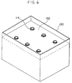
- a board 192 such as that illustrated in Fig. 6, in which a plurality of holes are formed so that the end portions of the container opening portions 114 (or 154) protrude therefrom, may be placed within a corrugated fiberboard box 190 so as to prevent the containers from shifting. Abrasion of the containers which occurs during transport thereof can thereby be controlled.
- the caps are unillustrated in Fig. 6.
- the bellows portion has five levels of convex portions.
- the number of convex and concave portions forming the bellows portion is preferably 2 through 10, and more preferably 4 through 6.
- the entire configuration nears a cylindrical shape, and the rate of increase of the specific surface area (using a cylindrical container of the same internal volume as a standard) can be reduced. This is preferable from the standpoint of reducing the oxygen transmission rate, and is suitable for the storing of developing solutions and the like. In particular, it is preferable that there are fewer convex portions when developing solutions are stored.
- the container for a liquid relating to the present invention is filled with a processing solution (this will be described in further detail later) used in the developing processing of a photosensitive material.
- the container for a liquid can be used as a container for beverages which is filled with any of various of types of beverages.
- the container for a liquid of the present invention can also be used for flowing substances such as mayonnaise, jam or the like, or for semi-flowing substances.
- the internal volume of the container for a liquid can be applied to containers of a wide range of internal volumes from 50 milliliters to several liters (more specifically, 2 to 5 liters for example).
- processing chemicals for photography can be filled in the container for a liquid relating to the present invention.
- chemicals to which "the present invention can be applied" Color developing solutions, black-and-white developing solutions, bleaching solutions, fixing solutions, bleaching/fixing solutions, regulating solutions, stabilizers and the like can be given as examples of chemicals to which the present invention may be applied.
- the color developing solution to which the present invention is applied is preferably an alkaline aqueous solution whose main component is an aromatic primary amine color developing agent.
- Aminophenol compounds may be used as the color developing agent, and p-phenylenediamine compounds are preferable.
- Typical examples include 3-methyl-4-amino-N,N-diethylaniline, 3-methyl-4-amino-N-ethyl-N- ⁇ -hydroxyethylaniline, 3-methyl-4-amino-N-ethyl-N- ⁇ -methansulfonamideethylaniline, 3-methyl-4-amino-N-ethyl-N- ⁇ -methoxyethylaniline and their sulfates, hydrochloric acid salts or p-toluenesulfonic acid salts. Two or more of these compounds may be used together in accordance with the object thereof.
- Color developing chemicals generally contain pH buffers such as carbonates, borates or phosphates of alkali metals; development inhibitors such as bromide salts, iodide salts, benzimidazoles, benzithiazoles, and mercapto compounds; and antifoggants and the like.
- preservatives such as hydroxylamine, diethylhydroxylamine, hydrazine sulfites, phenylsemicarbazides, triethanolamine, catecholsulfonic acids, triethylenediamine(1,4-diazabicyclo[2,2,2]octane) and the like; organic solvents such as ethylene glycol and diethylene glycol; development accelerators such as quaternary ammonium salts and amines; dye forming couplers, competitive couplers; fogging agents such as sodium borohydride; auxiliary developing agents such as 1-phenyl-3-pyrazolidone; thickening agents; various types of chelating agents such as aminopolycarboxylic acid, aminopolyphosphonic acid, alkylphosphonic acid, phosphonocarboxylic acid, and for example, ethylenediaminetetraacetic acid, nitrilotriacetic acid, diethylenetriaminopentaacetic acid, cycl
- black-and-white developing agents can be used alone, or combinations thereof can be used.
- Examples of commonly-known black-and-white developing agents include dihydroxybenzenes such as hydroquinone, 3-pyrazolidones such as 1-phenyl-3-pyrazolidone, aminophenols such as N-methyl-p-aminophenol, and the like.
- Polyvalent metal compounds such as iron (III), peroxides, and the like can be used as a bleaching agent.
- Representative bleaching agents include organic complex salts of iron (III) (e.g., complex salts of aminopolycarboxylic acids such as ethylenediamine tetraacetate, diethylenetriamene pentaacetate, cyclohexanediamine tetraacetate, methyliminodiacetate, 1,3-diaminopropane tetraacetate, and glycoletherdiamine tetraacetate), persulfates, and the like.
- Aminopolycarboxylic acid iron (III) complex salt is particularly useful in bleaching solution and in bleaching/fixing solution.
- fixing agents include thiosulfate, thiocyanate, thioether compounds, thioureas, a large amount of iodide salts, and the like.
- thiosulfate is used, and ammonium thiosulfate in particular has the widest range of use.
- sulfurous acid salt bisulfite, sulfinic acids or carbonylbisulfite addition products.
- processing solutions such as color developing solutions, bleaching/fixing solutions and the like to which the present invention may be applied are disclosed in "Photographic Industry Supplement: Handbook of the Latest Photographic Preparations” by Akira Sasai, (Photographic Industry Publishing Co., July 20, 1983).
- Color developing solutions, bleaching solutions, fixing solutions, and stabilizing solutions for color negative film disclosed in Japanese Patent Application Laid-Open No. 4-359249 (in particular, the color developing replenishing solution, the bleaching replenishing solution, the fixing replenishing solution and stabilizing solution No. 18 disclosed in the first embodiment) can be used.
- the solutions may be stored as they are in the container, or may be concentrated and then stored.
- the above-mentioned stabilizing solution No. 18 may be concentrated 100 times.
- Color developing solutions and bleaching/fixing solutions for color paper disclosed in Japanese Patent Application Laid-Open No. 4-195037 in the embodiments, and in particular, the color developing replenishing solution and the bleaching/fixing replenishing solution disclosed in the second embodiment) can be used.
- color developing solutions As for color developing solutions, bleaching/fixing solutions, and washing water for use with direct positive color photosensitive materials, the following can be used: the color developing replenishing solutions disclosed in Japanese Patent Application Laid-Open No. 1-93739 (those in the embodiments, and in particular, the color developing replenishing solutions disclosed in the second embodiment); the color developing replenishing solutions disclosed in Japanese Application Laid-Open No. 2-50157 (those in the embodiments, and in particular, the color developing replenishing solutions of the fourth embodiment, more particularly, CD-20); the color developing replenishing solutions disclosed in Japanese Patent Application Laid-Open No. 2-91642 (those in the embodiments, and in particular, the color developing replenishing solutions of the first embodiment, more particularly No.
- bleaching/fixing solutions disclosed in Japanese Patent Application Laid-Open No. 3-13941 examples in the embodiments, and in particular, the bleaching/fixing solutions of the first embodiment
- washing water disclosed in Japanese Patent Application Laid-Open No. 3-13941 in particular, washing water disclosed in the first embodiment.
- These processing solutions may be stored as they are in the container, or may be concentrated and stored.
Landscapes
- Engineering & Computer Science (AREA)
- Ceramic Engineering (AREA)
- Mechanical Engineering (AREA)
- Photographic Developing Apparatuses (AREA)
- Containers Having Bodies Formed In One Piece (AREA)
Claims (12)
- Récipient pour un liquide comportant :un corps principal de récipient flexible (112) ayant une partie de soufflet (116) au niveau d'au moins une partie de direction axiale dudit corps principal de récipient (112); etune partie d'ouverture rigide (114) formée d'un seul tenant avec ledit corps principal de récipient de façon à dépasser dudit corps principal de récipient, ladite partie de soufflet (116) étant formée par une multiplicité de parties convexes annulaires (118, 120, 122, 124, 126) qui sont disposées à des intervalles prédéterminés le long de la direction axiale dudit corps principal de récipient (112),
caractérisé en ce que :des parties (118A, 118B, 120A, 120B, 124A, 124B, 126A, 126B) ayant des rayons de courbure sont formées au niveau de chacune desdites parties convexes annulaires (118, 120, 122, 124, 126) au niveau d'un côté de direction axiale d'un voisinage d'une partie de dépassement maximum, qui dépasse dans une direction perpendiculaire à une direction axiale, et au niveau d'un autre côté de direction axiale du voisinage de la partie de dépassement maximum, les parties (118A, 118B, 120A, 120B, 122A, 122B, 124A, 124B, 126A, 126B) d'au moins une desdites parties convexes annulaires (118, 120, 122, 124 et 126) ayant des rayons de courbure différents, et les dimensions extérieures de la partie de soufflet jusqu'à la partie de soufflet supérieure, une rainure concave (136, 138, 140, 142) étant formée dans chacune desdites parties convexes annulaires le long d'une périphérie entière d'un côté de direction axiale de ladite partie saillante annulaire ou bien un autre côté de direction axiale de ladite partie saillante annulaire. - Récipient (110) pour un liquide selon la revendication 1, ledit récipient étant caractérisé en ce que ladite partie de soufflet (116) est formée de manière continue depuis une partie de bordure entre ledit corps principal de récipient (112) et ladite partie d'ouverture (114) jusqu'à une partie inférieure dudit corps principal de récipient (112).
- Récipient (110) pour un liquide selon la revendication 1, ledit récipient étant caractérisé en ce qu'une partie de rebord (144), qui dépasse d'un certain degré dans une direction perpendiculaire à la direction axiale, est formée au niveau d'une partie de direction axiale de ladite partie d'ouverture (114).
- Récipient pour un liquide selon la revendication 1, ledit récipient étant caractérisé en ce qu'une partie (144), dont la section dans une direction perpendiculaire à la direction axiale n'est pas circulaire, est prévue au niveau d'une partie de direction axiale de ladite partie d'ouverture.
- Récipient pour un liquide selon la revendication 1, ledit récipient étant caractérisé en ce qu'un rapport d'une épaisseur moyenne d'une partie de base d'ouverture qui comprend ladite partie d'ouverture (114) et un voisinage de ladite partie d'ouverture (114) sur une épaisseur moyenne dudit corps principal de récipient (112) est d'environ 2,0 à 10,0.
- Récipient pour un liquide selon la revendication 1, ledit récipient étant caractérisé en ce qu'une configuration en coupe dudit corps principal de récipient (112) dans une direction perpendiculaire à la direction axiale n'est pas circulaire.
- Récipient pour un liquide selon la revendication 1, ledit récipient étant caractérise en ce que ladite partie de soufflet (116) est moulée par soufflage et est ajustée par commande de la paraison de telle sorte que le rapport de l'épaisseur des parties de raccordement (128, 130, 132, 134) qui sont les plus proches de l'axe central sur l'épaisseur des parties desdites parties convexes annulaires (118, 120, 122, 124, 126) qui sont les plus éloignées de l'axe central est d'environ 1,1 à 5.
- Récipient selon la revendication 1, ledit récipient étant caractérisé en ce qu'une coupe dans une direction perpendiculaire à la direction axiale de chacune desdites parties convexes annulaires (118, 120, 122, 124, 126) est sensiblement rectangulaire, et lesdites parties annulaires de dépassement maximum desdites parties convexes annulaires (113, 120, 122, 124, 126) ont une même taille et une même configuration de façon a être placées dans un agencement superposé vu depuis la direction axiale, et une dimension de direction axiale d'un côté de partie d'ouverture de ladite partie annulaire de dépassement maximum ou d'un côté de ladite partie annulaire de dépassement maximum opposé au côté de partie d'ouverture est plus grande qu'une dimension de direction axiale de l'autre côté de partie d'ouverture de ladite partie annulaire de dépassement maximum ou du côté de ladite partie annulaire de dépassement maximum opposée au côté de partie d'ouverture.
- Récipient pour un liquide selon la revendication 1, ledit récipient étant caractérisé en ce que ladite partie de soufflet (116) est formée par plusieurs parties convexes annulaires (118, 120, 122, 124, 126) et des parties de raccordement annulaires (128, 130, 132, 134), ladite multiplicité de parties convexes annulaires étant disposées à des intervalles prédéterminés le long de la direction axiale dudit corps principal de récipient, lesdites parties de raccordement annulaires (128, 130, 132, 134) reliant des parties adjacentes desdites parties convexes annulaires au niveau des parties de dépassement minimum qui dépassent d'une valeur minimum dans la direction perpendiculaire à la direction axiale des deux extrémités de direction axiale desdites parties convexes annulaires, et dans lequelun diamètre de chacune des parties de raccordement annulaires (128, 130, 132, 134) formant ladite partie de soufflet n'est pas supérieur à 85 % d'un diamètre maximum des parties convexes annulaires (118, 120, 122, 124, 126) au niveau d'un côté de partie d'ouverture auquel est relié ladite partie de raccordement annulaire.
- Récipient pour un liquide selon la revendication 1, ledit récipient étant caractérisé en ce que ledit récipient comprend en outre des parties de raccordement (128, 130, 132, 134) destinés à relier lesdites parties convexes annulaires au niveau des parties de dépassement minimum de celles-ci, une épaisseur desdites parties de raccordement étant supérieure à une épaisseur de parties desdites parties convexes annulaires (118, 120, 122, 124, 126) qui sont éloignées d'un axe central dudit récipient.
- Récipient selon la revendication 1, ledit récipient étant caractérisé en ce que ladite multiplicité de parties convexes annulaires est reliée l'une à l'autre par des parties de raccordement annulaires (128, 130, 132, 134).
- Récipient selon la revendication 1, ledit récipient étant caractérisé en ce que lesdites parties convexes annulaires (118, 120, 122, 124, 126) sont reliées l'une à l'autre au niveau de parties, qui sont plus proches d'un axe central, des deux extrémités de direction axiale desdites parties convexes annulaires (118, 120, 122, 124, 126).
Applications Claiming Priority (9)
| Application Number | Priority Date | Filing Date | Title |
|---|---|---|---|
| JP3066493 | 1993-02-19 | ||
| JP30664/93 | 1993-02-19 | ||
| JP3066493 | 1993-02-19 | ||
| JP142394/93 | 1993-06-14 | ||
| JP14239493 | 1993-06-14 | ||
| JP14239493A JP3155396B2 (ja) | 1993-06-14 | 1993-06-14 | 写真処理組成物用容器 |
| JP14239993 | 1993-06-14 | ||
| JP142399/93 | 1993-06-14 | ||
| JP5142399A JPH06301189A (ja) | 1993-02-19 | 1993-06-14 | 液体用容器 |
Publications (2)
| Publication Number | Publication Date |
|---|---|
| EP0611700A1 EP0611700A1 (fr) | 1994-08-24 |
| EP0611700B1 true EP0611700B1 (fr) | 1999-09-15 |
Family
ID=27287051
Family Applications (1)
| Application Number | Title | Priority Date | Filing Date |
|---|---|---|---|
| EP94102504A Expired - Lifetime EP0611700B1 (fr) | 1993-02-19 | 1994-02-18 | Récipient pour liquides |
Country Status (3)
| Country | Link |
|---|---|
| US (1) | US5573129A (fr) |
| EP (1) | EP0611700B1 (fr) |
| DE (1) | DE69420597T2 (fr) |
Families Citing this family (82)
| Publication number | Priority date | Publication date | Assignee | Title |
|---|---|---|---|---|
| CH687073A5 (de) * | 1993-04-02 | 1996-09-13 | Vogel Bmw Ag | Stauchbarer Behaelter. |
| SE523785C2 (sv) | 1995-02-07 | 2004-05-18 | Plastech Aps | Metod och anordning för att framställa en rörformad behållare med tillslutningsorgan |
| US6105815A (en) * | 1996-12-11 | 2000-08-22 | Mazda; Masayosi | Contraction-controlled bellows container |
| EP0850842A1 (fr) * | 1996-12-27 | 1998-07-01 | Masayosi Mazda | Recipient en accordéon contractible |
| JP3108377B2 (ja) | 1997-01-15 | 2000-11-13 | 芳雄 臼井 | 圧潰性プラスチックボトル |
| US6177043B1 (en) * | 1997-12-08 | 2001-01-23 | Laverne E. Woock | Method for producing flexible decoys |
| US6105778A (en) * | 1998-03-04 | 2000-08-22 | Tsai; Daniel E. | Protective pouch |
| US5927499A (en) * | 1998-05-29 | 1999-07-27 | Colgate-Palmolive Company | Hydrostatic containers |
| CA2248297A1 (fr) | 1998-09-22 | 2000-03-22 | Simon Schillaci | Contenant portable |
| US6491047B2 (en) * | 1998-11-13 | 2002-12-10 | Fuji Photo Film Co., Ltd. | Method of cleaning container for photographic treatment composition and apparatus therefor |
| ITMI990142A1 (it) * | 1999-01-27 | 2000-07-27 | Christian Pio Pedulla | Bottiglia-contenitore salva gas e spazio |
| US6378736B1 (en) | 2000-01-14 | 2002-04-30 | Ronald Crosslin | Collapsible fuel container |
| US6662964B2 (en) | 2000-08-28 | 2003-12-16 | Gohsho Company, Ltd. | Synthetic resin liquid container |
| TWI228476B (en) * | 2000-08-31 | 2005-03-01 | Co2 Pac Ltd | Semi-rigid collapsible container |
| US10246238B2 (en) | 2000-08-31 | 2019-04-02 | Co2Pac Limited | Plastic container having a deep-set invertible base and related methods |
| NZ521694A (en) | 2002-09-30 | 2005-05-27 | Co2 Pac Ltd | Container structure for removal of vacuum pressure |
| US8381940B2 (en) | 2002-09-30 | 2013-02-26 | Co2 Pac Limited | Pressure reinforced plastic container having a moveable pressure panel and related method of processing a plastic container |
| AU2002257159B2 (en) | 2001-04-19 | 2007-03-01 | Graham Packaging Company, L.P. | Multi-functional base for a plastic wide-mouth, blow-moulded container |
| EP1461285A4 (fr) * | 2001-12-06 | 2005-05-25 | Gabriel Cabelli | Recipients de distribution de fluide portatifs |
| JP4016248B2 (ja) * | 2001-12-27 | 2007-12-05 | 株式会社江商 | 長さ方向が縮小された状態を保つことが可能な容器とその縮小方法 |
| GB0220448D0 (en) * | 2002-09-04 | 2002-10-09 | Eggleden John A | Fluid dispenser |
| US9969517B2 (en) | 2002-09-30 | 2018-05-15 | Co2Pac Limited | Systems and methods for handling plastic containers having a deep-set invertible base |
| US6935525B2 (en) * | 2003-02-14 | 2005-08-30 | Graham Packaging Company, L.P. | Container with flexible panels |
| DE10324893A1 (de) * | 2003-05-30 | 2004-12-16 | Kempa, Josef | Flasche mit Komponenten, um sie rationeller entsorgen zu können |
| ITMI20031185A1 (it) * | 2003-06-12 | 2004-12-13 | Gianfilippo Pagliacci | Contenitore monouso progressivamente collassabile perfezionato. |
| US7654402B2 (en) * | 2003-12-16 | 2010-02-02 | Dart Industries Inc. | Collapsible container |
| CZ298274B6 (cs) * | 2003-12-22 | 2007-08-15 | Kinyo Holding Inc. | Plastová skládací láhev s harmonikově uspořádanými žebry |
| US20050198930A1 (en) * | 2004-03-10 | 2005-09-15 | Mitsuo Higuchi | Distribution system of pet bottle for drinking water and beverage |
| US20060118509A1 (en) * | 2004-08-31 | 2006-06-08 | Consumer Innovation Partners, Lp | Semi-collapsible container |
| US7993304B2 (en) * | 2006-03-15 | 2011-08-09 | Bioquiddity, Inc. | Fluid dispensing apparatus |
| US7828772B2 (en) * | 2006-03-15 | 2010-11-09 | Bioquiddity, Inc. | Fluid dispensing device |
| US7793617B2 (en) * | 2006-05-31 | 2010-09-14 | Venezia Alberto J | Collapsible wildlife containment apparatus |
| US7905305B2 (en) * | 2006-07-07 | 2011-03-15 | Mattel, Inc. | Blow-molded wheels having undulating treads, methods for producing the same, and children's ride-on vehicles including the same |
| US7621543B2 (en) * | 2006-08-23 | 2009-11-24 | Mattel, Inc. | Blow-molded wheels having undercut treads, methods for producing the same, and children's ride-on vehicles including the same |
| JP5006335B2 (ja) * | 2006-11-17 | 2012-08-22 | オリンパスメディカルシステムズ株式会社 | 消毒液用ボトル及び内視鏡洗浄消毒装置 |
| US11897656B2 (en) | 2007-02-09 | 2024-02-13 | Co2Pac Limited | Plastic container having a movable base |
| US8439214B2 (en) * | 2007-03-16 | 2013-05-14 | Plastipak Packaging, Inc. | Plastic container with elongated vertical formation |
| AU2007357858B2 (en) * | 2007-08-17 | 2014-05-22 | Sea To Summit Pty Ltd | Collapsible container |
| US20090112149A1 (en) * | 2007-10-31 | 2009-04-30 | Kriesel Marshall S | Variable rate fluid dispenser |
| US20100108699A1 (en) * | 2008-10-30 | 2010-05-06 | Dennis Stephen R | Compression-Resistant Container |
| WO2010069040A1 (fr) * | 2008-11-18 | 2010-06-24 | Gerard Grand | Poids d'entraînement pliant et extensible |
| US20110230317A9 (en) * | 2008-12-08 | 2011-09-22 | Stephen Barber | Adjustable fluid-fillable exercise weights |
| WO2012009416A2 (fr) * | 2010-07-16 | 2012-01-19 | Amcor Limited | Formation instantanée à base contrôlée d'une bague dressée |
| US9498570B2 (en) | 2010-10-25 | 2016-11-22 | Bayer Healthcare Llc | Bladder syringe fluid delivery system |
| WO2012061140A1 (fr) | 2010-10-25 | 2012-05-10 | Medrad, Inc. | Système de distribution de fluide à seringue à vessie |
| US8763829B2 (en) * | 2011-07-22 | 2014-07-01 | Craig Allen Madaus | Collapsible container for holding liquids or objects |
| US20130068717A1 (en) * | 2011-09-16 | 2013-03-21 | Curtis Lee Hipkins | Scrunchable plastic disposable carbonated beverage bottle |
| GB2498962A (en) * | 2012-01-31 | 2013-08-07 | Team Grasshopper Ltd | An expandable container |
| US9180252B2 (en) | 2012-04-20 | 2015-11-10 | Bayer Medical Care Inc. | Bellows syringe fluid delivery system |
| US9119507B2 (en) * | 2013-08-11 | 2015-09-01 | Urban Tumbler LLC | Collapsible travel tumbler |
| DE102013109378A1 (de) * | 2013-08-29 | 2015-03-05 | Krones Ag | Verfahren zum Herstellen von mit einer Flüssigkeit befüllten Behältnissen |
| US10258203B2 (en) * | 2014-02-07 | 2019-04-16 | Gojo Industries, Inc. | Dispenser and container |
| AU2015249322B2 (en) | 2014-04-25 | 2020-01-30 | Bayer Healthcare Llc | Syringe with rolling diaphragm |
| CN104309882A (zh) * | 2014-10-15 | 2015-01-28 | 佛山市天晟隆油脂化工有限公司 | 一种黄油枪用的润滑脂包装瓶 |
| CN104309881A (zh) * | 2014-10-15 | 2015-01-28 | 佛山市天晟隆油脂化工有限公司 | 一种黄油枪用的润滑脂包装瓶 |
| CN104309884A (zh) * | 2014-10-15 | 2015-01-28 | 佛山市天晟隆油脂化工有限公司 | 一种黄油枪用的润滑脂包装瓶 |
| CN104309883A (zh) * | 2014-10-15 | 2015-01-28 | 佛山市天晟隆油脂化工有限公司 | 一种黄油枪用的润滑脂包装瓶 |
| JP6731943B2 (ja) | 2015-04-24 | 2020-07-29 | バイエル・ヘルスケア・エルエルシーBayer HealthCare LLC | まくりダイアフラムを有するシリンジ |
| USD777520S1 (en) * | 2015-06-18 | 2017-01-31 | Hydaway, LLC | Beverage container |
| USD779886S1 (en) * | 2015-12-08 | 2017-02-28 | Hydaway, LLC | Beverage container |
| US9969521B2 (en) * | 2016-05-06 | 2018-05-15 | Yang Shen | Helically collapsible beverage bottle |
| CN105775296B (zh) * | 2016-05-11 | 2018-08-24 | 黄楚铭 | 一种容器 |
| IL246809A (en) | 2016-07-17 | 2017-08-31 | Moshe Amsellem Maurice | Clamping facility for compressed plastic bottles for recycling |
| GB201615043D0 (en) * | 2016-09-05 | 2016-10-19 | Formabowl Llp | Improved container |
| TWI737812B (zh) | 2016-09-16 | 2021-09-01 | 美商拜耳保健公司 | 具有注射保持元件之壓力套及用於將流體輸送給一患者之流體注入器 |
| WO2018075386A1 (fr) | 2016-10-17 | 2018-04-26 | Bayer Healthcare Llc | Injecteur de fluide avec mécanisme de mise en prise de seringue |
| CN114588394A (zh) | 2016-10-17 | 2022-06-07 | 拜耳医药保健有限公司 | 具有针筒接合机构的流体注射器 |
| AU2018334143B2 (en) | 2017-09-13 | 2024-03-21 | Bayer Healthcare Llc | Sliding syringe cap for separate filling and delivery |
| USD898301S1 (en) * | 2018-05-15 | 2020-10-06 | Meili Peng | Feeder for birds |
| USD867606S1 (en) | 2018-06-08 | 2019-11-19 | Collapseandgo, LLC | Collapsible liquid container |
| US10611564B1 (en) | 2019-01-02 | 2020-04-07 | Dooli Products, LLC | Height adjustable waste disposal device with bag-grabbing membrane |
| WO2021050507A1 (fr) | 2019-09-10 | 2021-03-18 | Bayer Healthcare Llc | Gaines de pression et caractéristiques de retenue de seringue pour injecteurs de fluide d'angiographie |
| SI25660A (sl) | 2019-09-27 | 2019-12-31 | Puhar Miha | Raztegljiva embalaža in embalažna posoda, postopek njene uporabe in postopek njene izdelave |
| US11008162B1 (en) | 2020-02-03 | 2021-05-18 | Dooli Products, LLC | Baby and adult-safe waste container with bag handling odor control assembly |
| USD895919S1 (en) | 2020-02-07 | 2020-09-08 | Dooli Products, LLC | Container with a lid |
| USD895918S1 (en) | 2020-02-07 | 2020-09-08 | Dooli Products, LLC | Vertically oriented container with a lid |
| EP4106857A1 (fr) | 2020-02-21 | 2022-12-28 | Bayer HealthCare, LLC | Raccords de trajet de fluide permettant l'administration de fluide médical |
| IL299062A (en) | 2020-06-18 | 2023-02-01 | Bayer Healthcare Llc | Built-in air bubble suspension device for angiography syringe fluid paths |
| USD940506S1 (en) * | 2020-06-25 | 2022-01-11 | Hydaway, LLC | Collapsible tumbler |
| US11535415B2 (en) | 2021-03-16 | 2022-12-27 | Berlin Packaging, Llc | Compressible and expandable bottle |
| USD998472S1 (en) | 2021-03-17 | 2023-09-12 | Berlin Packaging, Llc | Expandable bottle |
| CN117999231A (zh) * | 2021-09-27 | 2024-05-07 | 即时品牌控股有限公司 | 容器 |
Family Cites Families (26)
| Publication number | Priority date | Publication date | Assignee | Title |
|---|---|---|---|---|
| GB558915A (en) * | 1942-06-24 | 1944-01-27 | Edwin Sassoon Solomon | Improvements relating to dish washing and like machines |
| US2857080A (en) * | 1955-06-10 | 1958-10-21 | Nathaniel M Elias | Flexible containers |
| BE558915A (fr) * | 1956-07-13 | |||
| US3083877A (en) * | 1960-10-25 | 1963-04-02 | Moulded Products Australasia L | Collapsible container with corrugations to facilitate the collapse of its walls |
| US3143429A (en) * | 1961-10-09 | 1964-08-04 | Pillsbury Co | Collapsible disposable container and nursing unit |
| US3270905A (en) * | 1962-12-12 | 1966-09-06 | Sealol | Pressure container |
| US3301293A (en) * | 1964-12-16 | 1967-01-31 | Owens Illinois Inc | Collapsible container |
| CH586133A5 (en) * | 1975-07-21 | 1977-03-31 | Cheddite Plastic Ag | Filling of powder material into flexible container - has container in form of folding bellows enlarged during filling by expanding device |
| DE2659594A1 (de) * | 1976-07-03 | 1978-01-05 | Toho Kk | Zusammenlegbarer behaelter |
| US4394906A (en) * | 1981-06-23 | 1983-07-26 | Hollenbeck John C | Food container/holder |
| US4526296A (en) * | 1981-12-07 | 1985-07-02 | Berger Richard F | Flexible pleated container structure |
| US4492313A (en) * | 1984-05-29 | 1985-01-08 | William Touzani | Collapsible bottle |
| US4775564A (en) * | 1985-03-11 | 1988-10-04 | The Goodyear Tire & Rubber Company | Collapsible-stable blown container |
| US4790361A (en) * | 1986-07-25 | 1988-12-13 | Containers Unlimited | Collapsible carbonated beverage container |
| US4773458A (en) * | 1986-10-08 | 1988-09-27 | William Touzani | Collapsible hollow articles with improved latching and dispensing configurations |
| FR2607109A1 (fr) * | 1986-11-24 | 1988-05-27 | Castanet Jean Noel | Bouteille a volume variable specialement en matiere plastique et son procede de fabrication |
| FR2609450A1 (fr) * | 1987-01-09 | 1988-07-15 | Ludi Jean Claude | Recipient pour liquides pliable, avec auto-blocage en position pliee |
| US4887730A (en) * | 1987-03-27 | 1989-12-19 | William Touzani | Freshness and tamper monitoring closure |
| US4873100A (en) * | 1987-04-15 | 1989-10-10 | The Procter & Gamble Company | Bistable expandable bottle |
| US5027963A (en) * | 1988-12-22 | 1991-07-02 | Robbins Edward S Iii | Containers having one or more integral annular bands of increased thickness |
| US4921147A (en) * | 1989-02-06 | 1990-05-01 | Michel Poirier | Pouring spout |
| US4955493A (en) * | 1989-08-15 | 1990-09-11 | Touzani William N | Collapsible expansible plastic hollow articles in a latchable configuration |
| US5198161A (en) * | 1990-03-07 | 1993-03-30 | Kao Corporation | Parison thickness control method |
| JPH04102544A (ja) * | 1990-08-02 | 1992-04-03 | Hoei Kogyo Kk | 可圧潰缶 |
| GB2250259A (en) * | 1990-10-11 | 1992-06-03 | John Allan Inskip | Variable volume container |
| US5348173A (en) * | 1991-09-20 | 1994-09-20 | Norwood Peter M | Collapsible-stackable plastic container |
-
1994
- 1994-02-18 DE DE69420597T patent/DE69420597T2/de not_active Expired - Fee Related
- 1994-02-18 US US08/199,343 patent/US5573129A/en not_active Expired - Lifetime
- 1994-02-18 EP EP94102504A patent/EP0611700B1/fr not_active Expired - Lifetime
Also Published As
| Publication number | Publication date |
|---|---|
| DE69420597D1 (de) | 1999-10-21 |
| US5573129A (en) | 1996-11-12 |
| DE69420597T2 (de) | 2000-02-17 |
| EP0611700A1 (fr) | 1994-08-24 |
Similar Documents
| Publication | Publication Date | Title |
|---|---|---|
| EP0611700B1 (fr) | Récipient pour liquides | |
| US7234592B2 (en) | Photographic processing agent cartridge and container usable therein | |
| EP1561691A1 (fr) | Bouteille en resine synthetique | |
| JP3122274B2 (ja) | パトローネ収納容器 | |
| JP3310369B2 (ja) | 液体用容器 | |
| JP2003072785A (ja) | 注出容器 | |
| JP3229713B2 (ja) | 写真処理組成物用容器 | |
| CA2472503C (fr) | Cartouche d'agent servant au developpement photographique et contenant utilisable a cet egard | |
| JP3155396B2 (ja) | 写真処理組成物用容器 | |
| JPH06247448A (ja) | 流体用容器 | |
| JPH06301189A (ja) | 液体用容器 | |
| JP2010126224A (ja) | 飲料水容器 | |
| JP3283944B2 (ja) | 流体用容器 | |
| JPH11130035A (ja) | 薄肉容器 | |
| US20050133530A1 (en) | Package for photographic processing chemicals | |
| US20050133533A1 (en) | Package for photographic processing chemicals | |
| JP2007045451A (ja) | 自立袋 | |
| JPH075665A (ja) | 写真処理組成物用容器 | |
| JPH06242587A (ja) | 液体用容器 | |
| JPH075664A (ja) | 写真処理組成物用容器 | |
| JPH075666A (ja) | 写真処理組成物用容器 | |
| WO2022025277A1 (fr) | Contenant double | |
| JP2022026895A (ja) | 二重容器 | |
| JP2019077451A (ja) | 樹脂製容器 | |
| JP4877492B2 (ja) | 自立袋形ブロー成形減容容器 |
Legal Events
| Date | Code | Title | Description |
|---|---|---|---|
| PUAI | Public reference made under article 153(3) epc to a published international application that has entered the european phase |
Free format text: ORIGINAL CODE: 0009012 |
|
| AK | Designated contracting states |
Kind code of ref document: A1 Designated state(s): BE DE FR GB NL |
|
| 17P | Request for examination filed |
Effective date: 19941220 |
|
| 17Q | First examination report despatched |
Effective date: 19960502 |
|
| GRAG | Despatch of communication of intention to grant |
Free format text: ORIGINAL CODE: EPIDOS AGRA |
|
| GRAG | Despatch of communication of intention to grant |
Free format text: ORIGINAL CODE: EPIDOS AGRA |
|
| GRAH | Despatch of communication of intention to grant a patent |
Free format text: ORIGINAL CODE: EPIDOS IGRA |
|
| GRAH | Despatch of communication of intention to grant a patent |
Free format text: ORIGINAL CODE: EPIDOS IGRA |
|
| GRAA | (expected) grant |
Free format text: ORIGINAL CODE: 0009210 |
|
| AK | Designated contracting states |
Kind code of ref document: B1 Designated state(s): BE DE FR GB NL |
|
| PG25 | Lapsed in a contracting state [announced via postgrant information from national office to epo] |
Ref country code: NL Free format text: LAPSE BECAUSE OF FAILURE TO SUBMIT A TRANSLATION OF THE DESCRIPTION OR TO PAY THE FEE WITHIN THE PRESCRIBED TIME-LIMIT Effective date: 19990915 Ref country code: FR Free format text: LAPSE BECAUSE OF FAILURE TO SUBMIT A TRANSLATION OF THE DESCRIPTION OR TO PAY THE FEE WITHIN THE PRESCRIBED TIME-LIMIT Effective date: 19990915 Ref country code: BE Free format text: LAPSE BECAUSE OF FAILURE TO SUBMIT A TRANSLATION OF THE DESCRIPTION OR TO PAY THE FEE WITHIN THE PRESCRIBED TIME-LIMIT Effective date: 19990915 |
|
| REF | Corresponds to: |
Ref document number: 69420597 Country of ref document: DE Date of ref document: 19991021 |
|
| NLV1 | Nl: lapsed or annulled due to failure to fulfill the requirements of art. 29p and 29m of the patents act | ||
| EN | Fr: translation not filed | ||
| PLBE | No opposition filed within time limit |
Free format text: ORIGINAL CODE: 0009261 |
|
| STAA | Information on the status of an ep patent application or granted ep patent |
Free format text: STATUS: NO OPPOSITION FILED WITHIN TIME LIMIT |
|
| 26N | No opposition filed | ||
| REG | Reference to a national code |
Ref country code: GB Ref legal event code: IF02 |
|
| REG | Reference to a national code |
Ref country code: GB Ref legal event code: 732E |
|
| PGFP | Annual fee paid to national office [announced via postgrant information from national office to epo] |
Ref country code: GB Payment date: 20080123 Year of fee payment: 15 |
|
| PGFP | Annual fee paid to national office [announced via postgrant information from national office to epo] |
Ref country code: DE Payment date: 20080320 Year of fee payment: 15 |
|
| GBPC | Gb: european patent ceased through non-payment of renewal fee |
Effective date: 20090218 |
|
| PG25 | Lapsed in a contracting state [announced via postgrant information from national office to epo] |
Ref country code: DE Free format text: LAPSE BECAUSE OF NON-PAYMENT OF DUE FEES Effective date: 20090901 |
|
| PG25 | Lapsed in a contracting state [announced via postgrant information from national office to epo] |
Ref country code: GB Free format text: LAPSE BECAUSE OF NON-PAYMENT OF DUE FEES Effective date: 20090218 |