EP0609552B1 - Fermeture frontale pour armoires électriques, supports châssis ou similaires - Google Patents
Fermeture frontale pour armoires électriques, supports châssis ou similaires Download PDFInfo
- Publication number
- EP0609552B1 EP0609552B1 EP93120700A EP93120700A EP0609552B1 EP 0609552 B1 EP0609552 B1 EP 0609552B1 EP 93120700 A EP93120700 A EP 93120700A EP 93120700 A EP93120700 A EP 93120700A EP 0609552 B1 EP0609552 B1 EP 0609552B1
- Authority
- EP
- European Patent Office
- Prior art keywords
- circuit board
- printed circuit
- limb
- earth
- contact
- Prior art date
- Legal status (The legal status is an assumption and is not a legal conclusion. Google has not performed a legal analysis and makes no representation as to the accuracy of the status listed.)
- Expired - Lifetime
Links
- 125000006850 spacer group Chemical group 0.000 claims abstract description 16
- 239000004020 conductor Substances 0.000 claims abstract description 10
- 230000001681 protective effect Effects 0.000 claims description 11
- 230000007704 transition Effects 0.000 claims description 2
- 238000012216 screening Methods 0.000 claims 6
- 230000000712 assembly Effects 0.000 claims 1
- 238000000429 assembly Methods 0.000 claims 1
- 230000008878 coupling Effects 0.000 claims 1
- 238000010168 coupling process Methods 0.000 claims 1
- 238000005859 coupling reaction Methods 0.000 claims 1
- 239000002184 metal Substances 0.000 abstract description 4
- 238000000926 separation method Methods 0.000 abstract 1
- 210000001364 upper extremity Anatomy 0.000 description 21
- 230000012447 hatching Effects 0.000 description 3
- 230000000149 penetrating effect Effects 0.000 description 2
- 238000003466 welding Methods 0.000 description 2
- 230000015572 biosynthetic process Effects 0.000 description 1
- 210000001061 forehead Anatomy 0.000 description 1
- 238000009434 installation Methods 0.000 description 1
- 239000011241 protective layer Substances 0.000 description 1
- 230000005855 radiation Effects 0.000 description 1
- 238000007142 ring opening reaction Methods 0.000 description 1
- 238000005476 soldering Methods 0.000 description 1
- 210000003462 vein Anatomy 0.000 description 1
Images
Classifications
-
- H—ELECTRICITY
- H05—ELECTRIC TECHNIQUES NOT OTHERWISE PROVIDED FOR
- H05K—PRINTED CIRCUITS; CASINGS OR CONSTRUCTIONAL DETAILS OF ELECTRIC APPARATUS; MANUFACTURE OF ASSEMBLAGES OF ELECTRICAL COMPONENTS
- H05K1/00—Printed circuits
- H05K1/02—Details
- H05K1/0213—Electrical arrangements not otherwise provided for
- H05K1/0216—Reduction of cross-talk, noise or electromagnetic interference
- H05K1/0218—Reduction of cross-talk, noise or electromagnetic interference by printed shielding conductors, ground planes or power plane
-
- H—ELECTRICITY
- H02—GENERATION; CONVERSION OR DISTRIBUTION OF ELECTRIC POWER
- H02B—BOARDS, SUBSTATIONS OR SWITCHING ARRANGEMENTS FOR THE SUPPLY OR DISTRIBUTION OF ELECTRIC POWER
- H02B1/00—Frameworks, boards, panels, desks, casings; Details of substations or switching arrangements
- H02B1/015—Boards, panels, desks; Parts thereof or accessories therefor
- H02B1/06—Boards, panels, desks; Parts thereof or accessories therefor having associated enclosures, e.g. for preventing access to live parts
-
- H—ELECTRICITY
- H05—ELECTRIC TECHNIQUES NOT OTHERWISE PROVIDED FOR
- H05K—PRINTED CIRCUITS; CASINGS OR CONSTRUCTIONAL DETAILS OF ELECTRIC APPARATUS; MANUFACTURE OF ASSEMBLAGES OF ELECTRICAL COMPONENTS
- H05K1/00—Printed circuits
- H05K1/02—Details
- H05K1/0213—Electrical arrangements not otherwise provided for
- H05K1/0215—Grounding of printed circuits by connection to external grounding means
-
- H—ELECTRICITY
- H05—ELECTRIC TECHNIQUES NOT OTHERWISE PROVIDED FOR
- H05K—PRINTED CIRCUITS; CASINGS OR CONSTRUCTIONAL DETAILS OF ELECTRIC APPARATUS; MANUFACTURE OF ASSEMBLAGES OF ELECTRICAL COMPONENTS
- H05K9/00—Screening of apparatus or components against electric or magnetic fields
- H05K9/0007—Casings
- H05K9/0018—Casings with provisions to reduce aperture leakages in walls, e.g. terminals, connectors, cables
Definitions
- the invention relates to a front end in the preamble of claim 1 specified type.
- the front end includes an electrical conductive sheet which is angled at least in an L-shape and, by the crease edge separated, a front leg and one with it forms one-piece base leg.
- a circuit board At a parallel distance from the front leg runs a circuit board, the front of the carrier from in parallel Rows arranged and is on the back as a carrier of Terminal blocks is used.
- the terminal blocks on the one hand and the associated Sockets, on the other hand, are connected to one another via conductor tracks.
- the Terminal blocks are used to connect the various wires of incoming Cable.
- the circuit boards also have earth orbits, on the one hand are contacted with external shields located on the sockets and on the other hand electrically via further connection blocks with cable double wires are connected. These two wires are for contacting the cable shield the incoming cable determined.
- the invention is based, an inexpensive, easy to assemble the task Front end of the type mentioned in the preamble of claim 1 to develop, which is characterized by optimal shielding. This is according to the invention by the characterizing part of claim 1 achieved measures, which have the following special meaning comes to.
- the outer shielding of the sockets is immediate thanks to a U-contact element with an inner contact surface of the front leg in electrical connection, which, as already mentioned, is made in one piece with the base leg is trained and at the same time in electrical connection with both the earthing point located there as well as the earthing terminal there stands for the cable shields.
- This means that all sockets are independent of the earth orbits on the circuit board, via the U-contact element in electrical Connection.
- the earth tracks of the circuit board through electrically conductive spacers with the contact inner surface of the Front leg in contact.
- the circuit board has on its front Front contact points where the front ends of the other on the front leg seated spacers come to rest.
- connection blocks for the two wires are arranged. This is also good for a low impedance Contacting of the two cable wires is ensured. All outer shields the sockets are at a common potential. The invention thus enables a low-impedance through-connection of the cable shield up to the outer shielding of the socket, from the coupled one Plug the outgoing cables are connected for their good Grounding is also taken care of.
- the protective hood is used to shield one Radio frequency radiation. It covers all elements that are not grounded.
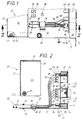
- the front end according to the invention initially consists of at least one L-shaped angled electrically conductive sheet 10, which has a front leg 11 and one piece therewith over the associated first fold edge 14 Base leg 12 forms. But the sheet is expedient 10, beyond this L-shape, angled overall in a U-shape, whereby, over a further folding edge 15, a cover leg parallel to the base leg 12 13 arises.
- the mutually facing inner surfaces 16, 17 of the Base and front legs 11, 12 are at least partially blank and generate electrically conductive contact surfaces, which are subsequently called "contact inner surfaces” should be named. In the present case, these extend Contact surfaces 16, 17 over the entire inner surfaces of the sheet 10, the Outer surfaces are only provided with a colored covering or the like.
- the front panel consists of a protective hood 20, which in Fig. 1 and 2 disassembled from the sheet 10 Condition is shown.
- the protective hood 20 also consists of a metallic, electrically conductive sheet metal, the various walls of which are bent Overlap and join, like welding, from a one-piece stamped sheet metal part are generated.
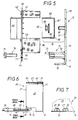
- the hood 20 comprises a spaced apart in the case of assembly to the front leg 11 extending hood rear wall 21, one opposite the base leg 12 spaced hood top wall 22 and two serving as both ends of the fully assembled front end Hood side walls 23. This is mainly due to the assembled position can be seen in Fig. 6.
- the top wall of the hood is over edge folds 24 22 connected to each of the two associated hood side walls 23.
- the base leg 12 is in the end region with from Fig. 1 and 6 visible upward-facing tab 18 provided on the Inside of the electrically conductive hood side wall 23 seated threaded bushings 25 are assigned.
- the fastening screws 19 elongated holes in the rag and are in the in the protective hood 20 threaded bushings 25 screwed.
- the cover leg 13 engages under the hood top wall in the case of assembly 22 the cover leg 13 and reaches into one of the best Fig. 2 apparent free gap 26 below the cover leg 13 a.
- the protective hood 20 forms with the angled plate 10 a self-contained cuboid box, all inside the box shields other components located on all sides electrically.
- the hood rear wall 21 is facing the base leg 12 Bottom edge provided with a bevy of edge outbreaks 27, the Perform various incoming cables 30 serve, one of which Pair shown in Figs. 1 and 2.
- Each of these cables 30 is in its end region freed from its outer jacket 31, whereby the one below it usual cable shield 32 is exposed.
- the one with the exposed one Cable shield 32 provided area of the cable 30 is by the aforementioned Edge breakouts 27 of the hood 20 inserted into the box interior.
- the cable shield 32 is finally removed.
- the cable also has a substantially longitudinal drain wire 34, which is formed bare and for continuous longitudinal contact the cable shield 32 is used.
- the base leg 12 is used to fix the cable 30 there are, in pairs for each cable 30, both an interception point 28 and an earth terminal 29 is provided.
- To form the interception point 28 is the base leg 12 in its outer edge zone with a family of provided in a row punched holes 35 which one from the Enclose sheet metal T-piece.
- This T-piece 36 is used for assembly by a fastening strap 37 encompassing the cables 30.
- the base leg 12 is in Spaced from the punched holes 35 with a series of holes 38, which are used to mount U-shaped clamps 39.
- the Clamping brackets 39 grip the cables 30 individually or in pairs, specifically at their areas provided with exposed cable shields 32. over the terminals 39, the cable shields 32 to the already mentioned inner contact surface 16 of the base leg 12 pressed.
- the base leg has cable shields 32 contacted in this way 12 also a grounding point 49 shown in FIG. 1, the from a welded-on set screw with nuts and contact washers consists.
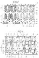
- FIG. 1, 2 and 5 An essential part of the front end is one from FIG. 1, 2 and 5 visible circuit board 40, the structure of which is shown in FIGS. 3 and 4 in more detail is shown.
- the circuit board 40 is at a parallel distance 78 to the contact inner surface 17 of the front leg 11 arranged and serves as a carrier of sockets 50 on the one hand and two types of connection blocks 60, 60 ' on the other hand.
- the sockets 50 are on the in the case of assembly Front leg 11 facing plate front 41, while the terminal blocks 60, 60 'are arranged on the back of the plate 42.
- the bushings 50 are at a distance of two 86 mutually parallel rows 51, 52 on the printed circuit board 40 attached, for which connected with earth tracks 44 and 46, at the same time the electrical Contacting of contact pins serving for grounding pins 55 are provided in the circuit board.
- the circuit board also has connection breakthroughs serving only to mechanically fix the socket 50 48.
- Each socket 50 is hatched in FIGS. 2 and 5 indicated outer shields 53 on which the grounding pins to sit. Pass through at least two of these grounding pins per socket 50 two contact openings 55 and are with the associated earth tracks 44, 46 connected.
- the terminal blocks 60 are like the rear view 42 of the circuit board 40 in FIG. 3, also arranged in two parallel rows 61, 62, which, however, as the side view of FIG. 2 teaches, is offset in height from one another are arranged.
- Terminal blocks 60 serve plate openings 59.
- the electrical Contacting takes place via separate contact openings 63 Pins of these blocks 60.
- These contact openings 63 are over 3 and 4 with further front and rear conductor tracks 43 according to FIGS contact openings 64 for connecting pins connected for the associated socket 50.
- the terminal blocks 60 are with Strips-free contacts 68, best seen in FIG. 3, are provided and serve to connect the already in connection with Fig. 1 and 2 described wires 33 of the incoming cable 30.
- each include a pair of identical terminal blocks 60, the field 65 marked 65 in FIG. 3 on both sides limit.
- the contact openings 63 for the pins of the terminal blocks 60 are identified in greater detail by printed numerals 1 to 8 in FIG. 3.
- All conductor tracks 43 are arranged in each of these fields 65, to such a connection block pair 60 on the one hand and the associated Socket 50 on the other hand belong.
- Such a field 65 is located corresponding to the number of sockets 50, in the height range of each of the two Terminal block rows 61 and 62.
- In the lower area of each Field 65, towards the lower plate edge 67, are the mentioned Contact openings 64 for the pins of the associated socket 50.
- Between adjacent fields 65 there are free zones 66, which of go through the upper to the lower plate edge 67.
- the connection blocks are located on both sides of this zone 66 60 two block pairs belonging to adjacent cables 30.
- FIG. 4 Front view 41 highlighted by dot hatching, whose location in the Rear view 42 in Fig. 3 is illustrated by dot outlines. That is part of it initially one essentially parallel to the lower longitudinal edge of the board 67 extending wide current-carrying strip 44, the following shortly called "ErdbahnstMail". Go from this, across it, a bevy of narrow strips 45 knot-like, which is why this below for short "earth railway branches" are to be called.
- These earth orbital branches are 45 again the starting point for one branched off from it, in contrast still narrower earth orbit 46, which is referred to as "earth orbit branch” should be designated.
- connection points 63, 64 belong together Terminal block pairs 60 and sockets 50 together with those in between running conductor tracks shielded against each other in fields, whereby the crosstalk attenuation of the front termination according to the invention is decisive is improved.
- the contact openings serving for the electrical contacting of contact pins 55 of the lower terminal block row 61 are in pairs integrated in the broad strip of earth 44.
- the corresponding contact breakthroughs 55 for the upper terminal block row 62 are in two copies in the local branch 46 and a third copy 55 arranged in the described earth orbit widening 47.
- the contact breakthroughs 55 for the individual sockets 50 form a first earth contact for the outer shield 53, which, as already mentioned, one assigned to each socket 50 and highlighted in FIG. 2 by dot hatching is.
- the invention also has a special second earth contact at 70, which will be described in more detail.
- terminal blocks 60 'already mentioned above the also has insulation-free cutting contacts, serves for connection of the bare cable wires 34 already mentioned, both arriving in pairs Cable 30, as best seen in FIGS. 1 and 2.
- For the electrical pins of these terminal blocks 60 'are contact openings 54 arranged in the area of the current-carrying earth track strip 44, such as 4 emerges. In this area, however, there are only mechanical ones Connection serving further breakthroughs 58 for each of these Terminal blocks 60 'are provided. All connection blocks used for the additional wire 34 60 'are, as shown in FIG. 3, in a common lower row 69 and are located in the plate edge 67 adjacent Edge zone.
- a bevy of these plate mounting holes 4 is located in the area of, as also the top view of FIG Earth orbit, namely the wide strip of earth orbit described above 44. How common is the one equipped with the conductor and earth tracks 43 to 46 Plate front and back 41, 42 with an insulating protective layer provided, but in the area of the aforementioned plate mounting hole 56 is a contact point 57 bare. This contact point is for distinction from a corresponding one located on the back of the plate 42 another contact point 77, hereinafter referred to as "front contact point" will. Accordingly, the rear contact point 77 becomes “back contact point” called.
- These front and rear contact points 57, 77 consist of the End faces of a contact ring penetrating the circuit board 40, the is electrically conductively connected to the earth track strip 44 and its Ring opening determines the plate mounting hole 56.
- the spacers 71 thus perform a triple task.
- the first task the threaded sleeves 71 consists, in the case of assembly, for the from FIG. 2 apparent defined distance 78 between the front leg 11 on the one hand and the assembled circuit board 40 on the other hand. this will determined by the length of the threaded sleeves 71.
- the socket 50 is a so-called modular jack trained and used for contacting plugs, not shown, which are provided with outgoing electrical cables.
- the second task of the spacers 71 is that with the components 50, 60, 60 'equipped circuit board 40 to attach to the front leg 11. This is ensured by the described thread engagement of the plate 40 penetrating fastening screws 74 in the internal thread 76 of the spacers 71.
- the electrically conductive spacers 71 meet third task of a good through connection between the earth orbits 44 to 47 of the printed circuit board 40 on the one hand and that via the base leg 12 grounded front leg 11 on the other hand.
- the front contact points described above 57 are in contact with the fastening screws 74 End faces 73 of the associated spacer 71.
- Outer shield 53 include special contact members 80 that are immediate are attached to the contact inner surface 17 of the front leg 11.
- These contact members 80 preferably comprise a U-profile and are expedient designed as a continuous U-profile rail.
- the U profile rail 80 is made of conductive material and is with its U-center bar 81 in case of installation in contact with the front leg 11.
- the nuts 84 press the middle rail 81 against the contact surface 17 of the front leg 11 on.
- the two U-side webs 82 of the rail come here 80 directly with the outer shield 83 of adjacent bushings 50 in touch.
- the U-rail 80 runs parallel to the lower one, which can also be seen in FIG. 5 Kink edge 14 of the sheet 10 and have a recognizable from FIG. 5 Rail width 85, which is greater than / equal to the height distance that can be seen in FIG. 2 86 between the two superimposed parallel rows 51, 52 of the sockets 50.
- the contact member instead of the one-piece U-rail 80 could the contact member also consist of individual contact clips, which if they are U-shaped, contact only one pair of adjacent sockets 50 at a time. In this case it could also be bushings 50, which are not are arranged in superimposed rows of sockets 51, 52, but lie side by side in a common row 51 or 52.
- the protective hood 20 extends from the front leg 11 and hers Hood rear wall 21 meets base leg 12 in zone 87, the, seen in the direction of the incoming cable 30, behind the Cable clamp 39 is.
- the hood rear wall 21 meets with its from Fig. 7 visible edge outbreaks 27 on the cable shield 32 in the clearance area between the cable clamp 39 and the assembled printed circuit board 40.
Landscapes
- Engineering & Computer Science (AREA)
- Microelectronics & Electronic Packaging (AREA)
- Physics & Mathematics (AREA)
- Electromagnetism (AREA)
- Power Engineering (AREA)
- Shielding Devices Or Components To Electric Or Magnetic Fields (AREA)
- Patch Boards (AREA)
- Casings For Electric Apparatus (AREA)
Claims (15)
- Fermeture frontale pour armoires électriques, boítiers, châssis ou assimilés,caractérisée en ce queformée d'une tôle (10) au moins coudée en L comportant une branche frontale (11) et une branche de base monobloc (12) allant au-delà de l'arête coudée (14),formée d'une carte à circuits imprimés (40) disposée essentiellement parallèle (78) derrière la branche frontale (11), laquelle (40) sert de support, sur son côté avant (41), à des prises (50) disposées en rangées parallèles (51, 52) et avec lesquelles (50) des fiches entrent en contact, et au dos (42) à des blocs de raccordement (60, 60'),lesquels (60) soit sont reliés aux prises (50) situées côté avant par des circuits imprimés (43) sur la carte (40) et servent au raccordement des divers fils (33) provenant des câbles arrivants (30),soit ils (60') sont reliés à des circuits de terre (44) situés sur la carte à circuits imprimés (40) et sont destinés chacun au raccordement des fils auxiliaires (34) connectés à la tresse de blindage (32) des câbles arrivants (30),les orifices frontaux (88) des prises (50) servant à connecter les fiches reposent dans des fenêtres (79) ménagées dans la branche frontale (11) et les prises présentent un blindage extérieur (53) relié aux circuits de terre (44, 46) des cartes à circuits imprimés (40),la branche de base (12) possède un point de jonction à la terre (49) et, pour chaque câble arrivant (30), présente aussi bien un point d'interception (28) qu'une bride de raccordement à la terre (29) du blindage (32) du câble,un élément de contact (80) de préférence à profilé en U (81, 82) est disposé dans l'espace (86) entre deux prises voisines (50) et en ce que les surfaces intérieures se faisant face des branches frontales et de base (11, 12) présentent des surfaces-contact intérieures (17, 16) au moins localement à nu, électroconductrices,l'élément-contact (80) applique par sa nervure médiane en U (81) contre la surface-contact intérieure (17) de la branche frontale (11) et touche directement, par ses nervures latérales en U (82), de manière électroconductrice, le blindage extérieur (53) des prises voisines (50),la carte carte à circuits imprimés (40) est reliée à la branche frontale (11) par des écarteurs électroconducteurs (71),l'écarteur (71) repose par une extrémité frontale (72) contre la surface-contact intérieure (17) de la branche frontale (11) et touche, par l'extrémité frontale opposée (73), un point-contact avant (57) situé sur le côté avant (41) de la carte à circuits imprimés,en ce que ce point-contact avant (57) fait partie intégrante du circuit de terre (44) équipant la carte à circuits imprimés (40), à laquelle sont aussi reliés les blocs de raccordement (60') des fils auxiliaires (34) des câbles,et en ce qu'un capot protecteur (20) électroconducteur ponte à une certaine distance la zone angulaire située entre les branches frontale et de base (11, 12), la paroi supérieure (22) du capot protecteur (20) dépasse la carte à circuits imprimés (40) garnie, protège latéralement, par ses parois latérales (23) aux deux extrémités, la carte à circuits imprimés (40) fixée à une certaine distance contre la branche frontale (11), et recouvre pas sa paroi arrière (21) les blocs de raccordement (60, 60') situés au dos (42).
- Fermeture frontale selon la revendication 1, caractérisée en ce que l'élément-contact se compose d'un rail continu profilé en U (80) fixé contre la branche avant (11) et qui a un tracé essentiellement parallèle à l'arête du coude (14) de la tôle (10) et dont la largeur (85) correspond à l'écart en hauteur (86) entre deux rangées parallèles (51, 52) de prises (50).
- Fermeture frontale selon la revendication 2, caractérisée en ce que la nervure médiane (81) du rail profilé en U (80) est traversée par des tiges filetées (83), en ce que les tiges filetées (83) sont fixées contre la surface-contact intérieure (17) de la branche frontale (11) et qu'elles servent à visser des écrous dessus (84) qui, lors du montage de la nervure médiane (81) viennent appliquer contre la surface-contact (17) de la branche frontale (11).
- Fermeture frontale selon l'une ou plusieurs des revendications 1 à 3, caractérisée en ce que les écarteurs sont formés par des douilles taraudées (71) fixées par une extrémité (72) contre la surface-contact (17) de la branche frontale (11) et servent à l'engrènement du filet (76) de vis de fixation (74) qui en cas de montage arrivent par le dos (42) de la carte à circuits imprimés (40) en traversant des trous de fixation de plaque (56).
- Fermeture frontale selon la revendication 4, caractérisée en ce que les points-contact avant (57) des écarteurs (71) ceinturent en forme d'anneau les trous (56) de fixation des plaques sur le côté avant (41) de la carte à circuits imprimés (40).
- Fermeture frontale selon la revendication 4 ou 5, caractérisée en ce que le trou de fixation des plaques (56) au dos (42) de la carte à circuits imprimés (40) est ceinturé par un point-contact dorsal (77) de préférence annulaire qui sert en cas de montage à ce qu'une vis de fixation (74) vienne appliquer dessus par sa tête (75).
- Fermeture frontale selon l'une ou plusieurs des revendications 1 à 6, caractérisée en ce que les circuits de terre équipant la carte à circuits imprimés (40) présentent une bande large pouvant transporter l'électricité (bande de jonction à la terre 44) et ayant un tracé parallèle à un bord (67) de la carte à circuits imprimés (40), en ce que cette bande de jonction à la terre (44) sert à fixer aussi bien les blocs de raccordement (60') dorsaux des fils auxiliaires (34) des câbles, qu'au moins en partie une rangée avant (61) de prises (60) et en ce que cette bande de jonction à la terre (44) supporte les points-contact avant (57) des écarteurs (71) ainsi que les points-contact dorsaux (77) destinés aux vis de fixation correspondantes (74).
- Fermeture frontale selon la revendication 7, caractérisée en ce que la bande large (44) de jonction à la terre présente, en cas de montage de la carte à circuits imprimés (40), un tracé parallèle à l'arête (14) du coude entre les branches frontale et de base (11, 12).
- Fermeture frontale selon l'une ou plusieurs des revendications 1 à 8, caractérisée en ce que les bandes de jonction à la terre (44 à 47) ceinturent au moins partiellement en forme de cadre les zones (65) de la carte (40) qui présentent des circuits imprimés (43) allant ensemble avec leurs points de branchement (63, 64) entre chaque prise (50) et les blocs de raccordement qui leur sont affectés (paire de blocs de branchement 60).
- Fermeture frontale selon la revendication 9, caractérisée en ce que les bandes de jonctions à la terre (44 à 47) ayant un tracé en forme de cadre forment un réseau de circuits en forme de coordonnées, lequel réseau se compose d'une part de la bande large de jonction à la terre (44) parallèle au bord de carte, et d'autre part d'un grand nombre de branches étroites (45) de la bande de jonction à la terre qui en partent, ces branches (45) circulant chacune dans la zone libre (66) entre deux prises situées dans une rangée (61 ou 62) ou voisines (50) (cf. la fig. 4).
- Fermeture frontale selon la revendication 10, caractérisée en ce que les branches (45) de la bande de jonction à la terre sont équipées d'autres ramifications étroites (46) dans la zone des prises (50) disposées en rangée décalée en hauteur (62) par rapport à la position du ruban de jonction à la terre (44) (cf. la fig. 4).
- Fermeture frontale selon la revendication 11, caractérisée en ce qu'aussi bien les branches (45) que les ramifications (46) ont certes un tracé essentiellement linéaire, mais qu'elles présentent dans leur zone de transition un élargissement de bande (47) créant des points de branchement supplémentaires (55) pour le blindage extérieur (53) (cf. la fig. 4).
- Fermeture frontale selon la revendication 1, caractérisée en ce que la paroi arrière (21) du capot protecteur (20) est disposée, en cas de montage contre la branche de base (12), dans la zone (87) située entre d'une part la carte à circuits imprimés (40) et d'autre part les bornes de raccordement à la terre (29) des tresses (32) blindant les câbles arrivants (30).
- Fermeture frontale selon l'une ou plusieurs des revendications 1 à 13, caractérisée en ce que la tôle (10) est coudée en U, qu'elle présente outre une branche frontale et de base (11, 12) déterminée par une première arête coudée (14), une branche couvrante (13) décalée en hauteur par une arête coudée (15) au tracé de préférence parallèle à la première arête coudée (14) et faisant face à la branche de base (12), laquelle branche (13) se situe au-dessus de la carte à circuits imprimés (40).
- Fermeture frontale selon la revendication 14, caractérisée en ce que la branche couvrante (13) dépasse, en cas de montage, la paroi supérieure (22) du capot de protection (20) et en ce que cette paroi supérieure (22) est disposée dans un espace libre (26) situé entre le bord supérieur de la carte à circuits imprimés (40) et la branche couvrante (13).
Applications Claiming Priority (2)
| Application Number | Priority Date | Filing Date | Title |
|---|---|---|---|
| DE4302876A DE4302876A1 (de) | 1993-02-02 | 1993-02-02 | Frontabschluß für elektrische Schränke, Gehäuse, Gestelle oder dergleichen |
| DE4302876 | 1993-02-02 |
Publications (3)
| Publication Number | Publication Date |
|---|---|
| EP0609552A2 EP0609552A2 (fr) | 1994-08-10 |
| EP0609552A3 EP0609552A3 (en) | 1996-01-17 |
| EP0609552B1 true EP0609552B1 (fr) | 1998-05-20 |
Family
ID=6479441
Family Applications (1)
| Application Number | Title | Priority Date | Filing Date |
|---|---|---|---|
| EP93120700A Expired - Lifetime EP0609552B1 (fr) | 1993-02-02 | 1993-12-23 | Fermeture frontale pour armoires électriques, supports châssis ou similaires |
Country Status (3)
| Country | Link |
|---|---|
| EP (1) | EP0609552B1 (fr) |
| AT (1) | ATE166496T1 (fr) |
| DE (2) | DE4302876A1 (fr) |
Cited By (1)
| Publication number | Priority date | Publication date | Assignee | Title |
|---|---|---|---|---|
| DE10236361C5 (de) * | 2002-08-08 | 2010-08-12 | Adc Gmbh | Verteileranschlußmodul für die Telekommunikations- und Datentechnik |
Families Citing this family (2)
| Publication number | Priority date | Publication date | Assignee | Title |
|---|---|---|---|---|
| DE19711102C2 (de) * | 1997-03-08 | 1998-12-17 | Krone Ag | Vorrichtung zur Potentialführung von geschirmten Kabeln in Verteilereinrichtungen der Telekommunikations- und Datentechnik |
| DE102009032172B4 (de) * | 2009-07-07 | 2012-09-27 | Schneider Electric Motion Deutschland Gmbh | Steuergerät für einen Elektromotor mit einer Zugentlastung für ein Motorkabel |
Family Cites Families (13)
| Publication number | Priority date | Publication date | Assignee | Title |
|---|---|---|---|---|
| GB1097831A (en) * | 1964-01-30 | 1968-01-03 | Rca Corp | Computer back plane wiring device |
| US3546539A (en) * | 1968-05-28 | 1970-12-08 | Texas Instruments Inc | Integrated circuit mounting panel |
| DE7422338U (de) * | 1973-07-03 | 1974-10-10 | Centre De Recherches Metallurgiques - Centrum Voor Resea | Schaltungsplatte fur Rechengeräte |
| DE2829515C2 (de) * | 1978-07-05 | 1983-04-28 | Licentia Patent-Verwaltungs-Gmbh, 6000 Frankfurt | Schaltungsplatte für Baugruppen von Geräten der Nachrichtentechnik |
| DE3402095A1 (de) * | 1984-01-21 | 1985-08-01 | Licentia Patent-Verwaltungs-Gmbh, 6000 Frankfurt | Einschub fuer steuer- und ueberwachungseinrichtungen |
| US4583808A (en) * | 1985-03-05 | 1986-04-22 | Ncr Corporation | Configurable multiple connector panel |
| DE3633052A1 (de) * | 1986-09-29 | 1988-04-07 | Thomas Klotz Musikelektronik G | Verknuepfungsvorrichtung fuer elektrische leiter sowie diesbezuegliche einschubeinheit |
| DE8707612U1 (de) * | 1987-05-27 | 1987-08-27 | Siemens AG, 1000 Berlin und 8000 München | Vorrichtung zum Kontaktieren der Schirmung von Verbindungsleitungen bei Geräten der Kommunikationstechnik |
| US4768961A (en) * | 1987-10-09 | 1988-09-06 | Switchcraft, Inc. | Jackfield with front removable jack modules having lamp assemblies |
| DE8716277U1 (de) * | 1987-12-09 | 1988-02-18 | Siemens AG, 1000 Berlin und 8000 München | Gestell für die elektrische Nachrichtentechnik |
| US5173845A (en) * | 1989-12-26 | 1992-12-22 | Star Technologies, Inc. | High density frontplane interconnection system |
| DE9109072U1 (de) * | 1991-07-23 | 1991-10-24 | Siemens AG, 8000 München | Gehäuse für ein Handfunksprechgerät |
| DE9202912U1 (de) * | 1992-03-05 | 1992-04-30 | Quante AG, 5600 Wuppertal | Elektrische Buchsen aufweisender Frontabschluß für elektrische Schränke, Gehäuse, Gestelle od. dgl. |
-
1993
- 1993-02-02 DE DE4302876A patent/DE4302876A1/de not_active Withdrawn
- 1993-12-23 DE DE59308580T patent/DE59308580D1/de not_active Expired - Fee Related
- 1993-12-23 AT AT93120700T patent/ATE166496T1/de not_active IP Right Cessation
- 1993-12-23 EP EP93120700A patent/EP0609552B1/fr not_active Expired - Lifetime
Cited By (1)
| Publication number | Priority date | Publication date | Assignee | Title |
|---|---|---|---|---|
| DE10236361C5 (de) * | 2002-08-08 | 2010-08-12 | Adc Gmbh | Verteileranschlußmodul für die Telekommunikations- und Datentechnik |
Also Published As
| Publication number | Publication date |
|---|---|
| ATE166496T1 (de) | 1998-06-15 |
| DE4302876A1 (de) | 1994-08-04 |
| DE59308580D1 (de) | 1998-06-25 |
| EP0609552A2 (fr) | 1994-08-10 |
| EP0609552A3 (en) | 1996-01-17 |
Similar Documents
| Publication | Publication Date | Title |
|---|---|---|
| DE4309039C2 (de) | Anschlußdose für abgeschirmte Kabel, insbesondere für Datenübertragungskabel | |
| DE69112658T2 (de) | Abgeschirmter Verbinder. | |
| DE3201142C2 (fr) | ||
| DE69501004T2 (de) | Verbindungsgehäuse für eine Mehrzahl von abgeschirmten Kabeln | |
| DE69331959T2 (de) | Abgeschirmter Verbinder für Datenübertragung | |
| DE3525012A1 (de) | Busleiste fuer die oberflaechenmontage | |
| DE8803544U1 (de) | Baugruppenträger mit abgeschirmten Steckbaugruppen | |
| DE3626800A1 (de) | Anordnung zum schutz vor ueberspannungen | |
| EP0456858B1 (fr) | Dispositif de mise à la terre | |
| EP0609552B1 (fr) | Fermeture frontale pour armoires électriques, supports châssis ou similaires | |
| EP0261474B1 (fr) | Fiche pour câble | |
| EP0097255A1 (fr) | Connecteur distributeur | |
| DE9202912U1 (de) | Elektrische Buchsen aufweisender Frontabschluß für elektrische Schränke, Gehäuse, Gestelle od. dgl. | |
| DE3634462A1 (de) | Mit profilschienen eines baugruppentraegers verbindbare halteschiene | |
| DE4440602C2 (de) | Einrichtung zum Sichern von elektrischen Leitungen | |
| EP1472766A1 (fr) | Dispositif de raccordement ou de distribution pour appareils electriques d'installation | |
| EP0658059A1 (fr) | Plaque à bornes de raccordement et déconnexion | |
| DE102019101859A1 (de) | Kontakt- und Busschienenanordnung, Elektronikgehäuseanordnung mit einer solchen Kontakt- und Busschienenanordnung, und Verfahren zur Entnahme eines Elektronikgehäuses aus einer solchen Elektronikgehäuseanordnung | |
| DE2740684C2 (de) | Elektrische Verbindung eines Schirmmantels eines Schaltkabels mit einem Baugruppenrahmen | |
| DE69633107T2 (de) | Abzweigdose mit Mitteln zur mechanischen Führung von Kabeln | |
| DE9411457U1 (de) | Elektrische Anschlußklemme | |
| AT409047B (de) | Vorrichtung zur erdung einer modular aufgebauten gehäuseeinheit | |
| EP0589307B1 (fr) | Support pour appareils comportant un rail avec fixation mécanique et contact électrique integral | |
| DE3878496T2 (de) | Steckverbinder fuer geschirmtes flachkabel. | |
| DE4331143C1 (de) | Anschlußdose zur Bildung einer Anschlußeinrichtung für ein Datennetz |
Legal Events
| Date | Code | Title | Description |
|---|---|---|---|
| PUAI | Public reference made under article 153(3) epc to a published international application that has entered the european phase |
Free format text: ORIGINAL CODE: 0009012 |
|
| AK | Designated contracting states |
Kind code of ref document: A2 Designated state(s): AT DE ES FR GB IT NL |
|
| PUAL | Search report despatched |
Free format text: ORIGINAL CODE: 0009013 |
|
| AK | Designated contracting states |
Kind code of ref document: A3 Designated state(s): AT DE ES FR GB IT NL |
|
| 17P | Request for examination filed |
Effective date: 19951216 |
|
| GRAG | Despatch of communication of intention to grant |
Free format text: ORIGINAL CODE: EPIDOS AGRA |
|
| GRAG | Despatch of communication of intention to grant |
Free format text: ORIGINAL CODE: EPIDOS AGRA |
|
| GRAH | Despatch of communication of intention to grant a patent |
Free format text: ORIGINAL CODE: EPIDOS IGRA |
|
| 17Q | First examination report despatched |
Effective date: 19971031 |
|
| GRAH | Despatch of communication of intention to grant a patent |
Free format text: ORIGINAL CODE: EPIDOS IGRA |
|
| GRAA | (expected) grant |
Free format text: ORIGINAL CODE: 0009210 |
|
| AK | Designated contracting states |
Kind code of ref document: B1 Designated state(s): AT DE ES FR GB IT NL |
|
| PG25 | Lapsed in a contracting state [announced via postgrant information from national office to epo] |
Ref country code: IT Free format text: LAPSE BECAUSE OF FAILURE TO SUBMIT A TRANSLATION OF THE DESCRIPTION OR TO PAY THE FEE WITHIN THE PRESCRIBED TIME-LIMIT;WARNING: LAPSES OF ITALIAN PATENTS WITH EFFECTIVE DATE BEFORE 2007 MAY HAVE OCCURRED AT ANY TIME BEFORE 2007. THE CORRECT EFFECTIVE DATE MAY BE DIFFERENT FROM THE ONE RECORDED. Effective date: 19980520 Ref country code: FR Free format text: LAPSE BECAUSE OF FAILURE TO SUBMIT A TRANSLATION OF THE DESCRIPTION OR TO PAY THE FEE WITHIN THE PRESCRIBED TIME-LIMIT Effective date: 19980520 Ref country code: ES Free format text: THE PATENT HAS BEEN ANNULLED BY A DECISION OF A NATIONAL AUTHORITY Effective date: 19980520 |
|
| REF | Corresponds to: |
Ref document number: 166496 Country of ref document: AT Date of ref document: 19980615 Kind code of ref document: T |
|
| GBT | Gb: translation of ep patent filed (gb section 77(6)(a)/1977) |
Effective date: 19980520 |
|
| REF | Corresponds to: |
Ref document number: 59308580 Country of ref document: DE Date of ref document: 19980625 |
|
| EN | Fr: translation not filed | ||
| PG25 | Lapsed in a contracting state [announced via postgrant information from national office to epo] |
Ref country code: GB Free format text: LAPSE BECAUSE OF NON-PAYMENT OF DUE FEES Effective date: 19981223 |
|
| PLBE | No opposition filed within time limit |
Free format text: ORIGINAL CODE: 0009261 |
|
| STAA | Information on the status of an ep patent application or granted ep patent |
Free format text: STATUS: NO OPPOSITION FILED WITHIN TIME LIMIT |
|
| 26N | No opposition filed | ||
| PG25 | Lapsed in a contracting state [announced via postgrant information from national office to epo] |
Ref country code: NL Free format text: LAPSE BECAUSE OF NON-PAYMENT OF DUE FEES Effective date: 19990701 |
|
| GBPC | Gb: european patent ceased through non-payment of renewal fee |
Effective date: 19981223 |
|
| NLV4 | Nl: lapsed or anulled due to non-payment of the annual fee |
Effective date: 19990701 |
|
| PGFP | Annual fee paid to national office [announced via postgrant information from national office to epo] |
Ref country code: AT Payment date: 20071204 Year of fee payment: 15 |
|
| PGFP | Annual fee paid to national office [announced via postgrant information from national office to epo] |
Ref country code: DE Payment date: 20090202 Year of fee payment: 16 |
|
| PG25 | Lapsed in a contracting state [announced via postgrant information from national office to epo] |
Ref country code: AT Free format text: LAPSE BECAUSE OF NON-PAYMENT OF DUE FEES Effective date: 20081223 |
|
| PG25 | Lapsed in a contracting state [announced via postgrant information from national office to epo] |
Ref country code: DE Free format text: LAPSE BECAUSE OF NON-PAYMENT OF DUE FEES Effective date: 20100701 |