EP0609552B1 - Front closure for electrical cabinets, cases, frames and the like - Google Patents
Front closure for electrical cabinets, cases, frames and the like Download PDFInfo
- Publication number
- EP0609552B1 EP0609552B1 EP93120700A EP93120700A EP0609552B1 EP 0609552 B1 EP0609552 B1 EP 0609552B1 EP 93120700 A EP93120700 A EP 93120700A EP 93120700 A EP93120700 A EP 93120700A EP 0609552 B1 EP0609552 B1 EP 0609552B1
- Authority
- EP
- European Patent Office
- Prior art keywords
- circuit board
- printed circuit
- limb
- earth
- contact
- Prior art date
- Legal status (The legal status is an assumption and is not a legal conclusion. Google has not performed a legal analysis and makes no representation as to the accuracy of the status listed.)
- Expired - Lifetime
Links
- 125000006850 spacer group Chemical group 0.000 claims abstract description 16
- 239000004020 conductor Substances 0.000 claims abstract description 10
- 230000001681 protective effect Effects 0.000 claims description 11
- 230000007704 transition Effects 0.000 claims description 2
- 238000012216 screening Methods 0.000 claims 6
- 230000000712 assembly Effects 0.000 claims 1
- 238000000429 assembly Methods 0.000 claims 1
- 230000008878 coupling Effects 0.000 claims 1
- 238000010168 coupling process Methods 0.000 claims 1
- 238000005859 coupling reaction Methods 0.000 claims 1
- 239000002184 metal Substances 0.000 abstract description 4
- 238000000926 separation method Methods 0.000 abstract 1
- 210000001364 upper extremity Anatomy 0.000 description 21
- 230000012447 hatching Effects 0.000 description 3
- 230000000149 penetrating effect Effects 0.000 description 2
- 238000003466 welding Methods 0.000 description 2
- 230000015572 biosynthetic process Effects 0.000 description 1
- 210000001061 forehead Anatomy 0.000 description 1
- 238000009434 installation Methods 0.000 description 1
- 239000011241 protective layer Substances 0.000 description 1
- 230000005855 radiation Effects 0.000 description 1
- 238000007142 ring opening reaction Methods 0.000 description 1
- 238000005476 soldering Methods 0.000 description 1
- 210000003462 vein Anatomy 0.000 description 1
Images
Classifications
-
- H—ELECTRICITY
- H05—ELECTRIC TECHNIQUES NOT OTHERWISE PROVIDED FOR
- H05K—PRINTED CIRCUITS; CASINGS OR CONSTRUCTIONAL DETAILS OF ELECTRIC APPARATUS; MANUFACTURE OF ASSEMBLAGES OF ELECTRICAL COMPONENTS
- H05K1/00—Printed circuits
- H05K1/02—Details
- H05K1/0213—Electrical arrangements not otherwise provided for
- H05K1/0216—Reduction of cross-talk, noise or electromagnetic interference
- H05K1/0218—Reduction of cross-talk, noise or electromagnetic interference by printed shielding conductors, ground planes or power plane
-
- H—ELECTRICITY
- H02—GENERATION; CONVERSION OR DISTRIBUTION OF ELECTRIC POWER
- H02B—BOARDS, SUBSTATIONS OR SWITCHING ARRANGEMENTS FOR THE SUPPLY OR DISTRIBUTION OF ELECTRIC POWER
- H02B1/00—Frameworks, boards, panels, desks, casings; Details of substations or switching arrangements
- H02B1/015—Boards, panels, desks; Parts thereof or accessories therefor
- H02B1/06—Boards, panels, desks; Parts thereof or accessories therefor having associated enclosures, e.g. for preventing access to live parts
-
- H—ELECTRICITY
- H05—ELECTRIC TECHNIQUES NOT OTHERWISE PROVIDED FOR
- H05K—PRINTED CIRCUITS; CASINGS OR CONSTRUCTIONAL DETAILS OF ELECTRIC APPARATUS; MANUFACTURE OF ASSEMBLAGES OF ELECTRICAL COMPONENTS
- H05K1/00—Printed circuits
- H05K1/02—Details
- H05K1/0213—Electrical arrangements not otherwise provided for
- H05K1/0215—Grounding of printed circuits by connection to external grounding means
-
- H—ELECTRICITY
- H05—ELECTRIC TECHNIQUES NOT OTHERWISE PROVIDED FOR
- H05K—PRINTED CIRCUITS; CASINGS OR CONSTRUCTIONAL DETAILS OF ELECTRIC APPARATUS; MANUFACTURE OF ASSEMBLAGES OF ELECTRICAL COMPONENTS
- H05K9/00—Screening of apparatus or components against electric or magnetic fields
- H05K9/0007—Casings
- H05K9/0018—Casings with provisions to reduce aperture leakages in walls, e.g. terminals, connectors, cables
Definitions
- the invention relates to a front end in the preamble of claim 1 specified type.
- the front end includes an electrical conductive sheet which is angled at least in an L-shape and, by the crease edge separated, a front leg and one with it forms one-piece base leg.
- a circuit board At a parallel distance from the front leg runs a circuit board, the front of the carrier from in parallel Rows arranged and is on the back as a carrier of Terminal blocks is used.
- the terminal blocks on the one hand and the associated Sockets, on the other hand, are connected to one another via conductor tracks.
- the Terminal blocks are used to connect the various wires of incoming Cable.
- the circuit boards also have earth orbits, on the one hand are contacted with external shields located on the sockets and on the other hand electrically via further connection blocks with cable double wires are connected. These two wires are for contacting the cable shield the incoming cable determined.
- the invention is based, an inexpensive, easy to assemble the task Front end of the type mentioned in the preamble of claim 1 to develop, which is characterized by optimal shielding. This is according to the invention by the characterizing part of claim 1 achieved measures, which have the following special meaning comes to.
- the outer shielding of the sockets is immediate thanks to a U-contact element with an inner contact surface of the front leg in electrical connection, which, as already mentioned, is made in one piece with the base leg is trained and at the same time in electrical connection with both the earthing point located there as well as the earthing terminal there stands for the cable shields.
- This means that all sockets are independent of the earth orbits on the circuit board, via the U-contact element in electrical Connection.
- the earth tracks of the circuit board through electrically conductive spacers with the contact inner surface of the Front leg in contact.
- the circuit board has on its front Front contact points where the front ends of the other on the front leg seated spacers come to rest.
- connection blocks for the two wires are arranged. This is also good for a low impedance Contacting of the two cable wires is ensured. All outer shields the sockets are at a common potential. The invention thus enables a low-impedance through-connection of the cable shield up to the outer shielding of the socket, from the coupled one Plug the outgoing cables are connected for their good Grounding is also taken care of.
- the protective hood is used to shield one Radio frequency radiation. It covers all elements that are not grounded.
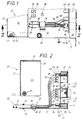
- the front end according to the invention initially consists of at least one L-shaped angled electrically conductive sheet 10, which has a front leg 11 and one piece therewith over the associated first fold edge 14 Base leg 12 forms. But the sheet is expedient 10, beyond this L-shape, angled overall in a U-shape, whereby, over a further folding edge 15, a cover leg parallel to the base leg 12 13 arises.
- the mutually facing inner surfaces 16, 17 of the Base and front legs 11, 12 are at least partially blank and generate electrically conductive contact surfaces, which are subsequently called "contact inner surfaces” should be named. In the present case, these extend Contact surfaces 16, 17 over the entire inner surfaces of the sheet 10, the Outer surfaces are only provided with a colored covering or the like.
- the front panel consists of a protective hood 20, which in Fig. 1 and 2 disassembled from the sheet 10 Condition is shown.
- the protective hood 20 also consists of a metallic, electrically conductive sheet metal, the various walls of which are bent Overlap and join, like welding, from a one-piece stamped sheet metal part are generated.
- the hood 20 comprises a spaced apart in the case of assembly to the front leg 11 extending hood rear wall 21, one opposite the base leg 12 spaced hood top wall 22 and two serving as both ends of the fully assembled front end Hood side walls 23. This is mainly due to the assembled position can be seen in Fig. 6.
- the top wall of the hood is over edge folds 24 22 connected to each of the two associated hood side walls 23.
- the base leg 12 is in the end region with from Fig. 1 and 6 visible upward-facing tab 18 provided on the Inside of the electrically conductive hood side wall 23 seated threaded bushings 25 are assigned.
- the fastening screws 19 elongated holes in the rag and are in the in the protective hood 20 threaded bushings 25 screwed.
- the cover leg 13 engages under the hood top wall in the case of assembly 22 the cover leg 13 and reaches into one of the best Fig. 2 apparent free gap 26 below the cover leg 13 a.
- the protective hood 20 forms with the angled plate 10 a self-contained cuboid box, all inside the box shields other components located on all sides electrically.
- the hood rear wall 21 is facing the base leg 12 Bottom edge provided with a bevy of edge outbreaks 27, the Perform various incoming cables 30 serve, one of which Pair shown in Figs. 1 and 2.
- Each of these cables 30 is in its end region freed from its outer jacket 31, whereby the one below it usual cable shield 32 is exposed.
- the one with the exposed one Cable shield 32 provided area of the cable 30 is by the aforementioned Edge breakouts 27 of the hood 20 inserted into the box interior.
- the cable shield 32 is finally removed.
- the cable also has a substantially longitudinal drain wire 34, which is formed bare and for continuous longitudinal contact the cable shield 32 is used.
- the base leg 12 is used to fix the cable 30 there are, in pairs for each cable 30, both an interception point 28 and an earth terminal 29 is provided.
- To form the interception point 28 is the base leg 12 in its outer edge zone with a family of provided in a row punched holes 35 which one from the Enclose sheet metal T-piece.
- This T-piece 36 is used for assembly by a fastening strap 37 encompassing the cables 30.
- the base leg 12 is in Spaced from the punched holes 35 with a series of holes 38, which are used to mount U-shaped clamps 39.
- the Clamping brackets 39 grip the cables 30 individually or in pairs, specifically at their areas provided with exposed cable shields 32. over the terminals 39, the cable shields 32 to the already mentioned inner contact surface 16 of the base leg 12 pressed.
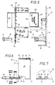
- the base leg has cable shields 32 contacted in this way 12 also a grounding point 49 shown in FIG. 1, the from a welded-on set screw with nuts and contact washers consists.
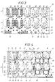
- FIG. 1, 2 and 5 An essential part of the front end is one from FIG. 1, 2 and 5 visible circuit board 40, the structure of which is shown in FIGS. 3 and 4 in more detail is shown.
- the circuit board 40 is at a parallel distance 78 to the contact inner surface 17 of the front leg 11 arranged and serves as a carrier of sockets 50 on the one hand and two types of connection blocks 60, 60 ' on the other hand.
- the sockets 50 are on the in the case of assembly Front leg 11 facing plate front 41, while the terminal blocks 60, 60 'are arranged on the back of the plate 42.
- the bushings 50 are at a distance of two 86 mutually parallel rows 51, 52 on the printed circuit board 40 attached, for which connected with earth tracks 44 and 46, at the same time the electrical Contacting of contact pins serving for grounding pins 55 are provided in the circuit board.
- the circuit board also has connection breakthroughs serving only to mechanically fix the socket 50 48.
- Each socket 50 is hatched in FIGS. 2 and 5 indicated outer shields 53 on which the grounding pins to sit. Pass through at least two of these grounding pins per socket 50 two contact openings 55 and are with the associated earth tracks 44, 46 connected.
- the terminal blocks 60 are like the rear view 42 of the circuit board 40 in FIG. 3, also arranged in two parallel rows 61, 62, which, however, as the side view of FIG. 2 teaches, is offset in height from one another are arranged.
- Terminal blocks 60 serve plate openings 59.
- the electrical Contacting takes place via separate contact openings 63 Pins of these blocks 60.
- These contact openings 63 are over 3 and 4 with further front and rear conductor tracks 43 according to FIGS contact openings 64 for connecting pins connected for the associated socket 50.
- the terminal blocks 60 are with Strips-free contacts 68, best seen in FIG. 3, are provided and serve to connect the already in connection with Fig. 1 and 2 described wires 33 of the incoming cable 30.
- each include a pair of identical terminal blocks 60, the field 65 marked 65 in FIG. 3 on both sides limit.
- the contact openings 63 for the pins of the terminal blocks 60 are identified in greater detail by printed numerals 1 to 8 in FIG. 3.
- All conductor tracks 43 are arranged in each of these fields 65, to such a connection block pair 60 on the one hand and the associated Socket 50 on the other hand belong.
- Such a field 65 is located corresponding to the number of sockets 50, in the height range of each of the two Terminal block rows 61 and 62.
- In the lower area of each Field 65, towards the lower plate edge 67, are the mentioned Contact openings 64 for the pins of the associated socket 50.
- Between adjacent fields 65 there are free zones 66, which of go through the upper to the lower plate edge 67.
- the connection blocks are located on both sides of this zone 66 60 two block pairs belonging to adjacent cables 30.
- FIG. 4 Front view 41 highlighted by dot hatching, whose location in the Rear view 42 in Fig. 3 is illustrated by dot outlines. That is part of it initially one essentially parallel to the lower longitudinal edge of the board 67 extending wide current-carrying strip 44, the following shortly called "ErdbahnstMail". Go from this, across it, a bevy of narrow strips 45 knot-like, which is why this below for short "earth railway branches" are to be called.
- These earth orbital branches are 45 again the starting point for one branched off from it, in contrast still narrower earth orbit 46, which is referred to as "earth orbit branch” should be designated.
- connection points 63, 64 belong together Terminal block pairs 60 and sockets 50 together with those in between running conductor tracks shielded against each other in fields, whereby the crosstalk attenuation of the front termination according to the invention is decisive is improved.
- the contact openings serving for the electrical contacting of contact pins 55 of the lower terminal block row 61 are in pairs integrated in the broad strip of earth 44.
- the corresponding contact breakthroughs 55 for the upper terminal block row 62 are in two copies in the local branch 46 and a third copy 55 arranged in the described earth orbit widening 47.
- the contact breakthroughs 55 for the individual sockets 50 form a first earth contact for the outer shield 53, which, as already mentioned, one assigned to each socket 50 and highlighted in FIG. 2 by dot hatching is.
- the invention also has a special second earth contact at 70, which will be described in more detail.
- terminal blocks 60 'already mentioned above the also has insulation-free cutting contacts, serves for connection of the bare cable wires 34 already mentioned, both arriving in pairs Cable 30, as best seen in FIGS. 1 and 2.
- For the electrical pins of these terminal blocks 60 'are contact openings 54 arranged in the area of the current-carrying earth track strip 44, such as 4 emerges. In this area, however, there are only mechanical ones Connection serving further breakthroughs 58 for each of these Terminal blocks 60 'are provided. All connection blocks used for the additional wire 34 60 'are, as shown in FIG. 3, in a common lower row 69 and are located in the plate edge 67 adjacent Edge zone.
- a bevy of these plate mounting holes 4 is located in the area of, as also the top view of FIG Earth orbit, namely the wide strip of earth orbit described above 44. How common is the one equipped with the conductor and earth tracks 43 to 46 Plate front and back 41, 42 with an insulating protective layer provided, but in the area of the aforementioned plate mounting hole 56 is a contact point 57 bare. This contact point is for distinction from a corresponding one located on the back of the plate 42 another contact point 77, hereinafter referred to as "front contact point" will. Accordingly, the rear contact point 77 becomes “back contact point” called.
- These front and rear contact points 57, 77 consist of the End faces of a contact ring penetrating the circuit board 40, the is electrically conductively connected to the earth track strip 44 and its Ring opening determines the plate mounting hole 56.
- the spacers 71 thus perform a triple task.
- the first task the threaded sleeves 71 consists, in the case of assembly, for the from FIG. 2 apparent defined distance 78 between the front leg 11 on the one hand and the assembled circuit board 40 on the other hand. this will determined by the length of the threaded sleeves 71.
- the socket 50 is a so-called modular jack trained and used for contacting plugs, not shown, which are provided with outgoing electrical cables.
- the second task of the spacers 71 is that with the components 50, 60, 60 'equipped circuit board 40 to attach to the front leg 11. This is ensured by the described thread engagement of the plate 40 penetrating fastening screws 74 in the internal thread 76 of the spacers 71.
- the electrically conductive spacers 71 meet third task of a good through connection between the earth orbits 44 to 47 of the printed circuit board 40 on the one hand and that via the base leg 12 grounded front leg 11 on the other hand.
- the front contact points described above 57 are in contact with the fastening screws 74 End faces 73 of the associated spacer 71.
- Outer shield 53 include special contact members 80 that are immediate are attached to the contact inner surface 17 of the front leg 11.
- These contact members 80 preferably comprise a U-profile and are expedient designed as a continuous U-profile rail.
- the U profile rail 80 is made of conductive material and is with its U-center bar 81 in case of installation in contact with the front leg 11.
- the nuts 84 press the middle rail 81 against the contact surface 17 of the front leg 11 on.
- the two U-side webs 82 of the rail come here 80 directly with the outer shield 83 of adjacent bushings 50 in touch.
- the U-rail 80 runs parallel to the lower one, which can also be seen in FIG. 5 Kink edge 14 of the sheet 10 and have a recognizable from FIG. 5 Rail width 85, which is greater than / equal to the height distance that can be seen in FIG. 2 86 between the two superimposed parallel rows 51, 52 of the sockets 50.
- the contact member instead of the one-piece U-rail 80 could the contact member also consist of individual contact clips, which if they are U-shaped, contact only one pair of adjacent sockets 50 at a time. In this case it could also be bushings 50, which are not are arranged in superimposed rows of sockets 51, 52, but lie side by side in a common row 51 or 52.
- the protective hood 20 extends from the front leg 11 and hers Hood rear wall 21 meets base leg 12 in zone 87, the, seen in the direction of the incoming cable 30, behind the Cable clamp 39 is.
- the hood rear wall 21 meets with its from Fig. 7 visible edge outbreaks 27 on the cable shield 32 in the clearance area between the cable clamp 39 and the assembled printed circuit board 40.
Landscapes
- Engineering & Computer Science (AREA)
- Microelectronics & Electronic Packaging (AREA)
- Physics & Mathematics (AREA)
- Electromagnetism (AREA)
- Power Engineering (AREA)
- Shielding Devices Or Components To Electric Or Magnetic Fields (AREA)
- Patch Boards (AREA)
- Casings For Electric Apparatus (AREA)
Abstract
Description
Die Erfindung bezieht sich auf einen Frontabschluß der im Oberbegriff des Anspruches 1 angegebenen Art. Der Frontabschluß umfaßt ein elektrisch leitendes Blech, welches zumindest L-förmig abgewinkelt ist und, durch die Knickkante voneinander getrennt, einen Frontschenkel und einen damit einstückigen Basisschenkel bildet. In Parallelabstand zum Frontschenkel verläuft eine Leiterplatte, die vorderseitig Träger von in kantenparallelen Reihen angeordneten Buchsen ist und rückseitig zugleich als Träger von Anschlußblöcken dient. Die Anschlußblöcke einerseits und die zugehörigen Buchsen andererseits sind über Leiterbahnen miteinander verbunden. Die Anschlußblöcke dienen zum Anschluß der diversen Adern von ankommenden Kabeln. Die Leiterplatten besitzen aber auch Erdbahnen, die einerseits mit an den Buchsen befindlichen Außenabschirmungen kontaktiert sind und andererseits über weitere Anschlußblöcke mit Kabel-Beidrähten elektrisch verbunden sind. Diese Beidrähte sind zur Kontaktierung des Kabelschirms der ankommenden Kabel bestimmt.The invention relates to a front end in the preamble of claim 1 specified type. The front end includes an electrical conductive sheet which is angled at least in an L-shape and, by the crease edge separated, a front leg and one with it forms one-piece base leg. At a parallel distance from the front leg runs a circuit board, the front of the carrier from in parallel Rows arranged and is on the back as a carrier of Terminal blocks is used. The terminal blocks on the one hand and the associated Sockets, on the other hand, are connected to one another via conductor tracks. The Terminal blocks are used to connect the various wires of incoming Cable. The circuit boards also have earth orbits, on the one hand are contacted with external shields located on the sockets and on the other hand electrically via further connection blocks with cable double wires are connected. These two wires are for contacting the cable shield the incoming cable determined.
Bei dem bekannten Frontabschluß dieser Art ist bereits die mechanische Befestigung der Buchsen von ihrer elektrischen Kontaktierung getrennt. Die Befestigung erfolgt über die Leiterplatte. Der bekannte Frontabschluß besitzt des Blech abgewinkelte Lappen, die zur Schraubbefestigung der Leiterplatte dienen. Die Erdbahnen verbinden den mit dem Kabel-Beidraht versehenen Kontaktblock mit der zugehörigen Außenabschirmung der Buchse, was zu einer hohen Impedanz führt. Die äußere Abschirmung der Buchsen ist unzureichend. Im Gebrauchsfall können unterschiedliche Potentiale entstehen.In the known front end of this type is already the mechanical Fastening of the sockets separated from their electrical contacts. It is attached via the circuit board. The well-known front end The sheet has angled tabs that are used to screw the Serve circuit board. The earth tracks connect it to the cable drain wire provided contact block with the corresponding outer shielding of the socket, which leads to high impedance. The outer shielding of the sockets is insufficient. In case of use, different Potentials arise.
Der Erfindung liegt die Aufgabe zugrunde, einen preiswerten, leicht montierbaren Frontabschluß der im Oberbegriff des Anspruches 1 genannten Art zu entwickeln, der sich durch eine optimale Abschirmung auszeichnet. Dies wird erfindungsgemäß durch die im Kennzeichen des Anspruches 1 angeführten Maßnahmen erreicht, denen folgende besondere Bedeutung zukommt.The invention is based, an inexpensive, easy to assemble the task Front end of the type mentioned in the preamble of claim 1 to develop, which is characterized by optimal shielding. This is according to the invention by the characterizing part of claim 1 achieved measures, which have the following special meaning comes to.
Durch ein U-Kontaktglied ist die äußere Abschirmung der Buchsen unmittelbar mit einer Kontaktinnenfläche des Frontschenkels in elektrischer Verbindung, der, wie bereits erwähnt wurde, einstückig mit dem Basisschenkel ausgebildet ist und zugleich auch in elektrischer Verbindung sowohl mit dem dort befindlichen Erdungspunkt als auch mit der dortigen Erdungsklemme für die Kabelschirme steht. Damit sind alle Buchsen, unabhängig von den Erdbahnen auf der Leiterplatte, über das U-Kontaktglied in elektrischer Verbindung. Darüber hinaus sind aber auch die Erdbahnen der Leiterplatte durch elektrisch leitende Abstandhalter mit der Kontaktinnenfläche des Frontschenkels in Kontakt. Dazu besitzt die Leiterplatte an ihrer Vorderseite Vorderkontaktstellen, an denen die Stirnenden der anderendig am Frontschenkel sitzenden Abstandhalter zu liegen kommen. Vorteilhaft ist es, dabei jene Erdbahnen für diese Vorderkontaktstellen zu verwenden, bei denen auf der Rückseite der Leiterplatte die Anschlußblöcke für die Kabel-Beidrähte angeordnet sind. Dadurch ist auch für eine gute niederohmige Kontaktierung der Kabel-Beidrähte untereinander gesorgt. Alle Außenabschirmungen der Buchsen befinden sich auf einem gemeinsamen Potential. Damit ermöglicht die Erfindung eine niederimpedante Durchverbindung des Kabelschirms bis zur Außenabschirmung der Buchse, von der über eingekuppelte Stecker die abgehenden Kabel angeschlossen sind, für deren gute Erdung zugleich gesorgt ist. Die Schutzhaube dient zur Abschirmung einer Hochfrequenzabstrahlung. Sie deckt alle nicht geerdeten Elemente ab.The outer shielding of the sockets is immediate thanks to a U-contact element with an inner contact surface of the front leg in electrical connection, which, as already mentioned, is made in one piece with the base leg is trained and at the same time in electrical connection with both the earthing point located there as well as the earthing terminal there stands for the cable shields. This means that all sockets are independent of the earth orbits on the circuit board, via the U-contact element in electrical Connection. In addition, however, are the earth tracks of the circuit board through electrically conductive spacers with the contact inner surface of the Front leg in contact. For this purpose, the circuit board has on its front Front contact points where the front ends of the other on the front leg seated spacers come to rest. It is advantageous to be there to use those earth orbits for these front contact points where on the back of the circuit board, the connection blocks for the two wires are arranged. This is also good for a low impedance Contacting of the two cable wires is ensured. All outer shields the sockets are at a common potential. The invention thus enables a low-impedance through-connection of the cable shield up to the outer shielding of the socket, from the coupled one Plug the outgoing cables are connected for their good Grounding is also taken care of. The protective hood is used to shield one Radio frequency radiation. It covers all elements that are not grounded.
Weitere Maßnahmen und Vorteile der Erfindung ergeben sich aus den Unteransprüchen, der nachfolgenden Beschreibung und den Zeichnungen. In den Zeichnungen ist die Erfindung in einem Ausführungsbeispiel dargestellt. Es zeigen:
- Fig. 1
- die Draufsicht auf den Endbereich eines nach der Erfindung gestalteten Frontabschlusses aus zwei noch nicht aneinander befestigten Bestandteilen, von denen einer bereichsweise ausgebrochen ist,
- Fig. 2
- eine geschnittene Seitenansicht durch den Frontabschluß von Fig. 1 längs der dortigen Schnittlinie II-II,
- Fig. 3 und 4
- die Vorderansicht bzw. Rückansicht auf ein Teilstück einer zum Frontabschluß von Fig. 1 und 2 gehörenden Leiterplatte, die bereichsweise mit und bereichsweise ohne daran angeschlossene Bauelemente gezeigt ist,
- Fig. 5
- in Vergrößerung und Explosionsdarstellung in einem der Fig. 2 entsprechenden Schnitt ein Teilstück der Leiterplatte mit zugehörigen weiteren Elementen des Frontabschlusses,
- Fig. 6,
- teilweise im Ausbruch, die Seitenansicht auf einen fertig aus beiden Bestandteilen montierten Frontabschluß und
- Fig. 7
- die Rückansicht eines Teilstücks des fertig montierten Frontabschlusses längs der in Fig. 6 erkennbaren Schnittlinie VII-VII.
- Fig. 1
- the top view of the end region of a front end designed according to the invention from two components which have not yet been fastened to one another, one of which has broken out in regions,
- Fig. 2
- 2 shows a sectional side view through the front end of FIG. 1 along the section line II-II there,
- 3 and 4
- 1 and 2, which is shown in some areas with and in some areas without components connected to it,
- Fig. 5
- 2 shows a section of the printed circuit board with associated further elements of the front end in an enlarged and exploded view in a section corresponding to FIG. 2,
- Fig. 6
- partly in the outbreak, the side view of a front cover and assembled from both components
- Fig. 7
- the rear view of a portion of the fully assembled front end along the line VII-VII shown in Fig. 6.
Der Frontabschluß nach der Erfindung besteht zunächst aus einem wenigstens
L-förmig abgewinkelten elektrisch leitenden Blech 10, welches einen Frontschenkel
11 und einen über die zugehörige erste Knickkante 14 damit einstückigen
Basisschenkel 12 bildet. Zweckmäßigerweise ist aber das Blech
10, über diese L-Form hinaus, insgesamt U-förmig abgewinkelt, wodurch,
über eine weitere Knickkante 15, ein zum Basisschenkel 12 paralleler Deckschenkel
13 entsteht. Die einander zugekehrten Innenflächen 16, 17 des
Basis- und Frontschenkels 11, 12 sind wenigstens bereichsweise blank und
erzeugen elektrisch leitende Kontaktflächen, die nachfolgend "Kontaktinnenflächen"
benannt werden sollen. Im vorliegenden Fall erstrecken sich diese
Kontaktflächen 16, 17 über die gesamten Innenflächen des Blechs 10, dessen
Außenflächen lediglich mit einem Farbbelag od. dgl. versehen sind.The front end according to the invention initially consists of at least one
L-shaped angled electrically
Ein weiterer Bestandteil der erfindungsgemäßen Frontplatte besteht aus
einer Schutzhaube 20, die in Fig. 1 und 2 in vom Blech 10 demontierten
Zustand gezeigt ist. Die Schutzhaube 20 besteht ebenfalls aus einem metallischen,
elektrisch leitenden Blech, dessen diverse Wände durch Abkanten,
Überlappen und Verbinden, wie Schweißen, aus einem einstückigen Blechstanzteil
erzeugt sind. Die Haube 20 umfaßt eine im Montagefall im Abstand
zum Frontschenkel 11 verlaufende Haubenhinterwand 21, eine gegenüber
dem Basisschenkel 12 beabstandete Haubenoberwand 22 und zwei
als beidendige Begrenzungen des fertig montierten Frontabschlusses dienenden
Haubenseitenwänden 23. Das ist vor allem aus der montierten Lage
in Fig. 6 zu erkennen. Über Randabkantungen 24 wird die Haubenoberwand
22 mit jeder der beiden zugehörigen Haubenseitenwände 23 verbunden.
Außerdem ist der Basisschenkel 12 im Endbereich mit aus Fig. 1 und
6 ersichtlichen nach oben weisenden Lappen 18 versehen, denen an der
Innenseite der elektrisch leitenden Haubenseitenwand 23 sitzende Gewindebüchsen
25 zugeordnet sind. Im Montagefall durchgreifen Befestigungsschrauben
19 in den Lappen befindliche Langlöcher und sind in den in der Schutzhaube
20 befindlichen Gewindebüchsen 25 einschraubbar. Wie aus dem Ausbruch
in Fig. 6 erkennbar ist, untergreift im Montagefall die Haubenoberwand
22 den Deckschenkel 13 und greift dabei in eine am besten aus
Fig. 2 ersichtliche freie Lücke 26 unterhalb des Deckschenkels 13 ein.
Im Montagefall bildet die Schutzhaube 20 mit dem abgewinkelten Blech
10 einen in sich geschlossenen quaderförmigen Kasten, der alle im Kasteninneren
befindlichen weiteren Bauteile allseitig elektrisch abschirmt.Another component of the front panel according to the invention consists of
a
Die Haubenhinterwand 21 ist an ihrer dem Basisschenkel 12 zugekehrten
Unterkante mit einer Schar von Randausbrüchen 27 versehen, die zum
Durchführen von diversen ankommenden Kabeln 30 dienen, von denen ein
Paar in Fig. 1 und 2 gezeigt ist. Jedes dieser Kabel 30 ist in seinem Endbereich
von seinem Außenmantel 31 befreit, wodurch zunächst der darunter
befindliche übliche Kabelschirm 32 freigelegt ist. Der mit dem freiliegenden
Kabelschirm 32 versehene Bereich des Kabels 30 ist durch die vorerwähnten
Randausbrüche 27 der Haube 20 ins Kasteninnere eingeführt. Im äußersten
Endbereich des Kabels 30, das sich im Montagefall im Kasteninneren befindet,
ist schließlich auch der Kabelschirm 32 entfernt. Dort liegen die einzelnen
Adern 33 des Kabels 30 für ihre weitere noch näher zu beschreibende
Kontaktierung frei. Außer diesen miteinander verseilten Adern 33 besitzt
das Kabel aber auch noch einen im wesentlichen längsverlaufenden Beidraht
34, der blank ausgebildet ist und zur durchgehenden Längskontaktierung
des Kabelschirms 32 dient.The hood
Zur Festlegung des Kabels 30 dient zunächst der Basisschenkel 12. Dort
sind, paarweise für jedes Kabel 30, sowohl eine Abfangstelle 28 als auch
eine Erdungsklemme 29 vorgesehen. Zur Ausbildung der Abfangstelle 28
ist der Basisschenkel 12 in seiner äußeren Randzone mit einer Schar von
in einer Reihe angeordneten Ausstanzungen 35 versehen, die ein aus dem
Blech gebildetes T-Stück umschließen. Dieses T-Stück 36 wird im Montagefall
von einem die Kabel 30 umgreifenden Befestigungsband 37 umgriffen.The
Für die Ausbildung der Erdungsklemmen 29 ist der Basisschenkel 12, in
Abstand zu den Ausstanzungen 35 mit einer Reihe von Löchern 38 versehen,
die jeweils zur Montage von U-förmigen Klemmbügeln 39 dienen. Die
Klemmbügel 39 umgreifen einzeln oder paarweise die Kabel 30, und zwar
an ihren mit freiliegenden Kabelschirmen 32 versehenen Bereichen. Über
die Klemmen 39 werden die Kabelschirme 32 an die bereits erwähnte Kontaktinnenfläche
16 des Basisschenkels 12 angedrückt. Für eine Erdung sämtlicher,
auf diese Weise kontaktierter Kabelschirme 32 besitzt der Basisschenkel
12 auch noch einen aus Fig. 1 ersichtlichen Erdungspunkt 49, der
aus einem aufgeschweißten Gewindestift mit Muttern und Kontaktscheiben
besteht.For the formation of the grounding clamps 29, the
Ein wesentlicher Bestandteil des Frontabschlusses ist eine aus Fig. 1,
2 und 5 ersichtliche Leiterplatte 40, deren Aufbau in Fig. 3 und 4 näher
gezeigt ist. Die Leiterplatte 40 ist in parallelem Abstand 78 zu der Kontaktinnenfläche
17 des Frontschenkels 11 angeordnet und dient als Träger
von Buchsen 50 einerseits und zwei Sorten von Anschlußblöcken 60, 60'
andererseits. Die Buchsen 50 befinden sich auf der im Montagefall dem
Frontschenkel 11 zugekehrten Plattenvorderseite 41, während die Anschlußblöcke
60, 60' auf der Plattenrückseite 42 angeordnet sind. Wie am besten
aus Fig. 4 zu entnehmen ist, sind die Buchsen 50 in zwei in Abstand
86 zueinander liegenden parallelen Reihen 51, 52 an der Leiterplatte 40
befestigt, wofür mit Erdbahnen 44 bzw. 46 verbundene, zugleich der elektrischen
Kontaktierung von Erdungsstiften dienende Kontaktdurchbrüche 55
in der Leiterplatte vorgesehen sind. Die Leiterplatte besitzt aber auch
lediglich zur mechanischen Festlegung der Buchse 50 dienende Verbindungsdurchbrüche
48. Jede Buchse 50 ist mit in Fig. 2 und 5 punktschraffiert
angedeuteten Außenabschirmungen 53 versehen, an denen die Erdungsstifte
sitzen. Mindestens zwei dieser Erdungsstifte pro Buchse 50 durchgreifen
zwei Kontaktdurchbrüche 55 und sind mit den zugehörigen Erdbahnen 44,
46 verbunden.An essential part of the front end is one from FIG. 1,
2 and 5
Auch die Anschlußblöcke 60 sind, wie die Rückansicht 42 der Leiterplatte
40 in Fig. 3 zeigt, auch in zwei parallelen Reihen 61, 62 angeordnet,
die aber, wie die Seitenansicht von Fig. 2 lehrt, im Höhenversatz zueinander
angeordnet sind. Für die mechanische Anbringung der aus Kunststoff bestehenden
Anschlußblöcke 60 dienen Plattendurchbrüche 59. Die elektrische
Kontaktierung erfolgt über gesonderte Kontaktdurchbrüche 63 durchgreifende
Anschlußstifte dieser Blöcke 60. Diese Kontaktdurchbrüche 63 sind über
vorder- und rückseitige Leiterbahnen 43 gemäß Fig. 3 und 4 mit weiteren
zur Durchführung von Anschlußstiften dienenden Kontaktdurchbrüchen 64
für die zugehörige Buchse 50 verbunden. Die Anschlußblöcke 60 sind mit
abisolierfreien, am besten aus Fig. 3 erkennbaren, Kontakten 68 versehen
und dienen zum Anschluß der bereits im Zusammenhang mit Fig. 1 und
2 beschriebenen Adern 33 des ankommenden Kabels 30. Zu den acht Adern
eines solchen Kabels 30 gehören jeweils ein Paar gleichartiger Anschlußblöcke
60, die ein in Fig. 3 mit 65 gekennzeichnetes Feld 65 beidseitig
begrenzen. Die Kontaktdurchbrüche 63 für die Anschlußstifte der Anschlußblöcke
60 sind durch aufgedruckte Ziffern 1 bis 8 in Fig. 3 näher gekennzeichnet.
In jedem dieser Felder 65 sind sämtliche Leiterbahnen 43 angeordnet,
die zu einem solchen Anschlußblock-Paar 60 einerseits und der zugehörigen
Buchse 50 andererseits gehören. Ein solches Feld 65 befindet sich,
entsprechend der Anzahl der Buchsen 50, im Höhenbereich jeder der beiden
Anschlußblock-Reihen 61 bzw. 62. Im unteren Bereich eines jeden
Feldes 65, zur unteren Plattenkante 67 hin, befinden sich die erwähnten
Kontaktdurchbrüche 64 für die Anschlußstifte der zugehörigen Buchse
50. Zwischen benachbarten Feldern 65 liegen freie Zonen 66, die von
der oberen bis zur unteren Plattenkante 67 durchgehen. Auf der Plattenrückseite
42 befinden sich beidseitig dieser Zone 66 jeweils die Anschlußblöcke
60 zweier, zu benachbarten Kabeln 30 gehörenden Blockpaare.The terminal blocks 60 are like the
Alle Erdbahnen der Leiterplatte 40 sind in der aus Fig. 4 ersichtlichen
Vorderansicht 41 durch Punktschraffur hervorgehoben, deren Lage in der
Rückansicht 42 in Fig. 3 durch Punktumrisse verdeutlicht ist. Dazu gehört
zunächst ein im wesentlichen parallel zur unteren Plattenlängskante
67 verlaufender breiter stromtragfähiger Streifen 44, der nachfolgend
kurz "Erdbahnstreifen" benannt werden soll. Von diesem gehen, quer dazu,
eine Schar von schmalen Streifen 45 astartig ab, weshalb diese nachfolgend
kurz "Erdbahnäste" bezeichnet werden sollen. Diese Erdbahnäste 45 sind
wiederum Ausgangspunkt für eine davon abgezweigte, demgegenüber noch
schmaler ausgebildete Erdbahn 46, die nachfolgend sinngemäß als "Erdbahnzweig"
bezeichnet werden soll. Im Übergangsbereich zwischen einem Erdbahnast
45 und einem Erdbahnzweig 46 befindet sich eine Verbreiterung
47 der Erdbahn. Diese im wesentlichen rechtwinkelig zueinander verlaufenden
Erdbahnzweige 46, Erdbahnäste 45 und der gemeinsame breite Erdbahnstreifen
44 erzeugen in der Leiterplatte 40 ein koordinatenförmiges Netz von
Erdbahnen, welches die zu der unteren Buchsen-Reihe 51 gehörende untere
Reihe von Feldern 65 der einzelnen zusammengehörigen Leiterbahnen
43 feldweise nahezu vollständig rahmenartig umschließt. Aber auch die
obere Reihe von Feldern 65, die zu den einzelnen Buchsen 50 der oberen
Buchsen-Reihe 52 gehören, sind dreiseitig rahmenartig von einem benachbarten
Paar von Erdbahnästen 45 einerseits und einem zwischen diesen verlaufenden
Erdbahnzweig 46 andererseits umgrenzt. Auf der zunächst freien
oberen Seite liegt aber im Montagefall, gemäß Fig. 2, der Deckschenkel
13 des Blechs 10. Damit sind alle Anschlußstellen 63, 64 zusammengehöriger
Anschlußblock-Paare 60 und Buchsen 50 zusammen mit den dazwischen
verlaufenden Leiterbahnen feldweise gegeneinander abgeschirmt, wodurch
die Nebensprechdämpfung des erfindungsgemäßen Frontabschlusses maßgeblich
verbessert ist.All earth tracks of the
Die zur elektrischen Kontaktierung von Kontaktstiften dienenden Kontaktdurchbrüche
55 der unteren Anschlußblock-Reihe 61 sind jeweils paarweise
in den breiten Erdbahnstreifen 44 integriert. Die entsprechenden Kontaktdurchbrüche
55 für die obere Anschlußblock-Reihe 62 sind in zwei Exemplaren
in dem dortigen Erdbahnzweig 46 und einem dritten Exemplar 55
in der beschriebenen Erdbahn-Verbreiterung 47 angeordnet. Die Kontaktdurchbrüche
55 für die einzelnen Buchsen 50 bilden eine erste Erdkontaktierung
für die Außenabschirmung 53, die, wie bereits erwähnt wurde, einer
jeden Buchse 50 zugeordnet und in Fig. 2 durch Punktschraffur hervorgehoben
ist. Die Erfindung besitzt aber noch eine besondere zweite Erdkontaktierung
bei 70, die noch näher beschrieben werden soll. The contact openings serving for the electrical contacting of contact pins
55 of the lower
Die bereits oben erwähnte andere Sorte von Anschlußblöcken 60', die
an sich auch abisolierfreie Schneidkontakte aufweist, dient zum Anschluß
der bereits erwähnten blanken Kabel-Beidrähte 34 beider paarweise ankommenden
Kabel 30, wie am besten aus Fig. 1 und 2 zu erkennen ist. Für
die elektrischen Stifte dieser Anschlußblöcke 60' sind Kontaktdurchbrüche
54 im Bereich des stromtragfähigen Erdbahnstreifens 44 angeordnet, wie
aus Fig. 4 hervorgeht. In diesem Bereich sind aber auch lediglich der mechanischen
Verbindung dienende weitere Durchbrüche 58 für jeden dieser
Anschlußblöcke 60' vorgesehen. Alle für den Beidraht 34 dienenden Anschlußblöcke
60' sind, ausweislich der Fig. 3, in einer gemeinsamen unteren Reihe
69 angeordnet und befinden sich in der der Plattenunterkante 67 benachbarten
Randzone.The other type of terminal blocks 60 'already mentioned above, the
also has insulation-free cutting contacts, serves for connection
of the
Eine solche vorderseitig mit Buchsen 50 und rückseitig mit Anschlußblöcken
60 und 60' ausgerüstete, vormontierte Leiterplatte 40 wird nun, wie anhand
der Fig. 5 näher erläutert wird, auf besondere Weise an dem Frontschenkel
11 befestigt. Dazu dienen aus leitendem Material bestehende
Abstandhalter 71, die im vorliegenden Fall aus einer Gewindehülse bestehen.
Diese Gewindehülse 71 ist mit ihrem einen Hülsenende 72, wie aus Fig.
5 zu erkennen ist, an der eingangs erwähnten Kontaktinnenfläche 17 befestigt,
und zwar durch Schweißen oder Löten. Das gegenüberliegende Stirnende
73 kommt im Montagefall an der Leiterplatte 40 zur Anlage, die,
wie aus Fig. 5 am besten zu entnehmen ist, an dieser Stelle ein Plattenbefestigungsloch
56 aufweist. Eine Schar dieser Plattenbefestigungslöcher
befindet sich, wie auch die Draufsicht von Fig. 4 zeigt, im Bereich einer
Erdbahn, nämlich des vorbeschriebenen breiten Erdbahnstreifens 44. Wie
allgemein üblich, ist die mit den Leiter- und Erdbahnen 43 bis 46 ausgerüstete
Plattenvorder- und Rückseite 41, 42 mit einer isolierenden Schutzschicht
versehen, doch im Bereich des vorerwähnten Plattenbefestigungslochs
56 liegt eine Kontaktstelle 57 blank. Diese Kontaktstelle soll zur Unterscheidung
von einer entsprechenden, auf der Plattenrückseite 42 befindlichen
weiteren Kontaktstelle 77, nachfolgend als "Vorderkontaktstelle" bezeichnet
werden. Demgemäß wird die rückseitige Kontaktstelle 77 "Rückkontaktstelle"
genannt. Diese Vorder- und Rückkontaktstellen 57, 77 bestehen aus den
Stirnflächen eines die Leiterplatte 40 durchdringenden Kontaktringes, der
mit dem Erdbahnstreifen 44 elektrisch leitend verbunden ist und dessen
Ringöffnung das Plattenbefestigungsloch 56 bestimmt.Such on the front with
Zur Befestigung der mit den Bauelementen 50, 60, 60' vormontierten Leiterplatte
40 an den Gewindehülsen 71 des Frontschenkels 11 verwendet man
die aus der Explosionsdarstellung von Fig. 5 erkennbaren Befestigungsschrauben
74, die im Montagefall in Gewindeeingriff mit dem im Ausbruch von
Fig. 5 erkennbaren Innengewinde 76 der Gewindehülse 71 treten. Im Montagefall
kommt dann ein an der Befestigungsschraube 74 vorgesehener Schraubenkopf
75 zur Anlage mit der bereits erwähnten ringförmigen Rückkontaktstelle
77, welche das von der Befestigungsschraube 74 durchsetzte Plattenbefestigungsloch
56 ringförmig umschließt. Die Abstandhalter 71 sind im
oberen und unteren Plattenrand im Wechsel angeordnet, wie am besten
aus der Anordnung der Löcher 56 in Fig. 3 und 4 zu ersehen ist. Die Abstandhalter
71 erfüllen somit eine dreifache Aufgabe. Die erste Aufgabe
der Gewindehülsen 71 besteht darin, im Montagefall für den aus Fig. 2
ersichtlichen definierten Abstand 78 zwischen dem Frontschenkel 11 einerseits
und der bestückten Leiterplatte 40 andererseits zu sorgen. Dies wird
durch die Länge der Gewindehülsen 71 bestimmt. Im Montagefall ragen
die an der Leiterplatte 40 vorderseitig befestigten Buchsen 50 in entsprechende,
aus Fig. 5 am besten ersichtliche Fenster 79 hinein, wo sie mit
ihren am besten aus Fig. 4 ersichtlichen, stirnseitigen Buchsenöffnungen
88 im wesentlichen bündig mit der Außenfläche des Frontschenkels 11
zu liegen kommen. Die Buchse 50 ist als ein sogenannter Modular-Jack
ausgebildet und dient zur Kontaktierung von nicht näher gezeigten Steckern,
die mit abgehenden elektrischen Kabeln bzw. Leitungen versehen sind.For fastening the circuit board pre-assembled with
Die zweite Aufgabe der Abstandhalter 71 besteht darin, die mit den Bauelementen
50, 60, 60' bestückte Leiterplatte 40 am Frontschenkel 11 zu befestigen.
Dafür sorgt der beschriebene Gewindeeingriff der die Platte 40
durchsetzenden Befestigungsschrauben 74 im Innengewinde 76 der Abstandhalter
71. Schließlich erfüllen die elektrisch leitenden Abstandhalter 71 die
dritte Aufgabe einer guten Durchverbindung zwischen den Erdbahnen 44
bis 47 der Leiterplatte 40 einerseits und dem über den Basisschenkel 12
geerdeten Frontschenkel 11 andererseits. Die vorbeschriebenen Vorderkontaktstellen
57 sind über die Befestigungsschrauben 74 in Andruck an den
Stirnenden 73 des zugehörigen Abstandhalters 71. The second task of the
Zur oben erwähnten zweiten Erdkontaktierung 70 der an den einzelnen
Buchsen 50 vorgesehenen, in Fig. 2 und 5 durch Punktschraffur hervorgehobenen
Außenabschirmung 53 gehören besondere Kontaktglieder 80, die unmittelbar
an der Kontaktinnenfläche 17 der Frontschenkel 11 befestigt sind.
Diese Kontaktglieder 80 umfassen vorzugsweise ein U-Profil und sind zweckmäßigerweise
als eine durchgehende U-Profilschiene ausgebildet. Die U-Profilschiene
80 besteht aus leitendem Material und ist mit ihrem U-Mittelsteg
81 im Montagefall in Anlage mit dem Frontschenkel 11. Dazu
dienen an der Kontaktinnenfläche 17 festgeschweißte Gewindestifte 83,
die einen Durchbruch im Schienen-Mittelsteg 81 durchsetzen und zum Aufschrauben
von aus Fig. 5 ersichtlichen Muttern 84 dienen. Die Muttern
84 drücken den Schienenmittelsteg 81 an die Kontaktfläche 17 des Frontschenkels
11 an. Dabei kommen die beiden U-Seitenstege 82 der Schiene
80 unmittelbar mit der Außenabschirmung 83 benachbarter Buchsen 50
in Berührung.To the above-mentioned
Die U-Schiene 80 verläuft parallel zu der auch in Fig. 5 erkennbaren unteren
Knickkante 14 des Blechs 10 und besitzen eine aus Fig. 5 erkennbare
Schienenbreite 85, die größer/gleich dem aus Fig. 2 entnehmbaren Höhenabstand
86 zwischen den beiden übereinanderliegenden parallelen Reihen
51, 52 der Buchsen 50 ist. Anstelle der einstückigen U-Schiene 80 könnte
das Kontaktglied auch aus einzelnen Kontaktbügeln bestehen, die, wenn
sie U-Form haben, jeweils nur ein Paar benachbarte Buchsen 50 kontaktieren.
Es könnte sich in diesem Fall auch um Buchsen 50 handeln, die nicht
in übereinanderliegenden Buchsen-Reihen 51, 52 angeordnet sind, sondern
in einer gemeinsamen Reihe 51 oder 52 nebeneinander liegen. Ferner wäre
es denkbar, das Kontaktglied insoweit zu vereinfachen, daß anstelle eines
U-Profils nur ein L-Profil mit lediglich einem einzelnen Seitensteg 82
vorliegt. Dieser kontaktiert dann nur die Außenabschirmung 53 einer einzelnen
Buchse 50, während für die anderen Buchsen eigene analoge Kontaktglieder
vorgesehen sind. Maßgeblich ist, daß mittels eines oder mehrerer solcher
Kontaktglieder 80 die Außenabschirmungen 53 sämtlicher Buchsen 50
auf einem gemeinsamen Potential liegen.The U-rail 80 runs parallel to the lower one, which can also be seen in FIG. 5
Nach Befestigung der bestückten Leiterplatte 40 am Frontschenkel 11
und dem Anschluß der diversen Kabel-Adern 33 und Kabel-Beidrähte 34
an die Anschlußblöcke 60 bzw. 60' wird die bereits eingangs beschriebene
Schutzhaube 20 montiert. Dabei ergeben sich die aus Fig. 6 ersichtlichen
Verhältnisse. Die Schutzhaube 20 geht vom Frontschenkel 11 aus und ihre
Haubenhinterwand 21 trifft auf den Basisschenkel 12 in jener Zone 87,
die, in Verlaufsrichtung des ankommenden Kabels 30 gesehen, hinter der
Kabelklemme 39 liegt. Die Haubenhinterwand 21 trifft mit ihren aus Fig.
7 ersichtlichen Randausbrüchen 27 auf den Kabelschirm 32 im Abstandsbereich
zwischen der Kabelklemme 39 und der bestückten Leiterplatte 40.After attaching the printed
Claims (15)
- A front closure for electrical cabinets, housings, rack assemblies or the like, comprisingcharacterised in thata plate (10) which is of an at least L-shaped angled configuration with a front limb (11) and a base limb (12) which is in one piece therewith by way of the bend edge (14), anda printed circuit board (40) which extends substantially at a parallel spacing (78) behind the front limb (11) and which at the front side (41) carries sockets (50) arranged in parallel rows (51, 52) for plugs to be contacted therewith and at the rear side (42) connecting blocks (60, 60') which (60) are either connected by way of conductor tracks (43) on the printed circuit board (40) to the sockets (50) at the front side and serve for the connection of the various wires (33) of arriving cables (30)or (60') are connected to earth tracks (44) on the printed circuit board (40) and which are respectively intended for the connection of cable supplementary earth wires (34) which are contacted with the cable screening (32) of the arriving cables (30),the sockets are carried with their end socket openings (88) which serve for coupling in the plugs in windows (79) in th front limb (11) and have a socket outer screening (53), which are connected to the earth tracks (44, 46) of the printed circuit board (40), andthe base limb (12) has an earthing point (49) and for each arriving cable (30) has both a bracing location (28) and also an earthing clamp (29) for the cable screening (32),a contact member (80) of preferably U-shaped profile (81, 82) is arranged in the spacing region (86) between two adjacent sockets (50) and the inside surfaces, which are towards each other, of the front and base limbs (11, 12) have electrically conductive contact inside surfaces (17, 16) which are bare at least in a region-wise manner,the contact member (80) bears with the central web portion (81) of its U-shape against the contact inside surface (17) of the front limb (11) and with the side web portions (82) of its U-shape is directly in conductive contact with the outer screening (53) of the adjacent sockets (50),the printed circuit board (40) is connected to the front limb (11) by way of conductive spacers (71),the spacer (71) fits with its one end (72) to the contact inside surface (17) of the front limb (11) and with its oppositely disposed other end (73) touches a front contact location (57) which is on the front side (41) of the printed circuit boardand said front contact location (57) is a component of that earth track (44) of the printed circuit board (40), to which the connecting blocks (60') for the cable supplementary earth wires (34) are also connected,and an electrically conductive protective cover (20) bridges over at a spacing the angular region between the front and base limbs (11, 12), wherein the protective cover (20) engages with its upper wall (22) over the equipped printed circuit board (40), laterally screens with cover side walls (23) at both ends the printed circuit board (40) which is fixed at a spacing to the front limb (11), and with its rear wall (21) covers over the connecting blocks (60, 60') which are on the rear side (42).
- A front closure according to claim 1 characterised in that the contact member comprises a continuous U-shaped bar (80) which is fixed to the front limb (11) and which extends substantially parallel to the bend edge (14) of the plate (10) and whose width (85) corresponds to the heightwise spacing (86) between two parallel rows (51, 52) of sockets (50).
- A front closure according to claim 2 characterised in that screwthreaded pins (83) pass through the U-shaped bar (80) in the central web portion (81) thereof, the screwthreaded pins (83) are fixed to the contact inside surface (17) of the front limb (11) and serve to screw on nuts (84) which upon assembly press the central web portion (81) of the bar against the contact surface (17) of the front limb (11).
- A front closure according to one or more of claims 1 to 3 characterised in that the spacers comprise screwthreaded sleeves (71) which are secured with their one sleeve end (72) to the contact inside surface (17) of the front limb (11) and serve for the screwthreaded engagement (76) of fixing screws (74) which are passed from the rear side (42) of the printed circuit board (40) through board fixing holes (56) upon assembly.
- A front closure according to claim 4 characterised in that the front contact locations (57) for the spacers (71) extend in an annular configuration around the board fixing holes (56) on the front side (41) of the printed circuit board (40).
- A front closure according to claim 4 or claim 5 characterised in that the board fixing hole (56) is surrounded on the rear side (42) of the printed circuit board (40) by a preferably annular rear contact location (77) which upon assembly serves for contact with a screw head (65) on the fixing screw (74).
- A front closure according to one or more of claims 1 to 6 characterised in that the earth tracks in the printed circuit board (40) have a wide strip capable of carrying current (earth track strip 44) which extends parallel to an edge (67) of the printed circuit board (40), the earth track strip (44) serves both for fixing the rear-side connecting blocks (60') for the cable supplementary earth wires (34) and also at least in part for the one front-side row (61) of sockets (60) and the earth track strip (44) carries the front contact locations (57) for the spacers (71) and possibly rear contact locations (77) for the associated fixing screws (74).
- A front closure according to claim 7 characterised in that upon assembly of the printed circuit board (40) the wide earth track strip (44) extends parallel to the bend edge (14) between the front and base limbs (11, 12).
- A front closure according to one or more of claims 1 to 8 characterised in that the earth tracks (44 to 47) extend at least partly in a frame-like configuration around those areas (65) of the printed circuit board (40), which have associated conductor tracks (43) with their connecting locations (63, 64) between an individual socket (50) and the connecting blocks associated with them (connecting block pair 60).
- A front closure according to claim 9 characterised in that the earth tracks (44 to 47) which extend in a frame-like configuration form a track network in co-ordinate form which comprises the wide earth track strip (44) which is parallel to the edge on the one hand and an array of narrow earth track limbs (45) which are extend therefrom on the other hand, wherein the earth track limbs (45) each extend in the free zone (66) between two respective sockets (50) which are adjacent in a row (61 or 62) (see Figure 4).
- A front closure according to claim 10 characterised in that in the region of the sockets (50) which are arranged in a row (60) which is displaced in respect of height relative to the position of the earth track strip (44), the earth track limbs (45) are provided with further narrow earth track branches (46) which extend therefrom (see Figure 4).
- A front closure according to claim 11 characterised in that both the earth track limbs (45) and also the earth track branches (46) admittedly extend substantially linearly but at their transition they have increased-width earth track portions (47) for further connecting locations (55) of the outer screening (53) (see Figure 4).
- A front closure according to claim 1 characterised in that the rear wall (21) of the protective cover (20) in the assembly situation is arranged on the base limb (12) in the zone (87) between the printed circuit board (40) on the one hand and the earthing clamps (29) for the cable screenings (32) of the arriving cables (30) on the other hand.
- A front closure according to one or more of claims 1 to 13 characterised in that the plate (10) is of a U-shaped angled configuration, and besides the front and base limbs (11, 12) which are defined by a first bend edge (14) it has a cover limb (13) which is disposed in opposite relationship to the base limb (12) and which extends above the printed circuit board (40) and which is provided by virtue of a further bend edge (15) which is preferably parallel to the first bend edge (14).
- A front closure according to claim 14 characterised in that upon assembly the cover limb (13) engages over the top wall (22) of the protective cover (20) and the top wall (22) of the cover is arranged in a free gap (26) between the upper edge of the printed circuit board (40) and the cover limb (13).
Applications Claiming Priority (2)
| Application Number | Priority Date | Filing Date | Title |
|---|---|---|---|
| DE4302876A DE4302876A1 (en) | 1993-02-02 | 1993-02-02 | Front end for electrical cabinets, housings, racks or the like |
| DE4302876 | 1993-02-02 |
Publications (3)
| Publication Number | Publication Date |
|---|---|
| EP0609552A2 EP0609552A2 (en) | 1994-08-10 |
| EP0609552A3 EP0609552A3 (en) | 1996-01-17 |
| EP0609552B1 true EP0609552B1 (en) | 1998-05-20 |
Family
ID=6479441
Family Applications (1)
| Application Number | Title | Priority Date | Filing Date |
|---|---|---|---|
| EP93120700A Expired - Lifetime EP0609552B1 (en) | 1993-02-02 | 1993-12-23 | Front closure for electrical cabinets, cases, frames and the like |
Country Status (3)
| Country | Link |
|---|---|
| EP (1) | EP0609552B1 (en) |
| AT (1) | ATE166496T1 (en) |
| DE (2) | DE4302876A1 (en) |
Cited By (1)
| Publication number | Priority date | Publication date | Assignee | Title |
|---|---|---|---|---|
| DE10236361C5 (en) * | 2002-08-08 | 2010-08-12 | Adc Gmbh | Distribution terminal module for telecommunications and data technology |
Families Citing this family (2)
| Publication number | Priority date | Publication date | Assignee | Title |
|---|---|---|---|---|
| DE19711102C2 (en) * | 1997-03-08 | 1998-12-17 | Krone Ag | Device for potential routing of shielded cables in distribution facilities in telecommunications and data technology |
| DE102009032172B4 (en) * | 2009-07-07 | 2012-09-27 | Schneider Electric Motion Deutschland Gmbh | Control unit for an electric motor with a strain relief for a motor cable |
Family Cites Families (13)
| Publication number | Priority date | Publication date | Assignee | Title |
|---|---|---|---|---|
| GB1097831A (en) * | 1964-01-30 | 1968-01-03 | Rca Corp | Computer back plane wiring device |
| US3546539A (en) * | 1968-05-28 | 1970-12-08 | Texas Instruments Inc | Integrated circuit mounting panel |
| DE7422338U (en) * | 1973-07-03 | 1974-10-10 | Centre De Recherches Metallurgiques - Centrum Voor Resea | Circuit board for computing devices |
| DE2829515C2 (en) * | 1978-07-05 | 1983-04-28 | Licentia Patent-Verwaltungs-Gmbh, 6000 Frankfurt | Circuit board for assemblies of telecommunications equipment |
| DE3402095A1 (en) * | 1984-01-21 | 1985-08-01 | Licentia Patent-Verwaltungs-Gmbh, 6000 Frankfurt | Plug-in unit for control and monitoring devices |
| US4583808A (en) * | 1985-03-05 | 1986-04-22 | Ncr Corporation | Configurable multiple connector panel |
| DE3633052A1 (en) * | 1986-09-29 | 1988-04-07 | Thomas Klotz Musikelektronik G | Linking device for electrical conductors, and a push-in unit relating thereto |
| DE8707612U1 (en) * | 1987-05-27 | 1987-08-27 | Siemens AG, 1000 Berlin und 8000 München | Device for contacting the shielding of connecting cables in communication technology devices |
| US4768961A (en) * | 1987-10-09 | 1988-09-06 | Switchcraft, Inc. | Jackfield with front removable jack modules having lamp assemblies |
| DE8716277U1 (en) * | 1987-12-09 | 1988-02-18 | Siemens AG, 1000 Berlin und 8000 München | Frame for electrical communications engineering |
| US5173845A (en) * | 1989-12-26 | 1992-12-22 | Star Technologies, Inc. | High density frontplane interconnection system |
| DE9109072U1 (en) * | 1991-07-23 | 1991-10-24 | Siemens AG, 8000 München | Housing for a handheld radio |
| DE9202912U1 (en) * | 1992-03-05 | 1992-04-30 | Quante AG, 5600 Wuppertal | Front panel with electrical sockets for electrical cabinets, housings, racks, etc. |
-
1993
- 1993-02-02 DE DE4302876A patent/DE4302876A1/en not_active Withdrawn
- 1993-12-23 DE DE59308580T patent/DE59308580D1/en not_active Expired - Fee Related
- 1993-12-23 AT AT93120700T patent/ATE166496T1/en not_active IP Right Cessation
- 1993-12-23 EP EP93120700A patent/EP0609552B1/en not_active Expired - Lifetime
Cited By (1)
| Publication number | Priority date | Publication date | Assignee | Title |
|---|---|---|---|---|
| DE10236361C5 (en) * | 2002-08-08 | 2010-08-12 | Adc Gmbh | Distribution terminal module for telecommunications and data technology |
Also Published As
| Publication number | Publication date |
|---|---|
| ATE166496T1 (en) | 1998-06-15 |
| DE4302876A1 (en) | 1994-08-04 |
| DE59308580D1 (en) | 1998-06-25 |
| EP0609552A2 (en) | 1994-08-10 |
| EP0609552A3 (en) | 1996-01-17 |
Similar Documents
| Publication | Publication Date | Title |
|---|---|---|
| DE4309039C2 (en) | Junction box for shielded cables, especially for data transmission cables | |
| DE69112658T2 (en) | Shielded connector. | |
| DE3201142C2 (en) | ||
| DE69501004T2 (en) | Junction box for a plurality of shielded cables | |
| DE69331959T2 (en) | Shielded connector for data transmission | |
| DE3525012A1 (en) | BUS BAR FOR SURFACE MOUNTING | |
| DE8803544U1 (en) | Subrack with shielded plug-in modules | |
| DE3626800A1 (en) | Arrangement for protection against overvoltages | |
| EP0456858B1 (en) | Earthing device | |
| EP0609552B1 (en) | Front closure for electrical cabinets, cases, frames and the like | |
| EP0261474B1 (en) | Cable plug | |
| EP0097255A1 (en) | Distributing connector | |
| DE9202912U1 (en) | Front panel with electrical sockets for electrical cabinets, housings, racks, etc. | |
| DE3634462A1 (en) | HOLDING RAIL TO BE CONNECTED TO PROFILE RAILS OF A MODULE CARRIER | |
| DE4440602C2 (en) | Device for securing electrical lines | |
| EP1472766A1 (en) | Connecting or distributing device for electrical installation equipment | |
| EP0658059A1 (en) | Connecting and disconnecting block | |
| DE102019101859A1 (en) | Contact and busbar assembly, electronic housing assembly having such a contact and busbar assembly, and method for removing an electronics housing from such electronics housing assembly | |
| DE2740684C2 (en) | Electrical connection of a shield jacket of a switching cable with an assembly frame | |
| DE69633107T2 (en) | Junction box with means for the mechanical guidance of cables | |
| DE9411457U1 (en) | Electrical connection terminal | |
| AT409047B (en) | DEVICE FOR GROUNDING A MODULAR HOUSING UNIT | |
| EP0589307B1 (en) | Subassembly support with a connection strip with integrated, electrically contacting mechanical fixation | |
| DE3878496T2 (en) | CONNECTOR FOR SHIELDED FLAT CABLE. | |
| DE4331143C1 (en) | Connecting socket for forming a connecting device for a data network |
Legal Events
| Date | Code | Title | Description |
|---|---|---|---|
| PUAI | Public reference made under article 153(3) epc to a published international application that has entered the european phase |
Free format text: ORIGINAL CODE: 0009012 |
|
| AK | Designated contracting states |
Kind code of ref document: A2 Designated state(s): AT DE ES FR GB IT NL |
|
| PUAL | Search report despatched |
Free format text: ORIGINAL CODE: 0009013 |
|
| AK | Designated contracting states |
Kind code of ref document: A3 Designated state(s): AT DE ES FR GB IT NL |
|
| 17P | Request for examination filed |
Effective date: 19951216 |
|
| GRAG | Despatch of communication of intention to grant |
Free format text: ORIGINAL CODE: EPIDOS AGRA |
|
| GRAG | Despatch of communication of intention to grant |
Free format text: ORIGINAL CODE: EPIDOS AGRA |
|
| GRAH | Despatch of communication of intention to grant a patent |
Free format text: ORIGINAL CODE: EPIDOS IGRA |
|
| 17Q | First examination report despatched |
Effective date: 19971031 |
|
| GRAH | Despatch of communication of intention to grant a patent |
Free format text: ORIGINAL CODE: EPIDOS IGRA |
|
| GRAA | (expected) grant |
Free format text: ORIGINAL CODE: 0009210 |
|
| AK | Designated contracting states |
Kind code of ref document: B1 Designated state(s): AT DE ES FR GB IT NL |
|
| PG25 | Lapsed in a contracting state [announced via postgrant information from national office to epo] |
Ref country code: IT Free format text: LAPSE BECAUSE OF FAILURE TO SUBMIT A TRANSLATION OF THE DESCRIPTION OR TO PAY THE FEE WITHIN THE PRESCRIBED TIME-LIMIT;WARNING: LAPSES OF ITALIAN PATENTS WITH EFFECTIVE DATE BEFORE 2007 MAY HAVE OCCURRED AT ANY TIME BEFORE 2007. THE CORRECT EFFECTIVE DATE MAY BE DIFFERENT FROM THE ONE RECORDED. Effective date: 19980520 Ref country code: FR Free format text: LAPSE BECAUSE OF FAILURE TO SUBMIT A TRANSLATION OF THE DESCRIPTION OR TO PAY THE FEE WITHIN THE PRESCRIBED TIME-LIMIT Effective date: 19980520 Ref country code: ES Free format text: THE PATENT HAS BEEN ANNULLED BY A DECISION OF A NATIONAL AUTHORITY Effective date: 19980520 |
|
| REF | Corresponds to: |
Ref document number: 166496 Country of ref document: AT Date of ref document: 19980615 Kind code of ref document: T |
|
| GBT | Gb: translation of ep patent filed (gb section 77(6)(a)/1977) |
Effective date: 19980520 |
|
| REF | Corresponds to: |
Ref document number: 59308580 Country of ref document: DE Date of ref document: 19980625 |
|
| EN | Fr: translation not filed | ||
| PG25 | Lapsed in a contracting state [announced via postgrant information from national office to epo] |
Ref country code: GB Free format text: LAPSE BECAUSE OF NON-PAYMENT OF DUE FEES Effective date: 19981223 |
|
| PLBE | No opposition filed within time limit |
Free format text: ORIGINAL CODE: 0009261 |
|
| STAA | Information on the status of an ep patent application or granted ep patent |
Free format text: STATUS: NO OPPOSITION FILED WITHIN TIME LIMIT |
|
| 26N | No opposition filed | ||
| PG25 | Lapsed in a contracting state [announced via postgrant information from national office to epo] |
Ref country code: NL Free format text: LAPSE BECAUSE OF NON-PAYMENT OF DUE FEES Effective date: 19990701 |
|
| GBPC | Gb: european patent ceased through non-payment of renewal fee |
Effective date: 19981223 |
|
| NLV4 | Nl: lapsed or anulled due to non-payment of the annual fee |
Effective date: 19990701 |
|
| PGFP | Annual fee paid to national office [announced via postgrant information from national office to epo] |
Ref country code: AT Payment date: 20071204 Year of fee payment: 15 |
|
| PGFP | Annual fee paid to national office [announced via postgrant information from national office to epo] |
Ref country code: DE Payment date: 20090202 Year of fee payment: 16 |
|
| PG25 | Lapsed in a contracting state [announced via postgrant information from national office to epo] |
Ref country code: AT Free format text: LAPSE BECAUSE OF NON-PAYMENT OF DUE FEES Effective date: 20081223 |
|
| PG25 | Lapsed in a contracting state [announced via postgrant information from national office to epo] |
Ref country code: DE Free format text: LAPSE BECAUSE OF NON-PAYMENT OF DUE FEES Effective date: 20100701 |