EP0598246B1 - Zahntechnischer Arbeitsplatz mit einem Arbeitstisch und einer Absaugeinrichtung mit einem Filtergerät - Google Patents
Zahntechnischer Arbeitsplatz mit einem Arbeitstisch und einer Absaugeinrichtung mit einem Filtergerät Download PDFInfo
- Publication number
- EP0598246B1 EP0598246B1 EP93117196A EP93117196A EP0598246B1 EP 0598246 B1 EP0598246 B1 EP 0598246B1 EP 93117196 A EP93117196 A EP 93117196A EP 93117196 A EP93117196 A EP 93117196A EP 0598246 B1 EP0598246 B1 EP 0598246B1
- Authority
- EP
- European Patent Office
- Prior art keywords
- filter
- filter unit
- work table
- filter device
- disposed
- Prior art date
- Legal status (The legal status is an assumption and is not a legal conclusion. Google has not performed a legal analysis and makes no representation as to the accuracy of the status listed.)
- Expired - Lifetime
Links
- 239000000463 material Substances 0.000 claims description 17
- 238000000605 extraction Methods 0.000 claims 5
- 238000001914 filtration Methods 0.000 description 8
- 238000013461 design Methods 0.000 description 7
- 239000000428 dust Substances 0.000 description 6
- 238000004140 cleaning Methods 0.000 description 5
- 239000000126 substance Substances 0.000 description 5
- OKTJSMMVPCPJKN-UHFFFAOYSA-N Carbon Chemical compound [C] OKTJSMMVPCPJKN-UHFFFAOYSA-N 0.000 description 4
- 230000008901 benefit Effects 0.000 description 4
- 238000000034 method Methods 0.000 description 4
- 230000008569 process Effects 0.000 description 3
- 238000007789 sealing Methods 0.000 description 3
- 229910000831 Steel Inorganic materials 0.000 description 2
- 230000000694 effects Effects 0.000 description 2
- 238000007667 floating Methods 0.000 description 2
- 230000005484 gravity Effects 0.000 description 2
- 238000012544 monitoring process Methods 0.000 description 2
- 230000002093 peripheral effect Effects 0.000 description 2
- 239000010959 steel Substances 0.000 description 2
- 238000007514 turning Methods 0.000 description 2
- 230000004913 activation Effects 0.000 description 1
- 230000001914 calming effect Effects 0.000 description 1
- 230000006835 compression Effects 0.000 description 1
- 238000007906 compression Methods 0.000 description 1
- 238000011109 contamination Methods 0.000 description 1
- 230000008878 coupling Effects 0.000 description 1
- 238000010168 coupling process Methods 0.000 description 1
- 238000005859 coupling reaction Methods 0.000 description 1
- 238000009826 distribution Methods 0.000 description 1
- 238000005516 engineering process Methods 0.000 description 1
- 238000002474 experimental method Methods 0.000 description 1
- 239000003302 ferromagnetic material Substances 0.000 description 1
- 239000011521 glass Substances 0.000 description 1
- 238000000227 grinding Methods 0.000 description 1
- 231100001261 hazardous Toxicity 0.000 description 1
- 230000036541 health Effects 0.000 description 1
- 238000010438 heat treatment Methods 0.000 description 1
- 238000003780 insertion Methods 0.000 description 1
- 230000037431 insertion Effects 0.000 description 1
- 230000001788 irregular Effects 0.000 description 1
- 238000003754 machining Methods 0.000 description 1
- 238000004519 manufacturing process Methods 0.000 description 1
- 238000005259 measurement Methods 0.000 description 1
- 230000007246 mechanism Effects 0.000 description 1
- 230000008520 organization Effects 0.000 description 1
- 230000035699 permeability Effects 0.000 description 1
- 239000002985 plastic film Substances 0.000 description 1
- 229920006255 plastic film Polymers 0.000 description 1
- 238000012545 processing Methods 0.000 description 1
- 230000001105 regulatory effect Effects 0.000 description 1
- 238000005096 rolling process Methods 0.000 description 1
- 230000035939 shock Effects 0.000 description 1
- 125000006850 spacer group Chemical group 0.000 description 1
- 239000000725 suspension Substances 0.000 description 1
- 238000012549 training Methods 0.000 description 1
Images
Classifications
-
- B—PERFORMING OPERATIONS; TRANSPORTING
- B01—PHYSICAL OR CHEMICAL PROCESSES OR APPARATUS IN GENERAL
- B01D—SEPARATION
- B01D46/00—Filters or filtering processes specially modified for separating dispersed particles from gases or vapours
- B01D46/24—Particle separators, e.g. dust precipitators, using rigid hollow filter bodies
-
- A—HUMAN NECESSITIES
- A61—MEDICAL OR VETERINARY SCIENCE; HYGIENE
- A61C—DENTISTRY; APPARATUS OR METHODS FOR ORAL OR DENTAL HYGIENE
- A61C19/00—Dental auxiliary appliances
- A61C19/007—Dust removing devices on working places in dental laboratories, e.g. working by suction
-
- B—PERFORMING OPERATIONS; TRANSPORTING
- B01—PHYSICAL OR CHEMICAL PROCESSES OR APPARATUS IN GENERAL
- B01D—SEPARATION
- B01D46/00—Filters or filtering processes specially modified for separating dispersed particles from gases or vapours
- B01D46/0084—Filters or filtering processes specially modified for separating dispersed particles from gases or vapours provided with safety means
- B01D46/0095—Means acting upon failure of the filtering system, e.g. in case of damage of the filter elements; Failsafes
Definitions
- the invention relates to a dental work table according to the preamble of claim 1.
- the filter is in a known dental work station a rectangular or square flat filter, which in a drawer of the work table is integrated. It deals is a so-called exchange filter, which after a certain Operating time after which the filter material largely removes the filter has clogged, needs to be replaced. this happens by opening the drawer and replacing the filter. Of the The filter is located in an air flow path that extends to and then extends away from the drawer.
- the the Filter-receiving drawer is under the worktop of the Work table arranged, being directly under the worktop can be kept or it can also be part of a drawer box be attached to the inside of the associated table leg.
- a dental work table according to the preamble of Claim 1 known.
- This work table includes several side by side Workplaces, with a common filter device with a cross and center extending first connecting channel is provided, which is in the upper region of the Work table is located and in which several dust filter bags and blowers are arranged are.
- a second connection channel which opens into an air distribution chamber that extends over the entire height and width extends the work table and has an outlet opening of appropriate size.
- the outlet opening can either be on the side, rear or above the workplace be arranged.
- Form the dust filter bags and blowers of the first connecting duct a filter device.
- the second connection channel underneath is not Part of the filter device, but only forms a further Exhaust duct.
- the invention has for its object a dental Work table of the type specified in such a way that at Ensuring a good use of space a simple and inexpensive to manufacture design is possible.
- Filter device in the form of a narrow column seen in the front view on, which replaces the support frame in their area. It is advantageous to dimension the column height so large that it the distance between the floor and the table top and thus the Place the table top directly on the column or on the filter device can. However, it is also possible to reduce the column height somewhat measure than the aforementioned vertical distance and between the Tabletop and the column or the filter device and above or below the Closing the gap with a column part or spacer, e.g. by to arrange a row of shelves or drawers.
- the available space optimally used because on the one hand the associated table leg in the Area of the filter device is omitted and therefore this room either the filter device or the free space under the work table benefits.
- the filter device can also have a table leg in the middle replace the worktable as described above. It is within the scope of the invention also possible several work tables put together, e.g. two work tables on the back or put together three work tables on the back / side, where, for example, only one filter device for one such table combination can be provided. This is particularly so possible because in the configuration according to the invention due to the relatively large size available standing height a filter device with a relatively large capacity can be realized so that a filter device for several work tables is sufficient.
- Another advantage of the invention Refinements are that due to the relatively large available height for the filter device the filter is arranged via a collecting container can be and with a mechanical or pneumatic Filter cleaning device can be provided without problems with the available due to the limited height of the table.
- the filter can e.g. on mechanical Paths caused by vibrations or centrifugal force or on clean pneumatically by filter rinsing Falling filter material into a collection container by gravity and can be disposed of easily.
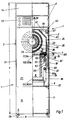
- the main components of the dental workbench T are a work station P, a latter assigned Suction device S and one under the worktop arranged filter device 1, which in to be described Forms a support column for the work table T and thereby due to its compact column shape a satisfactory large space F under the work table T guaranteed.
- the filter device 1 is first of all essential Details described.
- the filter device 1 is in one with its associated devices cuboid housing 2 integrated, the width of which is smaller is built as its depth and that is relatively narrow and tall and is therefore columnar. Seen in the front view, his is Width b about 30 cm, its backward depth t about 60cm and its height h about 80 cm. This size doesn't just allow that To set up filter device 1 in a space-saving manner, but it is also suitable in addition, dental workplaces, in particular tables, as an accessory to be assigned.
- the filter device 1 is adjustable in height, preferably by means of screws screwed vertically into the housing base and determined screws 2a.
- the operating side of the filter device 1 is facing the front of the work table. However, it is also possible to arrange the operating side on the side or the back or at least a switch for the filter device on or on the work table to arrange.
- the housing 2 delimits three main sections arranged one above the other, namely a lower main department 3, in which a suction device, here in the form of a fan 5 driven by a motor 4, unordered is, a central department 6, in which the actual Filter device 7 in the upper area of the main department 6 and below a filter material collecting container 8 are arranged, and an upper one Department 9 for other facilities involved in the present Organization in two superimposed individual departments is divided to accommodate an electronic control device 13 and a compartment 14 for tools or accessories, e.g. in form of a Drawer is formed, which in the present embodiment Compartment 14 is arranged above the compartment for the control device 13. At the Front side part of the control device 13 receiving Individual department are manual controls and Display elements arranged.
- the aforementioned main departments or main functional departments 3, 6 and 9 extend substantially from the front wall 15 to Rear wall 16 and from one to the other side wall 17, 18, the middle main department 6 essentially one on the front the associated main opening covering the entire front part 19, which through a door 21 by means of an opening edge seal sealable and therefore accessible from the front is.
- the lower one Department 3 should be accessible from the front.
- the lower main department 3 accessible through the central main department 6. This is the bottom wall 22 of the central main department 6 detachable and arranged removable upwards and forwards. After taking out the bottom wall 22 is thus the lower main department 3 accessible from above through the main opening 19.
- the upper main department is similar 9 accessible from the front, the electronic control device 13 in the form of several individual parts or as a block, here in the drawer, can be pulled out to the front and thus by are accessible at the front. There are none in the side walls 17, 18 Access openings available so that the filter device 1 laterally can be hired immediately.
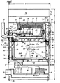
- the filter device 7 has - apart from necessary Entry and exit openings - closed filter device housing 23 on that by a horizontal division 24 divided into a lower part 26 and an upper part 25 is, the lower part 26 through the cup-shaped collecting container 8 is formed, the top of a rectangular container opening 27, which below the filter 28 of the filter device 7 is arranged.
- the filter device 7 has one Holding device 29 for the hollow cylindrical filter 28, which can be rotated about an axis of rotation 33 by means of an electric motor 32 which is horizontal in the present embodiment and at right angles to the operating side 34, i.e. from the front extends to the rear, making the relatively narrow Width B and the relatively large depth T of the filter device 1 be used well.
- an annular seal 24a Between the top 25 and the lower part 26 is an annular seal 24a, which preferably attached to one of these parts, in particular glued, is.
- the upper part 25 of the filter device housing 23 is with vertical side walls 35, a vertical front wall 36 and a substantially vertical rear wall 37 box-shaped shaped, with the upper portion of the filter device housing 23 is polygonal or rounded dome-shaped.
- a round support tube 38 fixed with radial holes 40 that the rear wall 38th Push through to the rear and with an extension on the back a connector 39 for a hose or a Pipe can have.
- the electric motor 32 is flanged coaxially, the drive shaft journal 41 extends coaxially forward.
- a drive flange 42 is seated in a rotationally fixed manner a hub on which the front of two round washers 44a, 44b can be screwed on.
- the rear holding disc 44b is by means of a Rolling bearing 45 on the rear area of the support tube 38 free rotatably mounted and sealed by means of an annular seal 46.
- the holding disks 44a, 44b point towards one another Pages one each on the cross-sectional shape and Size of the filter 28 adapted ring groove in which the hollow cylindrical filter 28 sits with its ring ends.
- the filter 28 Preferably is also here within the filter 28 hollow cylindrical safety filter 48 arranged and between the holding disks 44a, 44b held here each have another inner annular groove in which the Ring ends of the safety filter 48 sit. Between the filter 28 and the safety filter 48 is a radial distance and thus an annular space 51 is present. The filter 28 or the safety filter 48 thus surround the support tube 38 and the electric motor 32 coaxially and a radial distance, whereby a further ring free space 52 is formed.
- the support tube 38 and the electric motor rigidly connected thereto 32 are by a support bearing 53 on the front wall 36 of the Supported top 26.
- the upper part 25 has on the front side a mounting opening 54 which is larger than that front washer 44a and filter 28 so that these Parts can be assembled or disassembled from the front.
- the Mounting opening 54 which in the present embodiment occupies almost the entire area of the front wall 36 can be closed tightly by a lock door.
- a folding door that can be folded down 55 provided in the area of its lower edge in a Joint 56 is articulated with a horizontal joint axis and a bearing part fastened on the inside, here a bearing hub 58, carries, when closing the folding door 55 in or on a suitable bearing part, here a bearing journal 57, is pluggable by means of a roller bearing 61 in the hub of the Drive flange 42 rotatably supported and thereby held axially is so that when the flap door 55 is opened on the drive flange 42 remains.
- the aforementioned Bearing parts 57 and 58 automatically merged, wherein in between a preferably positive locking device may be present so that the bearing part 57 is not in operation turns with.
- the division joint 24 is in a downward direction Distance from the bottom of the filter 28.
- the filter device housing 23 is vibration-damped, namely floating vertically and horizontally or springy stored in the housing 2.
- a suspension device is used for this 62 with elastic support parts, especially rubber pieces, on upper area of the upper part 26.
- FIG. 1 clearly shows are on the upper part 26 laterally protruding angle support legs 64 attached, which attached to the housing 2 overlap horizontal support rails 65, the support legs 64 with the interposition of elastic rubber pieces on the Support rails 65 are supported.
- This configuration enables simple and easy assembly of the filter device housing 23 by pushing in or pulling out in front.
- Between vertical webs of the support legs 64 and Support rails 65 can preferably vibration dampers 67 in Form of rubber pieces may be present, with horizontal cross bolts vertical webs of the support legs 64 and support rails 65 and the vibration damper 67 can grasp.
- the pot-shaped collecting container 8 has one flat bottom wall 68 of rectangular shape and four of them upwardly extending peripheral walls, namely two each other opposite side walls 69 and a front wall 71 and a rear wall 72 so that the rectangular container opening 27 results, which is limited by the peripheral walls and their shape and size of the underside opening of the upper part 26 corresponds.
- the upper edge area of the collecting container 8 is by an outwardly projecting collar 70 with a laterally protruding collar legs and one from this collar legs extending upward, one upward Limit open outer channel 76. Both through the perimeter walls formed inner edge 77 and the outer edge 78 lie close to the flat ring seal 24a on one Edge flange is attached to the lower edge of the upper part 26.
- the height of the collecting container 8 is somewhat smaller than the vertical distance between supporting parts on the bottom wall 22, on which the collecting container 8 can be set up and the underside of the upper part 26.
- the collecting container 8 can thus conveniently inserted into the central main department 6 from the front and be pulled out.
- a closing device 81 which the collecting container 8th engages and presses upwards against the upper part 26 and in this position.
- locking devices arranged in mirror image 81 with pressure parts e.g.
- Pressure pin 82 provided on a bearing pin 80 pivotally mounted lever arm 83 are attached by under the collar 70 on the outside in an approximately middle position and by pivoting these pressure bolts 82 through simultaneous turning of the lever arms arranged on both sides 82 lift the collection container 8 and against the ring seal Press 24a.
- the pressure bolts 82 are located directly above the associated one Bearing pin 80 or preferably slightly behind the upper one Dead center, causing an automatic release of the locking device 81 is prevented.
- For simultaneous rotation of the Lever arms 83 serve a U-shaped hand bracket 85, which is the collection container 8 engages in a U shape from the front.
- the axes of rotation 80 can on the side walls 17, 18 of the housing 2 can be attached.
- the axes of rotation 80 are attached to the upper part 26 here on projecting down from the side walls of the upper part 26 Sidewalls 87 attached. This also makes the locking device 81 part of the filter assembly, and therefore it is not only vibration-damped with this unit, but it can also be pre-assembled on this unit become.
- the hand bracket 85 is preferably arranged and dimensioned such that that its free temple end in the closed position (in Fig. 2 shown with solid lines) immediately behind the inner surface of the door 21 and thereby in a larger one Vertical distance from the bearing pin 80 is located.
- the door 21 can only be closed when the hand strap 85 is in its closed position. If the closure is incorrect, the Hand strap 85 above its closed position, due to its arc movement in the range of movement of the door 21 stands in so that it cannot be closed. This creates a mechanical safety device which clearly indicates to the operator that the Collection container 8 is not tightly connected. This is particularly so when filtering harmful substances important as it is also used in dental technology, to prevent these substances from entering the outside Filter device 1 work area.
- the hand bracket 85 is included its free U ends attached to double arms 83a of the lever arms 83.
- Another U-shaped locking bracket 88 provided which extends downward from the lever arms 83 and engages under the collecting container 8 with its strap web 89 and at the same time additionally supports what the pressure load from the pressure bolts 82 on the collar 70 can be reduced.
- the preferably made of ferro-magnetic material such as steel Slider 103 can by means of a holding device or a guide slidably and tightly held on the upper housing part 25, e.g. by means of at least one, in particular arranged on the back, or several distributed permanent magnets 100, and against the Seal 24a can be pulled or pressed to seal during the To improve the absence of the collecting container 8.
- the guide rails 105 are preferably angular rails, which are laterally are attached to the upper housing part 25 (Fig. 1).
- the slider 103 is 8 before lowering the collecting container from a parking position 103b, in which it is under the collecting container 8 is inserted, removed, otherwise the works Lowering mechanism not because it is locked.
- the collecting container 8 can also not be emptied bring it into the functional position, if not before the slide 103 has been removed from a parking position 103b. This leaves can be achieved in that the hand strap 85, here the strap bar 89, against the preferably front end of the closure part 103 bumps in the trajectory of the closure member 103 protrudes in its parking or parking position, i.e. of the Stand lever 85 cannot be placed under the collecting container 8 pivot, so that the door 21 can not be closed.
- the lifting height of the connection or coupling device is somewhat dimensioned larger than the thickness of the closure part 103.
- the closed position of the closure part 103 is the front one End near or directly behind the door 21. This is preferably the case also for the parking position. If the door 21 is is not an indication that the proper or tight connection of the collection container is not is guaranteed. Through a switch contact (not shown) this can be done between the door 21 and the housing 2 by a buzzer acoustically or by a warning lamp visualize it, or it can also be Circuit prevent the filter device from being switched on. A such a switching contact can also between the housing 2 or Attachments and the closure part 103 in its closed position be effective.
- a bag in the collecting container 8 92 is also advantageous to have a bag in the collecting container 8 92 to be arranged in particular from plastic film, which is preferred is so deep that its free edges for the Disposal e.g. can be decided by knotting.
- the bag 92 is to be sealed at the edge of the collecting container 8, so there is no filter material behind the bag 92 or in reaches the interior of the housing 2.
- the protruding edge 93 of the in the collection container 8 inserted bag 92 over the inner edge 77 carded and optionally folded into the outer groove 76 inserted. As a result, the edge 93 is between the inner edge 77 and the ring seal 46 clamped.
- the filter device housing 23 is preferably attached to one flexible feed line 95, in particular hose line, for air to be filtered, which the rear wall 16 of the Device housing 2 in one implementation, e.g. in form of Connection piece 95a, interspersed and to a line connection is connected in the rear wall 37 of the upper part 26.
- Another preferably flexible pipe or hose section extends from the connecting piece 39 of the support tube 38 to the fan 5, being connected to a connecting piece 96 of the bottom wall 22 is connected, which is behind the Collection container 8 is located.
- the fan 5 Located under the bottom wall 22 the fan 5 in another line section 98 in the lower main department 3, which is U-shaped to one Activated carbon filter 99 and then extends to the rear wall 16, the it penetrates in an implementation 98a and to the one further Drain line can be connected.
- the function of the filter device 1 is described below.
- the collecting container 8 Before a filtering process, the collecting container 8 is close to To connect upper part 26.
- the fan 5 can then be switched on, whereby the filtering process begins.
- the Fan 5 sucks the air to be filtered due to the air flow Air into the interior of the filter device housing 23, which is enlarged due to its compared to the feed line 95 Volume represents a calming room 101.
- the last end region of the feed line 95 is slanted towards directed below, preferably in the middle of the collecting container 8.
- the rear wall 37 of the upper part 26 in the area of the feed line bushing to the rear sloping.
- Lighter filter material is turned upwards with the air flow Filter 28 directed, including the security filter 48 the air flow radially inwards over the entire lateral surface flows through and through the radial holes 40 in the Carrier tube 38 and then flows to the fan 5.
- Print side from the fan 5 the air is still through the activated carbon filter 99 out, and it can then in the the filter device 1 surrounding room or not in one pipe or hose line shown continued and on the outside atmosphere are released.
- When flowing through the Filters 28 store the filter material on its outer surface so that the permeability of the filter 28 is reduced and the negative pressure in the area between the fan 5 and the filter 28 increases.
- the fan 5 or electric motor 32 is preferably so speed-controlled that the amount of air delivered is always one predetermined, optimal value corresponds to what is in accordance e.g. a flow meter by means of a control device can be regulated. This not only makes one too big Air promotion or consumption prevented, but in the Case by removing the air to be filtered from a dental Vacuumed workplace is prevented on the one hand that there is an unpleasant draft on the user's hands, or on the other hand too little air is extracted.
- the bag 92 is that when the fan is switched on and off 5 and also due to different degrees of contamination of filter 28 exposed to pressure differences that correspond to Movements of the bag wall cause it to be significant is stressed and can tire and break. This The problem is particularly dangerous when filtering Substances of particular importance.
- To these strains Avoid bag 92 is at least one to the outside of the bag leading bypass is provided leading to a Pressure equalization inside and outside the bag 92, whereby the aforementioned loads on the bag 92 are avoided are.
- the cleaning effect can be accelerated by the fact that during the rotation, i.e. during the loading of the filter material with centrifugal force, the filter 28 is slightly shaken, e.g. by knocking or vibrating. Such shocks force the removal of the filter material from the filter 28.
- the filter 28 can automatically be rotated when a certain negative pressure is exceeded.
- a differential pressure measuring device can also be used or a differential pressure switch can be used, the Vacuum difference before and after the filter 28 measures.
- a pressure sensor 104a in the housing upper part 25 and a vacuum sensor 104b in the flow line between filters 28 and fan 5 may be provided.
- the vacuum sensor only a display that the operator operates signals that the filter 28 manually for a certain time long to be rotated. For this case a corresponding operating element is assigned to the filter device 1.
- Another possibility is - if none Vacuum sensor is provided - a rotation of the filter 28 in irregular or regular (e.g. every tomorrow).
- Air volume can be monitored or measured by one turn the filter 28 to determine and initiate.
- the filtering process can be started again after switching off the rotation be started.
- the collecting container 8 is a device for monitoring or measurement of the level assigned. It can be a sight glass or an electrically functioning device act.
- a filter device 1 according to the invention is suitable in each case for one or two dental workplaces, or with the appropriate capacity design, it can also be used with a Plenty of jobs to be connected.
- the fan 5 depending on the activation of a processing device in at least one of the existing workplaces to control so that at least only when switched on one of the existing tools the fan is put into operation.
- the filter device 1 is in the range a table leg Ta arranged, being it as a support column 110 forms a table leg Ta and thus a common table leg replaced.
- the depth t of the filter device 1 is preferably at adjusted the width B of the work table T or a little less dimensioned so that the work table T has a good stability owns.
- the filter device 1 in its front and rear area assigned height adjustable Foot pieces 2a a height adjustment and adjustment performed on unevenness of the floor in a simple manner become. Vertical screws are preferably provided, with their heads on the floor and through a nut in its screwed height adjustment are noticeable.
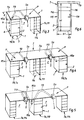
- the filter device 1 replaces a table leg Ta in the form of a lateral vertical side plank 111 as seen on the opposite side of the work table T, here on the right, is present and extends from the floor to the underside of the worktop Tb and preferably on the side outer edge the worktop Tb is arranged.
- the suction device S is one per se usual design with a suction hood Sa, which in the middle Front edge area of the worktop Tb is attached and with its suction opening towards the back of the work surface Worktop Tb is directed.
- the suction hood Sa is through one that extends to the rear just below the worktop Tb Suction pipe or hose 113 with the inlet connection 95a of the filter device 1 connected.
- Fig. 3 is hinted shown that the table leg or the side plank 111 through a support column 114 with several one above the other arranged drawers and compartments can be replaced or such a support column 114 on the inside of the side plank 111 arranged or attached to it as a floating box can be.
- a work table T with two arranged side by side Jobs P on both sides a filter device 1 as Support column 110 arranged, being in the middle between the workplaces P a table leg Ta in the form of a side plank 111, one or two support columns 114 or in another form can be.
- the filter device 1 differs from the previously described exemplary embodiments in that the filter device 1 not laterally but is arranged centrally under the worktop Tb, whereby to A work station P is provided on both sides of the filter device 1 can be. Only one or both of these jobs can be done P be equipped with a suction device S. If two suction devices S are provided, it is necessary a branch 95b for connecting the two suction hoses 113 with the filter device 1. There can be side planks on both sides 111 and / or support columns 114 may be provided.
- the housing forms 2 of the filter device 1, the support column 110. It is within the However, the invention also makes it possible to support the support column 110 additional box-shaped housing 115 of corresponding width b1, height h1 and depth with two side walls 116, if necessary a bottom wall 117 and possibly a rear wall to form a front insertion opening 119 in a has such size that the associated cross-sectional dimensions the filter device 1 is adapted so that the latter optionally from the front into the additional housing 115 can be pushed in and pulled out again.
- Such an arrangement allows either a filter device 1 or a box, not shown, of corresponding dimensions with drawers arranged one above the other - similar to the support column 114 - to be provided and by inserting or pulling out to mount optionally. This will make a desired one Variability and also retrofittability in a simple and advantageous way Wisely taken into account.
- a filter device 1 in the configurations 3 to 5 optionally to provide or subsequently exchange what through the use of detachable fasteners and e.g. Screws possible in a simple way is.
- the inlet port 95a or inlet not on the back but in the rear area of the Arrange inside of the filter device 1 or housing 115.
- the exhaust air from the filter device 1 can both directly into the room are blown (no energy losses) as well as over a Exhaust duct system that can be connected to it is directed outside become.
Landscapes
- Health & Medical Sciences (AREA)
- Chemical & Material Sciences (AREA)
- Chemical Kinetics & Catalysis (AREA)
- Oral & Maxillofacial Surgery (AREA)
- Dentistry (AREA)
- Epidemiology (AREA)
- Life Sciences & Earth Sciences (AREA)
- Animal Behavior & Ethology (AREA)
- General Health & Medical Sciences (AREA)
- Public Health (AREA)
- Veterinary Medicine (AREA)
- Filtering Of Dispersed Particles In Gases (AREA)
Description
- Fig. 1
- ein Filtergerät mit integrierter Saugeinrichtung als säulenförmige kompakte Baueinheit in der Vorderansicht, teilweise vertikal geschnitten;
- Fig. 2
- das Filtergerät im seitlichen Vertikalschnitt;
- Fig. 3
- einen erfindungsgemäßen zahntechnischen Arbeitstisch mit einem Arbeitsplatz, einer Absaugvorrichtung und dem Filtergerät nach den Fig. 1 und 2 in perspektivischer Vorderansicht;
- Fig. 4 und 5
- einen erfindungsgemäßen Arbeitstisch in abgewandelten Ausgestaltungen;
- Fig. 6
- eine Einzelheit des erfindungsgemäßen Arbeitstisches in weiterer abgewandelter Ausgestaltung.
Claims (5)
- Zahntechnischer Arbeitstisch (T),mit einer Tischplatte (Tb), die auf einem Traggestell (Ta) angeordnet ist,mit wenigstens einem, auf der Tischplatte (Tb) angeordneten Arbeitsplatz (P) mit einer Absaugvorrichtung (S), undmit einem Filtergerät (1),
dadurch gekennzeichnet,daß das Filtergerät (1) ein quaderförmiges Gehäuse (2) aufweist, dessen Breite (b) geringer ist als dessen Tiefe (t) und Höhe (h), und das eine Tragsäule (110) bildet, die in ihrem Bereich das Traggestell (Ta) ersetzt,daß in dem Gehäuse (2) eine Filtervorrichtung (7) und darunter ein Filtergut-Sammelbehälter (8) angeordnet sind, die von vorne zugänglich sind, und daß das Filtergerät (1) seitlich neben dem Arbeitsplatz (P) angeordnet ist und durch einen sich unter der Tischplatte (Tb) erstreckenden Saugleitungsabschnitt (113) mit der Absaugvorrichtung (S) verbunden ist. - Zahntechnischer Arbeitstisch nach Anspruch 1,
dadurch gekennzeichnet,
daß die Höhe (h, h1) der Tragsäule (110) dem Abstand der Tischplatte (Tb) vom Boden entspricht. - Zahntechnischer Arbeitstisch nach einem der vorhergehenden Ansprüche,
dadurch gekennzeichnet,
daß bei einem Arbeitstisch (T) mit zwei nebeneinander angeordneten Arbeitsplätzen (P) an beiden Seiten des Arbeitstisches (T) ein eine Tragsäule (110) bildendes Filtergerät (1) oder ein gemeinsames eine Tragsäule (110) bildendes Filtergerät (1) an einer Seite oder in mittlerer Position vorgesehen ist. - Zahntechnischer Arbeitstisch nach einem der vorhergehenden Ansprüche,
dadurch gekennzeichnet,
daß die Absaugvorrichtung (S) durch eine im mittleren Vorderkantenbereich des zugehörigen Arbeitsplatzes (P) angeordnete Absaughaube (Sa) gebildet ist, die durch den Saugleitungsabschnitt (113) mit dem zugehörigen Filtergerät (1) verbunden ist, oder mehrere Absaughauben (Sa) mittels zugehörigen Saugleitungsabschnitten (113) und einem Abzweig (95b) mit einem gemeinsamen Filtergerät (1) verbunden sind. - Zahntechnischer Arbeitstisch nach einem der vorhergehenden Ansprüchen,
dadurch gekennzeichnet,
daß eine Abluftleitung (98a) des Filtergeräts (1) in den das Filtergerät (1) umgebenden Raum oder außerhalb des das Filtergerät aufnehmenden Raumes (Gebäudes) mündet, z.B. im Freien.
Applications Claiming Priority (2)
| Application Number | Priority Date | Filing Date | Title |
|---|---|---|---|
| DE4235714A DE4235714A1 (de) | 1992-10-22 | 1992-10-22 | Zahntechnischer Arbeitsplatz mit einem Arbeitstisch und einer Absaugeinrichtung mit einem Filtergerät |
| DE4235714 | 1992-10-22 |
Publications (3)
| Publication Number | Publication Date |
|---|---|
| EP0598246A2 EP0598246A2 (de) | 1994-05-25 |
| EP0598246A3 EP0598246A3 (de) | 1995-05-24 |
| EP0598246B1 true EP0598246B1 (de) | 1999-01-07 |
Family
ID=6471118
Family Applications (1)
| Application Number | Title | Priority Date | Filing Date |
|---|---|---|---|
| EP93117196A Expired - Lifetime EP0598246B1 (de) | 1992-10-22 | 1993-10-22 | Zahntechnischer Arbeitsplatz mit einem Arbeitstisch und einer Absaugeinrichtung mit einem Filtergerät |
Country Status (2)
| Country | Link |
|---|---|
| EP (1) | EP0598246B1 (de) |
| DE (2) | DE4235714A1 (de) |
Cited By (1)
| Publication number | Priority date | Publication date | Assignee | Title |
|---|---|---|---|---|
| CN112641215A (zh) * | 2021-01-08 | 2021-04-13 | 李理白 | 一种可拆卸式安全供暖书桌 |
Families Citing this family (6)
| Publication number | Priority date | Publication date | Assignee | Title |
|---|---|---|---|---|
| DE4414936B4 (de) * | 1994-04-28 | 2009-08-06 | Kaltenbach & Voigt Gmbh & Co. Kg | Verfahren zur Steuerung der Absaugleistung einer zentralen Absaugvorrichtung und Vorrichtung zur Durchführung des Verfahrens |
| DE19544967A1 (de) * | 1995-12-04 | 1997-06-05 | Zubler Geraetebau | Staufachmodul |
| DE19801316A1 (de) * | 1998-01-15 | 1999-07-22 | Kaltenbach & Voigt | Medizinischer oder dentaltechnischer Arbeitstisch |
| CN116352896B (zh) * | 2023-04-06 | 2023-12-26 | 江苏捷达交通工程集团有限公司 | 便于拿取的小型切割机 |
| WO2024258504A2 (en) * | 2023-06-14 | 2024-12-19 | Apex Brands, Inc. | Air filtration system with main and subsidiary assemblies |
| CN116944187B (zh) * | 2023-09-19 | 2023-12-05 | 山西北都科技股份有限公司 | 一种焙烧用吸卸料天车除尘装置 |
Family Cites Families (6)
| Publication number | Priority date | Publication date | Assignee | Title |
|---|---|---|---|---|
| DE7603786U1 (de) * | 1976-02-10 | 1976-10-28 | Kaltenbach & Voigt, 7950 Biberach | Arbeitstisch zur Pflege von ärztlichen, insbesondere zahnärztlichen Instrumenten |
| US4108509A (en) * | 1977-03-18 | 1978-08-22 | Futurecraft Corporation | Controlled environment work enclosure |
| CH641663A5 (en) * | 1978-06-05 | 1984-03-15 | Kaltenbach & Voigt | Device for processing workpieces, especially dental laboratory products |
| DE2913871C2 (de) * | 1979-04-06 | 1984-03-22 | Otto Schmidt Dental-Laboratorium, 7000 Stuttgart | Staubabsaugvorrichtung in einem Arbeitstisch der Feinwerktechnik |
| FR2576539B1 (fr) * | 1985-01-30 | 1987-03-20 | Meriau Mecanique Electronique | Etabli de prothesiste a circuits selectifs de retenue des debris |
| DE8608496U1 (de) * | 1986-03-27 | 1986-05-15 | Maschinenbau Harnisch & Rieth Gmbh & Co, 7065 Winterbach | Absauggerät |
-
1992
- 1992-10-22 DE DE4235714A patent/DE4235714A1/de not_active Ceased
-
1993
- 1993-10-22 EP EP93117196A patent/EP0598246B1/de not_active Expired - Lifetime
- 1993-10-22 DE DE59309276T patent/DE59309276D1/de not_active Expired - Lifetime
Cited By (1)
| Publication number | Priority date | Publication date | Assignee | Title |
|---|---|---|---|---|
| CN112641215A (zh) * | 2021-01-08 | 2021-04-13 | 李理白 | 一种可拆卸式安全供暖书桌 |
Also Published As
| Publication number | Publication date |
|---|---|
| DE59309276D1 (de) | 1999-02-18 |
| DE4235714A1 (de) | 1994-05-05 |
| EP0598246A3 (de) | 1995-05-24 |
| EP0598246A2 (de) | 1994-05-25 |
Similar Documents
| Publication | Publication Date | Title |
|---|---|---|
| DE702145C (de) | Beutelloser Staubsauger | |
| EP0740922A1 (de) | Nassreinigungsgerät | |
| DE973926C (de) | Staubsauger, insbesondere fuer Haushaltungen, mit einer Reinigungsvorrichtung fuer das Staubfilter | |
| DE2243075B1 (de) | Maschine zum reinigen oder konservieren oder zur schaedlingsbekaempfung | |
| DE2343971C3 (de) | Gerät zur Fußbodenpflege | |
| EP0598246B1 (de) | Zahntechnischer Arbeitsplatz mit einem Arbeitstisch und einer Absaugeinrichtung mit einem Filtergerät | |
| EP0594216B1 (de) | Filtergerät für ein gasförmiges Medium | |
| DE2856115A1 (de) | Staubsauger, vorzugsweise fuer die gewerbliche verwendung | |
| EP0930134B1 (de) | Medizintechnischer oder dentaltechnischer Arbeitstisch | |
| EP0594213B2 (de) | Filtergerät für ein gasförmiges Medium | |
| DE1628859A1 (de) | Fussbodenpflegemaschine | |
| DE4203958C1 (de) | ||
| DE2913871A1 (de) | Staubabsaugvorrichtung in einem arbeitstisch der feinwerktechnik fuer sitzende taetigkeit | |
| EP4011481B1 (de) | Entstaubungsvorrichtung mit einer steuerung für wenigstens zwei betriebsmodi und verfahren zur steuerung einer entstaubungsvorrichtung | |
| DE4414936B4 (de) | Verfahren zur Steuerung der Absaugleistung einer zentralen Absaugvorrichtung und Vorrichtung zur Durchführung des Verfahrens | |
| DE19515997C1 (de) | Filtergerät für ein gasförmiges Medium, insbesondere Luft, das feste auszufilternde Partikel enthält | |
| EP0067422B1 (de) | Mobiles Absauggerät für Stäube, Farbnebel, Dämpfe und dergleichen | |
| DE19509432C2 (de) | Absaugvorrichtung, insbesondere für Zahntechniker-Arbeitsplätze | |
| DE3723148A1 (de) | Schmutzsaugerentsorgung | |
| DE4413243A1 (de) | Staub- und Wassersauger | |
| DE19514068A1 (de) | Verfahren und Vorrichtung zum Reinigen eines Filters für ein gasförmiges Medium, das feste, auszufilternde Partikel enthält | |
| EP0509052B1 (de) | Vorrichtung zum reinigen mechanischer geräte, kleinteile und/oder elektronischer schalteinheiten | |
| DE9400035U1 (de) | Gebläse für ein Kehr- oder Saugfahrzeug | |
| DE9400842U1 (de) | Vorrichtung zur Staubabsaugung an Steintrennmaschinen | |
| DE1008955B (de) | Vorrichtung zum Auflockern von Heu, Stroh od. dgl. fuer landwirtschaftliche Zwecke |
Legal Events
| Date | Code | Title | Description |
|---|---|---|---|
| PUAI | Public reference made under article 153(3) epc to a published international application that has entered the european phase |
Free format text: ORIGINAL CODE: 0009012 |
|
| AK | Designated contracting states |
Kind code of ref document: A2 Designated state(s): DE FR IT |
|
| PUAL | Search report despatched |
Free format text: ORIGINAL CODE: 0009013 |
|
| AK | Designated contracting states |
Kind code of ref document: A3 Designated state(s): DE FR IT |
|
| 17P | Request for examination filed |
Effective date: 19950627 |
|
| 17Q | First examination report despatched |
Effective date: 19970506 |
|
| GRAG | Despatch of communication of intention to grant |
Free format text: ORIGINAL CODE: EPIDOS AGRA |
|
| GRAG | Despatch of communication of intention to grant |
Free format text: ORIGINAL CODE: EPIDOS AGRA |
|
| GRAH | Despatch of communication of intention to grant a patent |
Free format text: ORIGINAL CODE: EPIDOS IGRA |
|
| GRAH | Despatch of communication of intention to grant a patent |
Free format text: ORIGINAL CODE: EPIDOS IGRA |
|
| GRAA | (expected) grant |
Free format text: ORIGINAL CODE: 0009210 |
|
| AK | Designated contracting states |
Kind code of ref document: B1 Designated state(s): DE FR IT |
|
| ET | Fr: translation filed | ||
| REF | Corresponds to: |
Ref document number: 59309276 Country of ref document: DE Date of ref document: 19990218 |
|
| ITF | It: translation for a ep patent filed | ||
| PLBE | No opposition filed within time limit |
Free format text: ORIGINAL CODE: 0009261 |
|
| STAA | Information on the status of an ep patent application or granted ep patent |
Free format text: STATUS: NO OPPOSITION FILED WITHIN TIME LIMIT |
|
| 26N | No opposition filed | ||
| PGFP | Annual fee paid to national office [announced via postgrant information from national office to epo] |
Ref country code: FR Payment date: 20051019 Year of fee payment: 13 |
|
| PG25 | Lapsed in a contracting state [announced via postgrant information from national office to epo] |
Ref country code: IT Free format text: LAPSE BECAUSE OF NON-PAYMENT OF DUE FEES Effective date: 20051022 |
|
| REG | Reference to a national code |
Ref country code: FR Ref legal event code: ST Effective date: 20070629 |
|
| PG25 | Lapsed in a contracting state [announced via postgrant information from national office to epo] |
Ref country code: FR Free format text: LAPSE BECAUSE OF NON-PAYMENT OF DUE FEES Effective date: 20061031 |
|
| PGFP | Annual fee paid to national office [announced via postgrant information from national office to epo] |
Ref country code: DE Payment date: 20091029 Year of fee payment: 17 |
|
| REG | Reference to a national code |
Ref country code: DE Ref legal event code: R119 Ref document number: 59309276 Country of ref document: DE Effective date: 20110502 |
|
| PG25 | Lapsed in a contracting state [announced via postgrant information from national office to epo] |
Ref country code: DE Free format text: LAPSE BECAUSE OF NON-PAYMENT OF DUE FEES Effective date: 20110502 |