EP0596356B1 - Schaltvorrichtung - Google Patents
Schaltvorrichtung Download PDFInfo
- Publication number
- EP0596356B1 EP0596356B1 EP93117232A EP93117232A EP0596356B1 EP 0596356 B1 EP0596356 B1 EP 0596356B1 EP 93117232 A EP93117232 A EP 93117232A EP 93117232 A EP93117232 A EP 93117232A EP 0596356 B1 EP0596356 B1 EP 0596356B1
- Authority
- EP
- European Patent Office
- Prior art keywords
- contact
- conductor
- holding device
- switching device
- lead
- Prior art date
- Legal status (The legal status is an assumption and is not a legal conclusion. Google has not performed a legal analysis and makes no representation as to the accuracy of the status listed.)
- Expired - Lifetime
Links
Images

Classifications
-
- H—ELECTRICITY
- H01—ELECTRIC ELEMENTS
- H01F—MAGNETS; INDUCTANCES; TRANSFORMERS; SELECTION OF MATERIALS FOR THEIR MAGNETIC PROPERTIES
- H01F5/00—Coils
- H01F5/04—Arrangements of electric connections to coils, e.g. leads
Definitions
- the invention relates to a switching device, in particular for actuating valves, according to the features of the preamble of claim 1.
- switching devices which are also referred to as switching magnets, are known in various embodiments and are freely available on the market.
- the switching part is essentially formed from a tubular bolt which, when electrically excited Coil travels a predeterminable distance via the connected device plug and thereby triggers a switching operation, for example in the case of a valve for shutting off and guiding fluid flows.
- the holding device has two contact tabs made of easily weldable and electrically conductive material. At the two opposite ends of the contact lugs there are peg-like projections, which are wrapped by the respective end of the conductor for connecting the latter to the holding device.
- the two contact tabs on their sides facing away from the contact parts of the device plug each have a tab that can be attached to them, into which the conductor is inserted and then fixed by welding the two tabs to the contact tabs assigned to them.
- the contact parts with the contact lugs are also electrically conductively connected to one another by means of a welding process, so that an electrically conductive connection between the conductor of the coil former and the contact parts of the connector is subsequently made is made via the two contact flags.
- the thin coating of the conductor in the form of the insulation is removed and an electrically conductive connection is made at this point.
- This known switching device is complicated and expensive to manufacture due to the variety of parts. Furthermore, the known switching device is large because the contact lugs have a corresponding protrusion from the actual coil body.
- an ignition coil with a coil body which has a conductor winding.
- this has roof-like connecting pieces for the beginning and the end of the conductor winding.
- the mentioned connectors consist of bent contact springs, which have a clamping piece for clamping the two free ends of the conductor winding and pull the connecting device in such a way that they end in connector lugs. This enables an electrical connection to be made with a mating connector. Since the respective conductor ends are not guided by a holding device, but rather are inserted as freely movable conductor pieces in the associated roof-like connecting pieces, the assembly effort and the reject rate when assembling the known ignition coil are increased.
- a generic switching device which has a holding device made of plastic.
- the conductor ends of the winding are held in place after their insertion by splayed-off connecting pieces of two plug parts, which in turn are guided within two slots in the holding device.
- the plug parts connected to the coil body in this respect can then be introduced into a housing part, whereby the complete switching device is created and wherein a nose of the holding device is latched into a recess of the assigned housing part.
- the ends of the plug parts inserted through recesses in the housing part then form a connection option for a correspondingly designed mating plug.
- the conductor is guided through the holding device made of insulating material over a predetermined distance, but not in the area of the conductor ends themselves, which are to be inserted into the spread-apart connecting pieces of the plug parts during manufacture, which increases the assembly effort and the possible reject rate .
- the invention has for its object to provide the smallest possible switching device with a small number of parts that can be manufactured inexpensively, with a minimum rejection rate. This object is achieved by a switching device with the features of claim 1.
- the holding device associated with each contact part has two webs, each having a receptacle in which the conductor is guided, and in that the respective contact part has a roof-like connecting piece, which the conductor between the webs encompasses at least partially, a direct connection between the conductor and the two contact parts of the connector is possible without additional projecting tabs, which leads to a small-sized switching device.
- the roof-like connecting piece of the respective contact part which can be placed on the precisely positioned conductor piece running between the two pairs of webs of the holding device in the area of the respective conductor end, simplifies production and the switching device according to the invention can be produced more cheaply than the known solutions with a low reject rate.
- a welding process can be carried out between the conductor and the contact parts, in which the insulating material of the conductor is melted off.
- the solution according to the invention is small, so that smaller switching magnets can be built with the same properties, which is particularly the case with Use with valves plays a role where there are often tight installation conditions.
- An advantageous embodiment of the switching device according to the invention has a coil former 10 made of plastic material.
- the coil former 10 is provided with a winding 12 of a conductor 14, which is shown only schematically in FIG.
- a switching part (not shown) is guided in the form of a so-called pole tube in the coil former 10. When the switching device is actuated, the switching part can be used to control valves and thus determine their switching position.
- the bobbin 10 is almost flush with an essentially cylindrical housing part 16 made of metallic material.
- a holding device 18 is also formed from plastic material on one side of the coil former 10.
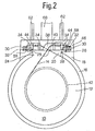
- the holding device 18 passes through an end recess 20 in the housing part 16 and is laterally in contact with the latter via a central piece 24, as is shown in particular in FIG.
- a flat plate 26 is arranged upwards on the middle piece 24 and forms a T-shaped base body of the holding device 18 with the middle piece 24.
- the lateral protrusions 28 lie in the transition area with the center piece 24 on the outer circumference of the housing part 16 and thus form a twist protection for the coil former 10 relative to the housing part 16.
- the holding device 18 has two peg-like extensions 30 arranged on the end of the base plate 26, around which the ends 32 of the conductor 14 are wound in order to ensure a firm connection of the conductor 12 to the holding device 18.
- two pairs of webs 34 are provided on the top of the plate 26 in the outer area, each of which has a receptacle 36 with a V-shaped cross section (see FIG. 1), in which the conductor 14 can be inserted.
- a guide bevel 38 is provided in the middle between the two webs 34 of the holding device 18 arranged directly opposite one another, by means of which the Conductor 14 crossing in the addressed area and without being touched at this point is guided (see Fig. 2,3).
- the turn package 12 is created and the conductor 14 is led out of the coil body 10 in such a way that it crosses the inlet slot 40 and the guide slope 38 into the receptacles 36 of the pair of webs 34 shown on the left in FIG reached. Then it is wrapped around the still free pin 30 and any excess ends of the conductor 14 are cut off.
- the conductor 14 is now guided by means of the holding device 18 over a predeterminable distance between the respective pairs of webs 34 in such a way that it is freely accessible from all sides for direct contact with two contact parts 44 of a device plug 46, since it is accessible from the webs 34 kept clear and taut and is at a distance from all fixed parts of the switching device between the respective receptacles 36 of a pair of webs 34.
- the device plug 46 has on its lower end facing the housing part 16 a peg-like projection 48 which engages in a bore 50 of the housing part 16 for establishing a connection.
- a latching part 52 can be provided on the housing part 16 for fixing the device plug 46, which engages under the holding device 18 along the recess 20, which at this point (see FIG. 1) has an axial projection 54 provided for this purpose having.
- the housing of the connector 46 and the locking part 52 are preferably formed from a plastic material and in view of this, a snap connection between the locking part 52 and the holding device 18 is possible.
- the respective contact part 44 of the device plug 16 has a roof-like connecting piece 56, which can be placed on the conductor piece between the two web pairs 34 from above.
- the two free leg pieces 58 of each connecting piece 56 which comprise the conductor 14 within the holding device 18, can be pressed together via the device and then welded to one another, the thin-walled plastic insulation of the conductor 14 being melted off, so that a conductive connection between the respective contact part 44 and the associated conductor piece of the conductor 14 is present.
- the roof-like connecting pieces 56 are connected to the outside with a flat contact track 60, on which is arranged perpendicular to it and connected to it there is a connector lug 62 which extends over the top of the switching device, as shown in particular in FIGS.
- a further contact track 64 is provided which forms the ground connection and which projects upwards with its one free end 66 as well as the connector tabs 62 and is welded to the outer periphery of the housing part 16 with its other free end 68 (see .Fig.1).
- All contact tracks 60 and 64 can be cut out or punched out of a flat board body and are then cast around with the plastic material of the connector 46.
- a socket 70 with an internal thread can be inserted in the connector 46 at the location of the pin-like projection 48, which ensures that the entire device is later attached to fixed parts and / or that the connector lugs 62 and 66 can be securely connected.
- the guide bevel 38 can also have a guide channel 72, the conductor 14 being placed in the interior of the channel, so that at the crossing point 74, at which the other end of the conductor is laid over the conductor 14 guided in the channel , there can be no short circuit. It is also sufficient, however, to let the conductor 14 run on one of the front sides of a guide or support of any kind, in which it is ensured that the crossing conductor pieces cannot touch each other due to their axial projection over the plate 26.
- the holding device 18, whose pairs of webs 34 form guide forks for the conductor 14, can be designed with a small overall height, so that, provided that the contact parts 44 cover the conductor 14 from above or from the side of the connector 46 on one side thereof create smaller dimensions for the switching device can be reached than was the case with the previously known.
Description
- Die Erfindung betrifft eine Schaltvorrichtung, insbesondere zum Betätigen von Ventilen, gemäß den Merkmalen des Oberbegriffen des Anspruches 1.
- Dahingehende Schaltvorrichtungen, die man auch als Schaltmagnete bezeichnet, sind in verschiedensten Ausführungsformen bekannt und auf dem Markt frei erhältlich. Das Schaltteil ist im wesentlichen aus einem rohrförmigen Bolzen gebildet, der bei elektrischer Erregung der Spule über den angeschlossenen Gerätestecker eine vorgebbare Wegstrecke zurücklegt und hierbei einen Schaltvorgang auslöst, beispielsweise bei einem Ventil zum Absperren und Führen von Fluidströmen. Die Haltevorrichtung weist zwei Kontaktfahnen aus gut schweißbarem und elektrisch leitfähigem Material auf. An den beiden einander abgewandten Enden der Kontaktfahnen sind zapfenartige Vorsprünge vorhanden, die von dem jeweiligen Ende des Leiters zum Verbinden desselben mit der Haltevorrichtung umwickelt sind. Ferner weisen die beiden Kontaktfahnen auf ihren den Kontaktteilen des Gerätesteckers abgewandten Seiten jeweils eine an sie anlegbare Lasche auf, in die der Leiter hineingelegt und anschließend fixiert wird, indem die beiden Laschen mit den ihnen zugeordneten Kontaktfahnen verschweißt werden. Nachdem die beiden winkelförmigen Kontaktteile des Gerätesteckers in Anlage gebracht sind mit den beiden Kontaktfahnen der Haltevorrichtung, werden die Kontaktteile mit den Kontaktfahnen ebenfalls über einen Schweißvorgang elektrisch leitend miteinander verbunden, so daß anschließend eine elektrisch leitende Verbindung zwischen dem Leiter des Spulenkörpers und den Kontaktteilen des Gerätesteckers über die beiden Kontaktfahnen hergestellt ist. Beim Schweißvorgang der angesprochenen Laschen wird der dünne Überzug des Leiters in Form der Isolierung beseitigt und eine elektrisch leitende Verbindung an dieser Stelle hergestellt.
- Diese bekannte Schaltvorrichtung ist aufgrund der Teilevielfalt kompliziert und teuer in der Herstellung. Ferner baut die bekannte Schaltvorrichtung groß auf, weil die Kontaktfahnen einen entsprechenden Überstand gegenüber dem eigentlichen Spulenkörper aufweisen.
- Durch die Vorrichtung nach der DE-PS 1 564 607 ist es bekannt, die elektrisch leitende Haltevorrichtung mit ihren beiden Kontaktfahnen zwischen den beiden Stegen eines endseitig an der Vorrichtung angeordneten Kunststoff-Stirnflansches festzulegen. Die zunächst stirnseitig an der bekannten Schaltvorrichtung vorstehenden beiden Kontaktfahnen werden mit dem jeweiligen Spulenende umwickelt und anschließend mit diesem verlötet. Um die Kontaktfahnen platzsparend unter einem Gehäusedeckel der Schaltvorrichtung unterbringen zu können und um die Spulenwicklungsenden vollständig von Zugspannungen zu entlasten, werden die Kontaktfahnen in Richtung auf die Haltevorrichtung zu umgebogen. Dieses nachträgliche Umbiegen des Lötanschlusses bedeutet im Hinblick auf die großen Stückzahlen, in denen solche Schaltvorrichtungen gefertigt werden, einen erheblichen Aufwand. Außerdem kann beim Umbiegen die Kontaktfahne abbrechen, was die Ausschußrate bei dieser bekannten Vorrichtung erhöht.
- Durch die WO-A-91/04411 ist eine Zündspule mit einem Spulenkörper bekannt, der eine Leiterwicklung aufweist. Zum Ankoppeln des Spulenkörpers an eine elektrische Anschlußeinrichtung weist diese dachartige Verbindungsstücke für den Anfang und das Ende der Leiterwicklung auf. Die angesprochenen Verbindungsstücke bestehen dabei aus umgebogenen Kontaktfedern, die ein Klemmstück zum Festklemmen für die beiden freien Enden der Leiterwicklung aufweisen und die Anschlußeinrichtung derart durchziehen, daß sie in Steckerfahnen enden. Hierdurch läßt sich ein elektrischer Anschluß mit einem Gegenstecker herstellen. Da die jeweiligen Leiterenden durch eine Haltevorrichtung nicht geführt sind, sondern als frei bewegbare Leiterstücke in die zugeordneten dachartigen Verbindungsstücke eingelegt werden, sind der Montageaufwand und die Ausschußrate beim Zusammenbau der bekannten Zündspule erhöht.
- Durch die US-A-5 153 550 ist eine gattungsgemäße Schaltvorrichtung bekannt, die eine aus Kunststoff bestehende Haltevorrichtung aufweist. Die Leiterenden der Wicklung werden nach ihrem Einlegen von abgespreizten Verbindungsstücken zweier Steckerteile festgehalten, die wiederum innerhalb zweier Schlitze in der Haltevorrichtung geführt sind. Die dahingehend mit dem Spulenkörper verbundenen Steckerteile lassen sich dann in ein Gehäuseteil einbringen, wodurch die vollständige Schaltvorrichtung entsteht und wobei eine Nase der Haltevorrichtung in eine Ausnehmung des zugeordneten Gehäuseteiles verrastet ist. Die durch Ausnehmungen in dem Gehäuseteil durchgesteckten Enden der Steckerteile bilden dann dort eine Anschlußmöglichkeit für einen entsprechend ausgestalteten Gegenstecker. Zwischen den Leiterenden und der Wicklung ist der Leiter durch die aus Isoliermaterial bestehende Haltevorrichtung über eine vorgegebene Wegstrecke geführt, jedoch nicht im Bereich der Leiterenden selbst, die in die abgespreizten Verbindungsstücke der Steckerteile bei der Herstellung einzulegen sind, was den Montageaufwand und die mögliche Ausschußrate erhöht.
- Ausgehend von diesem Stand der Technik liegt der Erfindung die Aufgabe zugrunde, eine möglichst klein aufbauende Schaltvorrichtung zu schaffen mit geringer Teileanzahl, die sich günstig herstellen läßt, mit minimaler Ausschußrate. Diese Aufgabe löst eine Schaltvorrichtung mit den Merkmalen des Anspruches 1.
- Dadurch, daß gemäß dem kennzeichnenden Teil des Anspruches 1 die Haltevorrichtung jedem Kontaktteil zugeordnet zwei Stege aufweist, die jeweils über eine Aufnahme verfügen, in der der Leiter geführt ist, und daß das jeweilige Kontaktteil ein dachartiges Verbindungsstück aufweist, das den zwischen den Stegen geführten Leiter zumindest teilweise umgreift, ist eine direkte Verbindung zwischen dem Leiter und den beiden Kontaktteilen des Gerätesteckers ohne zusätzliche vorstehende Kontaktfahnen möglich, was zu einer klein aufbauenden Schaltvorrichtung führt. Das dachartige Verbindungsstück des jeweiligen Kontaktteiles, das auf das jeweils zwischen den beiden Stegpaaren der Haltevorrichtung verlaufende, genau positionierte Leiterstück im Bereich des jeweiligen Leiterendes aufsetzbar ist, vereinfacht die Herstellung und die erfindungsgemäße Schaltvorrichtung ist mit geringer Ausschußrate kostengünstiger herstellbar als die bekannten Lösungen.
- Zum Herstellen einer einwandfreien elektrischen Verbindung kann zwischen dem Leiter und den Kontaktteilen ein Schweißvorgang durchgeführt werden, bei dem das Isoliermaterial des Leiters, abgeschmolzen wird. Die erfindungsgemäße Lösung baut klein auf, so daß sich bei gleichen Eigenschaften kleinere Schaltmagnete bauen lassen, was insbesondere beim Einsatz bei Ventilen eine Rolle spielt, wo häufig eng bemessene Einbauverhältnisse gegeben sind.
- Vorteilhafte Ausgestaltungen der erfindungsgemäßen Schaltvorrichtung sind Gegenstand der Unteransprüche.
- Eine vorteilhafte Ausgestaltung der erfindungsgemäßen Schaltvorrichtung wird nun im folgenden anhand der Zeichnung näher erläutert.
- Es zeigen:
- Fig.1
- einen Längsschnitt durch die obere Hälfte der Schaltvorrichtung;
- Fig.2
- eine Stirnansicht der Schaltvorrichtung gemäß Fig.1;
- Fig.3
- eine Draufsicht auf Teile der Haltevorrichtung und des Gerätesteckers.
- Eine vorteilhafte Ausgestaltung der erfindungsgemäßen Schaltvorrichtung weist einen Spulenkörper 10 auf aus Kunststoffmaterial. Der Spulenkörper 10 ist mit einer Wicklung 12 eines Leiters 14 versehen, die in der Fig.1 nur schematisch wiedergegeben ist. In dem Spulenkörper 10 ist ein Schaltteil (nicht dargestellt) geführt in Form eines sog. Polrohres. Mit dem Schaltteil lassen sich bei Betätigung der Schaltvorrichtung Ventile ansteuern und damit deren Schaltstellung bestimmen.
- Der Spulenkörper 10 schließt nahezu bündig mit einem im wesentlichen zylindrisch ausgebildeten Gehäuseteil 16 aus metallischem Werkstoff ab. Stirnseitig ist auf einer Seite des Spulenkörpers 10 eine Haltevorrichtung 18 ebenfalls aus Kunststoffmaterial angeformt. Die Haltevorrichtung 18 durchgreift eine stirnseitige Ausnehmung 20 im Gehäuseteil 16 und ist mit diesem über ein Mittelstück 24 seitlich in Anlage, wie dies insbesondere die Fig.2 zeigt. Wie die Fig.2 ferner zeigt, ist nach oben hin auf dem Mittelstück 24 eine eben verlaufende Platte 26 angeordnet, die mit dem Mittelstück 24 einen T-förmigen Grundkörper der Haltevorrichtung 18 ausbildet. Die seitlichen Überstände 28 liegen im Übergangsbereich mit dem Mittelstück 24 auf dem Außenumfang des Gehäuseteiles 16 auf und bilden somit einen Verdrehschutz für den Spulenkörper 10 gegenüber dem Gehäuseteil 16 aus.
- Die Haltevorrichtung 18 weist endseitig an der Grundplatte 26 angeordnet zwei zapfenartige Verlängerungen 30 auf, um die herum die Enden 32 des Leiters 14 gewickelt sind, um eine feste Verbindung des Leiters 12 mit der Haltevorrichtung 18 zu gewährleisten. Zur Gewährleistung einer weiteren Führung des Leiters mittels der Haltevorrichtung 18 sind auf der Oberseite der Platte 26 im jeweils äußeren Bereich zwei Paare an Stegen 34 vorgesehen, die jeweils über eine Aufnahme 36 verfügen mit einem V-förmigen Querschnitt (s.Fig.1), in die der Leiter 14 einlegbar ist. Mittig zwischen den zwei unmittelbar benachbart gegenüberliegend angeordneten Stegen 34 der Haltevorrichtung 18 ist eine Führungsschräge 38 vorgesehen, mittels der der Leiter 14 im angesprochenen Bereich sich kreuzend, und ohne sich an dieser Stelle zu berühren, geführt ist (s.Fig.2,3).
- Zum Herstellen der Wicklung mittels einer entsprechenden Vorrichtung (nicht dargestellt) wird zunächst das in Blickrichtung auf Fig.2 gesehen rechte Ende 32 des Leiters 14 auf die zugeordnete Verlängerung 30 gewickelt und anschließend der Leiter 14 in die Aufnahmen 36, gebildet aus dem rechten Paar an Stegen 34, eingelegt. Dann läuft der Leiter 14 dem Betrachter der Fig.2 zugewandt vor der Führungsschräge 38 und über einen Einlaufschlitz 40 (Fig.3), der auf der Rückseite der vorderen Stirnwand des Spulenkörpers 10 angeordnet ist, auf den Boden 42 des Spulenkörpers 10. Nach der vorgegebenen Windungszahl, z.B. 1700 Windungen, ist das Windungspaket 12 erstellt und der Leiter 14 wird aus dem Spulenkörper 10 derart herausgeführt, daß er den Einlaufschlitz 40 und die Führungsschräge 38 überkreuzend in die Aufnahmen 36 des in der Fig.2 links dargestellten Paares an Stegen 34 gelangt. Anschließend wird er um den noch freien Zapfen 30 gewickelt und die etwaig vorhandenen endseitigen Überstände des Leiters 14 werden abgeschnitten. Der Leiter 14 ist nun mittels der Haltevorrichtung 18 über eine vorgebbare Wegstrecke zwischen den jeweiligen Paaren an Stegen 34 derart geführt, daß er für eine unmittelbare Anlage mit zwei Kontaktteilen 44 eines Gerätesteckers 46 von allen Seiten aus frei zugänglich ist, denn er ist von den Stegen 34 frei- und straffgehalten und weist zu allen feststehenden Teilen der Schaltvorrichtung zwischen den jeweiligen Aufnahmen 36 eines Paares an Stegen 34 einen Abstand auf.
Der Gerätestecker 46 weist auf seinem dem Gehäuseteil 16 zugekehrten unteren Ende einen zapfenartigen Vorsprung 48 auf, der in eine Bohrung 50 des Gehäuseteiles 16 zum Herstellen einer Verbindung eingreift. Zusätzlich oder alternativ hierzu kann zum Festlegen des Gerätesteckers 46 auf dem Gehäuseteil 16 ein Rastteil 52 vorgesehen sein, das die Haltevorrichtung 18 längs der Ausnehmung 20 untergreift, die an dieser Stelle (s.Fig.1) einen hierfür vorgesehenen axialen Überstand 54 aufweist. Das Gehäuse des Gerätesteckers 46 sowie das Rastteil 52 sind vorzugsweise aus einem Kunststoffmaterial gebildet und im Hinblick hierauf ist eine Schnappverbindung zwischen dem Rastteil 52 und der Haltevorrichtung 18 möglich. - Das jeweilige Kontaktteil 44 des Gerätesteckers 16 weist ein dachartiges Verbindungsstück 56 auf, das von oben her auf das Leiterstück zwischen den beiden Stegpaaren 34 aufsetzbar ist. Die beiden freien Schenkelstücke 58 eines jeden Verbindungsstückes 56, die den Leiter 14 innerhalb der Haltevorrichtung 18 umfassen, lassen sich über die Vorrichtung zusammendrücken und anschließend miteinander verschweißen, wobei die dünnwandige Kunststoffisolierung des Leiters 14 abgeschmolzen wird, so daß eine leitende Verbindung zwischen dem jeweiligen Kontaktteil 44 und dem zugeordneten Leiterstück des Leiters 14 vorhanden ist. Die dachartigen Verbindungsstücke 56 sind jeweils nach außen hin versetzt mit einer ebenen Kontaktbahn 60 verbunden, auf der senkrecht zu ihr angeordnet und mit ihr verbunden eine Steckerfahne 62 vorhanden ist, die über die Oberseite der Schaltvorrichtung, wie dies insbesondere die Fig.1 und 2 zeigen, hinaussteht. Neben den bereits angesprochenen Kontaktbahnen 60 ist eine weitere Kontaktbahn 64 vorgesehen, die den Masseanschluß ausbildet und die mit ihrem einen freien Ende 66 ebenso wie die Steckerfahnen 62 nach oben absteht und mit ihrem anderen freien Ende 68 mit dem Außenumfang des Gehäuseteiles 16 verschweißt wird (s.Fig.1).
- Alle Kontaktbahnen 60 und 64 lassen sich aus einem ebenen Platinenkörper ausschneiden oder ausstanzen und werden anschließend mit dem Kunststoffmaterial des Gerätesteckers 46 umgossen. In dem Gerätestecker 46 kann an der Stelle des zapfenartigen Vorsprunges 48 eine Buchse 70 mit Innengewinde eingelassen sein, die ein späteres Befestigen der gesamten Vorrichtung an feststehenden Teilen und/oder eine sichere Anschlußmöglichkeit der Steckerfahnen 62 und 66 gewährleistet.
- Wie insbesondere die Fig.3 zeigt, bei der der Einfachheit halber das Rastteil 52 nicht dargestellt ist, kann die Führungsschräge 38 auch einen Führungskanal 72 aufweisen, wobei in das Kanalinnere der Leiter 14 gelegt ist, so daß an der Kreuzungsstelle 74, bei dem das andere Leiterende über den in dem Kanal geführten Leiter 14 darübergelegt ist, es zu keinem Kurzschluß kommen kann. Es reicht aber auch aus, den Leiter 14 auf einer der Vorderseiten einer wie auch immer gearteten Führung oder Stütze verlaufen zu lassen, bei der gewährleistet ist, daß durch ihren axialen Überstand gegenüber der Platte 26 die sich kreuzenden Leiterstücke sich nicht berühren können.
- Zum Schutz der Schaltvorrichtung wird diese anschließend vollständig mit einem Kunststoffmaterial umgossen, so daß nur noch das Schaltteil und die Steckerfahnen 62 und 66 aus der blockartigen umgossenen Schaltvorrichtung herausragen. Die Haltevorrichtung 18, deren paarweise angeordneten Stege 34 Führungsgabeln für den Leiter 14 ausbilden, läßt sich mit einer geringen Bauhöhe ausbilden, so daß, sofern die Kontaktteile 44 den Leiter 14 von oben her überdecken oder von der Seite des Gerätesteckers 46 aus sich an diesen einseitig anlegen, kleinere Abmessungen für die Schaltvorrichtung erreichbar sind, als dies bei den bisher bekannten der Fall war.
Claims (5)
- Schaltvorrichtung, insbesondere zum Betätigen von Ventilen, mit einem Gerätestecker (46) und einem Spulenkörper (10), in dem ein Schaltteil geführt ist und der mit einer Wicklung (12) eines Leiters (14) versehen ist, dessen Enden (32) mit einer aus einem Isoliermaterial bestehenden Haltevorrichtung (18) verbunden sind, die zum Herstellen einer elektrisch leitenden Verbindung mit Kontaktteilen (44) des Gerätesteckers (46) zwischen den Enden (32) und der Wicklung (12) den Leiter (14) über eine vorgebbare Wegstrecke führt, der für eine unmittelbare wicklungsfreie Anlage mit den Kontaktteilen (44) zumindest von einer Seite aus frei zugänglich ist, dadurch gekennzeichnet, daß die Haltevorrichtung (18) jedem Kontaktteil (44) zugeordnet zwei Stege (34) aufweist, die jeweils über eine Aufnahme (36) verfügen, in der der Leiter (14) geführt ist, und daß das jeweilige Kontaktteil (44) ein dachartiges Verbindungsstück (56) aufweist, das den zwischen den Stegen (34) geführten Leiter (14) zumindest teilweise umgreift.
- Schaltvorrichtung nach Anspruch 1, dadurch gekennzeichnet, daß mittig zwischen zwei Stegen (34) der Haltevorrichtung (18) angeordnet eine Führungsschräge (38) vorgesehen ist, mittels der der Leiter (14) sich kreuzend und ohne sich an dieser Stelle zu berühren geführt ist.
- Schaltvorrichtung nach Anspruch 1 oder 2, dadurch gekennzeichnet, daß die Haltevorrichtung (18) einstückig mit dem Spulenkörper (10) verbunden ist und aus Kunststoffmaterial besteht.
- Schaltvorrichtung nach einem der Ansprüche 1 bis 3, dadurch gekennzeichnet, daß der Gerätestecker (46) einen Vorsprung (48) und/oder ein Rastteil (52) aufweist, mit dem er in eine Ausnehmung (50) eines Gehäuseteiles (16) eingreift bzw. in die Haltevorrichtung (18) einschnappt, das den Spulenkörper (10) umgibt.
- Schaltvorrichtung nach einem der Ansprüche 1 bis 4, dadurch gekennzeichnet, daß der Gerätestecker (46) einen Masseanschluß (64) aufweist, der mit einem weiteren Kontaktteil (68) unmittelbar mit dem Gehäuseteil (16) verbunden ist.
Applications Claiming Priority (2)
| Application Number | Priority Date | Filing Date | Title |
|---|---|---|---|
| DE4237354 | 1992-11-05 | ||
| DE4237354A DE4237354A1 (de) | 1992-11-05 | 1992-11-05 | Schaltvorrichtung |
Publications (2)
| Publication Number | Publication Date |
|---|---|
| EP0596356A1 EP0596356A1 (de) | 1994-05-11 |
| EP0596356B1 true EP0596356B1 (de) | 1997-05-14 |
Family
ID=6472163
Family Applications (1)
| Application Number | Title | Priority Date | Filing Date |
|---|---|---|---|
| EP93117232A Expired - Lifetime EP0596356B1 (de) | 1992-11-05 | 1993-10-25 | Schaltvorrichtung |
Country Status (3)
| Country | Link |
|---|---|
| EP (1) | EP0596356B1 (de) |
| DE (2) | DE4237354A1 (de) |
| ES (1) | ES2101192T3 (de) |
Cited By (1)
| Publication number | Priority date | Publication date | Assignee | Title |
|---|---|---|---|---|
| DE10216731B3 (de) * | 2002-04-16 | 2004-01-08 | Hydac Electronic Gmbh | Elektromagnetische Schaltvorrichtung |
Families Citing this family (1)
| Publication number | Priority date | Publication date | Assignee | Title |
|---|---|---|---|---|
| DE10029279A1 (de) * | 2000-06-14 | 2001-12-20 | Bosch Gmbh Robert | Zweiteilige Magnetspule und Verfahren zu deren Herstellung |
Family Cites Families (7)
| Publication number | Priority date | Publication date | Assignee | Title |
|---|---|---|---|---|
| GB917200A (en) * | 1960-05-17 | 1963-01-30 | Cav Ltd | Improved bobbin for a solenoid |
| DE3026761A1 (de) * | 1980-07-15 | 1982-02-11 | bso Steuerungstechnik GmbH, 6603 Sulzbach | Vorrichtung zum verbinden zweier draehte einer spule eines schaltmagneten mit je einem stecker |
| DE8234556U1 (de) * | 1982-12-09 | 1984-02-16 | Diehl GmbH & Co, 8500 Nürnberg | Elektrische spule |
| DE3407758A1 (de) * | 1984-03-02 | 1985-09-12 | Standard Elektrik Lorenz Ag, 7000 Stuttgart | Automatengerechter spulenkoerper fuer elektrische geraete |
| DE3930587A1 (de) * | 1989-09-13 | 1991-03-28 | Bosch Gmbh Robert | Zuendspule |
| DE69008284T2 (de) * | 1989-09-22 | 1994-09-15 | Aisin Seiki | Elektromagnetische Spulenvorrichtung. |
| JPH03204486A (ja) * | 1989-12-29 | 1991-09-06 | Aisin Aw Co Ltd | 電磁弁のコイル装置 |
-
1992
- 1992-11-05 DE DE4237354A patent/DE4237354A1/de not_active Withdrawn
-
1993
- 1993-10-25 DE DE59306444T patent/DE59306444D1/de not_active Expired - Fee Related
- 1993-10-25 EP EP93117232A patent/EP0596356B1/de not_active Expired - Lifetime
- 1993-10-25 ES ES93117232T patent/ES2101192T3/es not_active Expired - Lifetime
Cited By (1)
| Publication number | Priority date | Publication date | Assignee | Title |
|---|---|---|---|---|
| DE10216731B3 (de) * | 2002-04-16 | 2004-01-08 | Hydac Electronic Gmbh | Elektromagnetische Schaltvorrichtung |
Also Published As
| Publication number | Publication date |
|---|---|
| DE59306444D1 (de) | 1997-06-19 |
| ES2101192T3 (es) | 1997-07-01 |
| DE4237354A1 (de) | 1994-05-11 |
| EP0596356A1 (de) | 1994-05-11 |
Similar Documents
| Publication | Publication Date | Title |
|---|---|---|
| EP1096606B1 (de) | Anschlussklemme | |
| EP1109269B1 (de) | Elektrischer Anschlusskontakt und Lampenfassung mit einem solchen Kontakt | |
| EP1774545B1 (de) | Halterung für eine elektrische komponente | |
| DE19800099A1 (de) | Leitungsverbinder | |
| DE19959823C2 (de) | Verbindungskabel mit elektrischer Steckverbindung | |
| DE19632821C2 (de) | Verdrahtungsplatte für elektrische Verbindungen | |
| DE19652551C1 (de) | Hochpoliger geschirmter Kabelstecker | |
| DE4310369C2 (de) | Kontaktsatz für einen Steckverbinder | |
| DE10132123A1 (de) | Transformator | |
| EP0176607B1 (de) | Elektrische Verbindungsvorrichtung am Ende einer Wicklung | |
| EP0051130A1 (de) | Koaxiale Buchsensteckverbindung | |
| EP0596356B1 (de) | Schaltvorrichtung | |
| DE4222685C2 (de) | Steckkontaktelement | |
| DE3112362C2 (de) | Steckereinsatzelement für Flachschnüre | |
| EP1382047B1 (de) | Magnetspulenanordnung | |
| DE19529893A1 (de) | Elektrischer Verbinder | |
| EP0568899B1 (de) | Mehrpoliger Kabelsteckverbinder | |
| EP0127849B1 (de) | Relais | |
| DE3641153C2 (de) | ||
| EP0748529A1 (de) | Verfahren zum bestücken eines kabels mit einem stecker und hierfür verwendeter kabelstecker | |
| DE19507029C1 (de) | Induktiver Drehzahlfühler | |
| DE19811667A1 (de) | Steckverbinder | |
| DE3446105A1 (de) | Vorrichtung zum verbinden eines anschlusskabels mit den enden von auf einem spulenkoerper aufgebrachten wicklungen | |
| EP0179259A1 (de) | Spulenkörper | |
| DE2924906C2 (de) |
Legal Events
| Date | Code | Title | Description |
|---|---|---|---|
| PUAI | Public reference made under article 153(3) epc to a published international application that has entered the european phase |
Free format text: ORIGINAL CODE: 0009012 |
|
| AK | Designated contracting states |
Kind code of ref document: A1 Designated state(s): DE ES FR GB IE IT MC PT |
|
| 17P | Request for examination filed |
Effective date: 19940616 |
|
| 17Q | First examination report despatched |
Effective date: 19960112 |
|
| GRAG | Despatch of communication of intention to grant |
Free format text: ORIGINAL CODE: EPIDOS AGRA |
|
| GRAH | Despatch of communication of intention to grant a patent |
Free format text: ORIGINAL CODE: EPIDOS IGRA |
|
| GRAH | Despatch of communication of intention to grant a patent |
Free format text: ORIGINAL CODE: EPIDOS IGRA |
|
| GRAA | (expected) grant |
Free format text: ORIGINAL CODE: 0009210 |
|
| AK | Designated contracting states |
Kind code of ref document: B1 Designated state(s): DE ES FR GB IE IT MC PT |
|
| ET | Fr: translation filed | ||
| ITF | It: translation for a ep patent filed |
Owner name: INTERPATENT ST.TECN. BREV. |
|
| GBT | Gb: translation of ep patent filed (gb section 77(6)(a)/1977) |
Effective date: 19970515 |
|
| REF | Corresponds to: |
Ref document number: 59306444 Country of ref document: DE Date of ref document: 19970619 |
|
| REG | Reference to a national code |
Ref country code: ES Ref legal event code: FG2A Ref document number: 2101192 Country of ref document: ES Kind code of ref document: T3 |
|
| REG | Reference to a national code |
Ref country code: PT Ref legal event code: SC4A Free format text: AVAILABILITY OF NATIONAL TRANSLATION Effective date: 19970806 |
|
| PLBE | No opposition filed within time limit |
Free format text: ORIGINAL CODE: 0009261 |
|
| STAA | Information on the status of an ep patent application or granted ep patent |
Free format text: STATUS: NO OPPOSITION FILED WITHIN TIME LIMIT |
|
| 26N | No opposition filed | ||
| REG | Reference to a national code |
Ref country code: FR Ref legal event code: TP |
|
| REG | Reference to a national code |
Ref country code: GB Ref legal event code: 732E |
|
| REG | Reference to a national code |
Ref country code: PT Ref legal event code: PC4A Free format text: HYDAC ELECTRONIC GMBH DE Effective date: 19991124 |
|
| REG | Reference to a national code |
Ref country code: GB Ref legal event code: IF02 |
|
| PGFP | Annual fee paid to national office [announced via postgrant information from national office to epo] |
Ref country code: GB Payment date: 20020918 Year of fee payment: 10 |
|
| PGFP | Annual fee paid to national office [announced via postgrant information from national office to epo] |
Ref country code: PT Payment date: 20020919 Year of fee payment: 10 |
|
| PGFP | Annual fee paid to national office [announced via postgrant information from national office to epo] |
Ref country code: MC Payment date: 20020926 Year of fee payment: 10 |
|
| PGFP | Annual fee paid to national office [announced via postgrant information from national office to epo] |
Ref country code: ES Payment date: 20021004 Year of fee payment: 10 |
|
| PGFP | Annual fee paid to national office [announced via postgrant information from national office to epo] |
Ref country code: FR Payment date: 20021029 Year of fee payment: 10 |
|
| PG25 | Lapsed in a contracting state [announced via postgrant information from national office to epo] |
Ref country code: GB Free format text: LAPSE BECAUSE OF NON-PAYMENT OF DUE FEES Effective date: 20031025 |
|
| PG25 | Lapsed in a contracting state [announced via postgrant information from national office to epo] |
Ref country code: ES Free format text: LAPSE BECAUSE OF NON-PAYMENT OF DUE FEES Effective date: 20031027 |
|
| PG25 | Lapsed in a contracting state [announced via postgrant information from national office to epo] |
Ref country code: MC Free format text: LAPSE BECAUSE OF NON-PAYMENT OF DUE FEES Effective date: 20031031 |
|
| PG25 | Lapsed in a contracting state [announced via postgrant information from national office to epo] |
Ref country code: PT Free format text: LAPSE BECAUSE OF NON-PAYMENT OF DUE FEES Effective date: 20040430 |
|
| GBPC | Gb: european patent ceased through non-payment of renewal fee |
Effective date: 20031025 |
|
| PG25 | Lapsed in a contracting state [announced via postgrant information from national office to epo] |
Ref country code: FR Free format text: LAPSE BECAUSE OF NON-PAYMENT OF DUE FEES Effective date: 20040630 |
|
| REG | Reference to a national code |
Ref country code: FR Ref legal event code: ST Ref country code: PT Ref legal event code: MM4A Free format text: LAPSE DUE TO NON-PAYMENT OF FEES Effective date: 20040430 |
|
| REG | Reference to a national code |
Ref country code: ES Ref legal event code: FD2A Effective date: 20031027 |
|
| PGFP | Annual fee paid to national office [announced via postgrant information from national office to epo] |
Ref country code: IE Payment date: 20051013 Year of fee payment: 13 |
|
| PG25 | Lapsed in a contracting state [announced via postgrant information from national office to epo] |
Ref country code: IE Free format text: LAPSE BECAUSE OF NON-PAYMENT OF DUE FEES Effective date: 20061025 |
|
| PGFP | Annual fee paid to national office [announced via postgrant information from national office to epo] |
Ref country code: IT Payment date: 20061031 Year of fee payment: 14 |
|
| REG | Reference to a national code |
Ref country code: IE Ref legal event code: MM4A |
|
| PGFP | Annual fee paid to national office [announced via postgrant information from national office to epo] |
Ref country code: DE Payment date: 20081028 Year of fee payment: 16 |
|
| PG25 | Lapsed in a contracting state [announced via postgrant information from national office to epo] |
Ref country code: IT Free format text: LAPSE BECAUSE OF NON-PAYMENT OF DUE FEES Effective date: 20071025 |
|
| PG25 | Lapsed in a contracting state [announced via postgrant information from national office to epo] |
Ref country code: DE Free format text: LAPSE BECAUSE OF NON-PAYMENT OF DUE FEES Effective date: 20100501 |