EP0596337A1 - Dispositif pour placer en répérage des plaques d'impression sur des cylindres de plaque des machines - Google Patents
Dispositif pour placer en répérage des plaques d'impression sur des cylindres de plaque des machines Download PDFInfo
- Publication number
- EP0596337A1 EP0596337A1 EP93117059A EP93117059A EP0596337A1 EP 0596337 A1 EP0596337 A1 EP 0596337A1 EP 93117059 A EP93117059 A EP 93117059A EP 93117059 A EP93117059 A EP 93117059A EP 0596337 A1 EP0596337 A1 EP 0596337A1
- Authority
- EP
- European Patent Office
- Prior art keywords
- stops
- clamping rail
- printing
- plate
- receiving gap
- Prior art date
- Legal status (The legal status is an assumption and is not a legal conclusion. Google has not performed a legal analysis and makes no representation as to the accuracy of the status listed.)
- Granted
Links
Images

Classifications
-
- B—PERFORMING OPERATIONS; TRANSPORTING
- B41—PRINTING; LINING MACHINES; TYPEWRITERS; STAMPS
- B41F—PRINTING MACHINES OR PRESSES
- B41F27/00—Devices for attaching printing elements or formes to supports
- B41F27/005—Attaching and registering printing formes to supports
-
- Y—GENERAL TAGGING OF NEW TECHNOLOGICAL DEVELOPMENTS; GENERAL TAGGING OF CROSS-SECTIONAL TECHNOLOGIES SPANNING OVER SEVERAL SECTIONS OF THE IPC; TECHNICAL SUBJECTS COVERED BY FORMER USPC CROSS-REFERENCE ART COLLECTIONS [XRACs] AND DIGESTS
- Y10—TECHNICAL SUBJECTS COVERED BY FORMER USPC
- Y10S—TECHNICAL SUBJECTS COVERED BY FORMER USPC CROSS-REFERENCE ART COLLECTIONS [XRACs] AND DIGESTS
- Y10S101/00—Printing
- Y10S101/36—Means for registering or alignment of print plates on print press structure
Definitions
- the invention relates to a device for registering printing plates on the plate cylinder of printing machines according to the preamble of claim 1.
- the printing plates for the differently colored partial images are each mounted on a plate cylinder.
- Each printing plate is fastened (clamped) with an edge assigned to the start of printing in a clamping rail and then placed around the outer circumference of the cylinder until the rear edge associated with the printing end can in turn be fastened in a clamping rail.
- the pressure plate is then tensioned.
- the first prints after the printing plates have been clamped should have a high degree of accuracy.
- the individual printing plates must therefore be very careful, i.e. be inserted in register with their respective front edge in the associated pressure start clamping rail.
- the pressure plates often have recesses in the form of, for example, U-shaped punched-outs on the edge assigned to the start of printing, which cooperate with stops arranged in the region of the receiving gap of the clamping rails. These stops ensure that the pressure plate is aligned in register with the punched holes when inserted into the open receiving gap.
- Such stops are known in the most widespread form as so-called dowel pins.
- a clamping rail with dowel pins of the type briefly outlined above is known, for example, from EP-0 075 900 B1.
- This clamping rail is movably supported in the pit of the plate cylinder and can be adjusted with the help of additional clamping screws for register-oriented alignment of the pressure plate with respect to the plate cylinder.
- the alignment of the dowel pins and thus also the start of pressure of the pressure plate is carried out by adjusting the clamping rail carrying the dowel pins.
- Such a register system can advantageously be used in printing presses in which the printing plate change and the subsequent adjustment of a newly mounted printing plate is carried out manually by an operator.
- Such an effort when adjusting the clamping rail occurs not only when it is assembled at the factory, but in particular also after repairs to the clamping mechanism of the rail. Any necessary correction of the position of the dowel pins is just as complex if, for example, a new printing plate punch is purchased or an existing printing plate punch is equipped with a new punching tool.
- dowel pins firmly integrated in the clamping rail adaptation to another type of punched-out area on the printing plates is only possible with great effort.
- the object of the present invention is therefore to improve a device according to the preamble of claim 1 in such a way that a simplified adjustment of the stops or dowel pins responsible for the register-correct installation of the printing plate is possible.
- the stops provided within the receiving gap and interacting with the punched-out areas on the pressure plate edge are adjustably mounted within the receiving gap and in particular in the circumferential direction of the plate cylinder with respect to the clamping rail.
- the stops according to the invention are either adjustably mounted dowel pins or an adjustable plate which has a contour corresponding to a dowel pin on its flank directed towards the pressure plate edge.
- At least one adjustability of the stops in the circumferential direction of the plate cylinder is provided.
- an adjustability in the axial spacing (side register) of at least one stop can also be provided.
- the stops are not only adjustable but also releasably attached to the clamping rail, this results in the provision of a set of differently shaped stops very easy to adapt to different register systems (shape and dimensioning of the punched-out areas on the front edge of the printing plate).
- the adjustable stops provided according to the invention can also be mounted insulated from the clamping rail or the plate cylinder and thus enable electrical interrogation of the contact of the pressure plate with the stops.
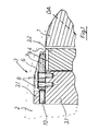
- Fig. 1 shows a part of the plate cylinder 1 assigned to the pressure start DA with the pit 2 and the clamping rail 3 assigned in the pressure start DA.
- the clamping rail 3 consists of an upper clamping rail 3.1 fixedly mounted on the bottom of the pit 2 and one movable relative thereto arranged lower clamping rail 3.2.
- the lower clamping rail 3.2 can be moved relative to the upper clamping rail 3.1 by means of a lifting mechanism, not shown here and known from the prior art, for example.
- the receiving gap 4 is opened for the insertion of a pressure plate 5. If the lower clamping rail 3.2 is set against the upper clamping rail 3.1 with force, that is to say the receiving gap 4 is closed, the inserted pressure plate 5 is clamped.
- FIG. 2 shows a top view of the clamping rail 3 or the upper clamping rail 3.1 according to FIG. 1. Above the clamping rail 3, the edge area of the printing plate 5 associated with the start of printing DA (FIG. 1) is shown.
- the pressure plate 5 has two punched-outs 5.1 with a U-shaped shape in its front edge.
- two groove-shaped recesses 6 are milled into the upper clamping rail 3.1. As can be seen in FIG. 2, the cutouts 6 are additionally widened in the part of the upper clamping rail 3.1 which projects beyond the lower clamping rail 3.2. The bottom of this groove-shaped recess 6 is lower than the upper surface of the lower clamping surface 3.2 when the lower clamping rail 3.2 is lowered or when the receiving gap 4 is fully open.
- a stop in the form of a plate 7 is inserted in each of the two groove-shaped recesses 6 of the upper clamping rail 3.1.
- the end of the stop 7 facing the leading edge of the pressure plate 5 is adapted to the punched areas 5.1 in the pressure plate 5 in accordance with the provided register system in such a way that an optimal register-correct system results.
- each stop 7 is fastened to the upper clamping rail 3.1 via two fastening screws 8 in the respective recess 6.
- the stops 7 each have two through holes, which are dimensioned in such a diameter that there is a sufficiently large degree of mobility with respect to the shanks of the fastening screws 8 (for example hexagon socket screws), so that the stops 7 can be adjusted relative to the pressure start DA.
- the opposite side walls of the recess 6 advantageously have such a fit with respect to the corresponding flanks of the stop 7, so that the respective stop 7 can be moved almost without tilting towards the start of the pressure DA or away from it when the fastening screws 8 are loosened.
- the rounded end of the respective stop 7 facing the pressure plate 5 functions as a dowel pin which interacts with the pressure plate 5 with a punched-out 5.1.
- the lower clamping rail 3.2 Since the underside of the stops 7 rests on the bottom of the recess 6 and, as provided, this lies somewhat lower than the upper side of the lower clamping rail 3.2 in the fully open position, the lower clamping rail 3.2 has a groove 9 in the region of the stops 7, which allows the receiving gap 4 to be closed.
- a plurality of stops 7 of different lengths (based on the distance between the foremost bore and the end of the stop 7) and with differently shaped roundings, which interact with differently shaped punched-outs 5.1 and pressure plates 5, can be provided.
- a particularly preferred embodiment of the invention results when an adjustment means is assigned to the stop 7, by means of which a precise displacement (fastening screws 8 loosened) results within the groove-shaped recess 6.
- the adjusting means can be a threaded bolt 10 (grub screw) screwed into a threaded bore, which can be actuated, for example, by means of a tool in the pit 2, and onto the end of the end facing away from the pressure plate 5 impact 7 acts.
- spring means not shown, can be provided, by means of which the stop 7 is pressed onto the threaded bolt 10.
Applications Claiming Priority (2)
| Application Number | Priority Date | Filing Date | Title |
|---|---|---|---|
| DE9215069U DE9215069U1 (fr) | 1992-11-05 | 1992-11-05 | |
| DE9215069U | 1992-11-05 |
Publications (3)
| Publication Number | Publication Date |
|---|---|
| EP0596337A1 true EP0596337A1 (fr) | 1994-05-11 |
| EP0596337B1 EP0596337B1 (fr) | 1996-04-24 |
| EP0596337B2 EP0596337B2 (fr) | 2000-08-23 |
Family
ID=6885702
Family Applications (1)
| Application Number | Title | Priority Date | Filing Date |
|---|---|---|---|
| EP93117059A Expired - Lifetime EP0596337B2 (fr) | 1992-11-05 | 1993-10-21 | Dispositif pour placer en répérage des plaques d'impression sur des cylindres de plaque des machines |
Country Status (5)
| Country | Link |
|---|---|
| US (1) | US5370051A (fr) |
| EP (1) | EP0596337B2 (fr) |
| JP (1) | JP2609050B2 (fr) |
| AT (1) | ATE137170T1 (fr) |
| DE (2) | DE9215069U1 (fr) |
Cited By (3)
| Publication number | Priority date | Publication date | Assignee | Title |
|---|---|---|---|---|
| US5903073A (en) * | 1996-08-09 | 1999-05-11 | Denso Corporation | Electric rotary machine heat conductive member |
| EP1029670A1 (fr) * | 1999-02-18 | 2000-08-23 | MAN Roland Druckmaschinen AG | Dispositif pour mettre en biais des plaques d'impression sur le cylindre porte-plaque de machines à imprimer |
| EP1182036A1 (fr) * | 2000-08-25 | 2002-02-27 | Heidelberger Druckmaschinen Aktiengesellschaft | Dispositif pour réglage d'au moins un élément de repérage dans une machine d'impression et procédé correspondant |
Families Citing this family (12)
| Publication number | Priority date | Publication date | Assignee | Title |
|---|---|---|---|---|
| DE4306237A1 (de) * | 1993-02-27 | 1994-09-01 | Heidelberger Druckmasch Ag | Einrichtung zur Einstellung des Schrägregisters in einer Spanneinrichtung zum Einspannen von Druckplatten in einer Offsetdruckmaschine |
| DE4340052C2 (de) * | 1993-11-24 | 1996-06-13 | Roland Man Druckmasch | Vorrichtung zur Kontrolle der registergerechten Anlage einer Druckplatte auf einem Plattenzylinder einer Druckmaschine |
| DE9418049U1 (de) | 1994-11-11 | 1994-12-22 | Roland Man Druckmasch | Vorrichtung für das registergerechte Anlegen von Druckplatten |
| IL120138A (en) * | 1997-02-03 | 2001-07-24 | Creoscitex Corp Ltd | A method of recording a rectangular figure |
| US6058838A (en) * | 1997-04-16 | 2000-05-09 | Hirakawa Kogyo Sha Co., Ltd. | Machine plate fastening means, plate cylinder fitted with said fastening means, and offset printing machine equipped with said plate cylinder |
| US6299572B1 (en) * | 1998-01-26 | 2001-10-09 | Credscitex Corporation Ltd. | Print image positioning |
| DE19803723A1 (de) * | 1998-01-30 | 1999-08-05 | Heidelberger Druckmasch Ag | Verfahren und Vorrichtung zur registergenauen Vorpositionierung einer Druckplatte |
| US5915303A (en) * | 1998-02-17 | 1999-06-29 | Goss Graphic Systems, Inc. | Spring clip plate retainer |
| JP2000094642A (ja) * | 1998-09-21 | 2000-04-04 | Ryobi Ltd | 印刷機の刷版取り付け補助装置 |
| DE19950605A1 (de) * | 1999-10-21 | 2001-04-26 | Heidelberger Druckmasch Ag | Gummituch mit Registerausnehmungen und Verfahren zur Gummituchausrichtung |
| US6443065B1 (en) * | 2000-05-17 | 2002-09-03 | Heidelberger Druckmaschinen Ag | Plate cylinder, external plate register tool, and method of registering plates |
| DE102007039824B4 (de) * | 2007-08-23 | 2009-05-20 | Manroland Ag | Registerstegeinrichtung für eine Bogendruckmaschine |
Citations (5)
| Publication number | Priority date | Publication date | Assignee | Title |
|---|---|---|---|---|
| US3858512A (en) * | 1973-03-22 | 1975-01-07 | Roland Offsetmaschf | Lock-up mechanism for flexible printing plates providing improved reference adjustment |
| GB2170785A (en) * | 1985-02-09 | 1986-08-13 | Miller Johannisberg Druckmasch | A sheet printing machine |
| EP0229892A2 (fr) * | 1985-12-20 | 1987-07-29 | M.A.N.-ROLAND Druckmaschinen Aktiengesellschaft | Cylindre de plaque avec dispositif de repérage latéral réglable |
| EP0412720A2 (fr) * | 1989-08-09 | 1991-02-13 | Crabtree Of Gateshead Limited | Procédé et dispositif à imprimer sur des plaques métalliques |
| DE4038920C1 (fr) * | 1990-12-06 | 1992-01-16 | Koenig & Bauer Ag, 8700 Wuerzburg, De |
Family Cites Families (14)
| Publication number | Priority date | Publication date | Assignee | Title |
|---|---|---|---|---|
| US2621592A (en) * | 1947-12-26 | 1952-12-16 | Time Inc | Plate clamp for plate cylinder of printing presses |
| US3882775A (en) * | 1973-07-02 | 1975-05-13 | World Color Press | Registration system for thin magnetic printing plates |
| US3899972A (en) * | 1973-08-27 | 1975-08-19 | William H Albright | Registration-adjusting printing plate saddle |
| US3835778A (en) * | 1973-09-14 | 1974-09-17 | Register Syst Gmbh | Device for attaching and adjusting flexible printing plates on printing cylinders |
| DD116426A1 (fr) † | 1974-11-06 | 1975-11-20 | ||
| DE3000576A1 (de) * | 1980-01-09 | 1981-07-16 | Grapho-Metronic Meß- und Regeltechnik GmbH & Co, KG, 8000 München | Registersystem fuer druckmaschinen |
| DE3138865C2 (de) † | 1981-09-30 | 1983-12-29 | Grapho Metronic Meß- und Regeltechnik GmbH & Co KG, 8000 München | Vorrichtung zur Kontrolle des registergenauen Aufspannens von Druckplatten auf dem Plattenzylinder einer Offset-Druckmaschine |
| JPS6063165A (ja) * | 1983-09-16 | 1985-04-11 | Komori Printing Mach Co Ltd | 枚葉輪転印刷機の刷版装着装置 |
| DE3345369A1 (de) * | 1983-12-15 | 1985-06-27 | M.A.N.- Roland Druckmaschinen AG, 6050 Offenbach | Einrichtung zur befestigung einer druckplatte am plattenzylinder einer druckmaschine |
| JPS62221541A (ja) * | 1986-03-25 | 1987-09-29 | Mitsubishi Heavy Ind Ltd | 自動刷版装着装置 |
| US5016531A (en) † | 1989-01-19 | 1991-05-21 | Hercules, Incorporated | Double truck printing registration system for a rotary printing press |
| DE3940796A1 (de) * | 1989-12-09 | 1991-06-13 | Koenig & Bauer Ag | Verfahren und einrichtung zum automatischen wechseln einer druckplatte |
| DE4129831C3 (de) * | 1990-12-21 | 1998-08-13 | Heidelberger Druckmasch Ag | Schnellklemmvorrichtung |
| DE19508438C1 (de) * | 1995-03-09 | 1995-11-23 | Hanses & Co Kg | Sortierboxensystem für Schnittholz oder vergleichbares Gut |
-
1992
- 1992-11-05 DE DE9215069U patent/DE9215069U1/de not_active Expired - Lifetime
-
1993
- 1993-10-21 EP EP93117059A patent/EP0596337B2/fr not_active Expired - Lifetime
- 1993-10-21 DE DE59302354T patent/DE59302354D1/de not_active Expired - Lifetime
- 1993-10-21 AT AT93117059T patent/ATE137170T1/de not_active IP Right Cessation
- 1993-11-02 JP JP5274166A patent/JP2609050B2/ja not_active Expired - Fee Related
- 1993-11-03 US US08/147,159 patent/US5370051A/en not_active Expired - Fee Related
Patent Citations (5)
| Publication number | Priority date | Publication date | Assignee | Title |
|---|---|---|---|---|
| US3858512A (en) * | 1973-03-22 | 1975-01-07 | Roland Offsetmaschf | Lock-up mechanism for flexible printing plates providing improved reference adjustment |
| GB2170785A (en) * | 1985-02-09 | 1986-08-13 | Miller Johannisberg Druckmasch | A sheet printing machine |
| EP0229892A2 (fr) * | 1985-12-20 | 1987-07-29 | M.A.N.-ROLAND Druckmaschinen Aktiengesellschaft | Cylindre de plaque avec dispositif de repérage latéral réglable |
| EP0412720A2 (fr) * | 1989-08-09 | 1991-02-13 | Crabtree Of Gateshead Limited | Procédé et dispositif à imprimer sur des plaques métalliques |
| DE4038920C1 (fr) * | 1990-12-06 | 1992-01-16 | Koenig & Bauer Ag, 8700 Wuerzburg, De |
Cited By (4)
| Publication number | Priority date | Publication date | Assignee | Title |
|---|---|---|---|---|
| US5903073A (en) * | 1996-08-09 | 1999-05-11 | Denso Corporation | Electric rotary machine heat conductive member |
| EP1029670A1 (fr) * | 1999-02-18 | 2000-08-23 | MAN Roland Druckmaschinen AG | Dispositif pour mettre en biais des plaques d'impression sur le cylindre porte-plaque de machines à imprimer |
| EP1182036A1 (fr) * | 2000-08-25 | 2002-02-27 | Heidelberger Druckmaschinen Aktiengesellschaft | Dispositif pour réglage d'au moins un élément de repérage dans une machine d'impression et procédé correspondant |
| US6748862B2 (en) | 2000-08-25 | 2004-06-15 | Heidelberger Druckmaschinen Ag | Device for adjusting at least one register element in a printing machine, and corresponding method |
Also Published As
| Publication number | Publication date |
|---|---|
| JP2609050B2 (ja) | 1997-05-14 |
| EP0596337B1 (fr) | 1996-04-24 |
| JPH06198848A (ja) | 1994-07-19 |
| DE9215069U1 (fr) | 1992-12-17 |
| ATE137170T1 (de) | 1996-05-15 |
| EP0596337B2 (fr) | 2000-08-23 |
| DE59302354D1 (de) | 1996-05-30 |
| US5370051A (en) | 1994-12-06 |
Similar Documents
| Publication | Publication Date | Title |
|---|---|---|
| EP0596337B1 (fr) | Dispositif pour placer en répérage des plaques d'impression sur des cylindres de plaque des machines | |
| EP0238804B1 (fr) | Dispositif de fixation des clichés souples sur les cylindres de clichés dans les rotatives | |
| DE19634343A1 (de) | Spanneinrichtung für Zugmittel mit festgelegtem Spannweg | |
| DE3516682C2 (fr) | ||
| EP0613777B1 (fr) | Dispositif pour ajuster le registre oblique dans un dispositif de serrage pour tendre des plaques d'impression dans une machine d'impression offset | |
| DE4444062C2 (de) | Vorrichtung zum Ausrichten einer Druckplatte auf einem Plattenzylinder einer Rotationsdruckmaschine | |
| EP0631868B1 (fr) | Dispositif pour tendre en repérage des plaques d'impression sur les cylindres de machines d'impression | |
| DE3936459C1 (fr) | ||
| EP0655331B1 (fr) | Dispositif pour contrÔler le positionnement en registre de plaques sur le cylindre porte-plaque de machines à imprimer | |
| EP0727311A1 (fr) | Dispositif pour échanger des plaques d'impression | |
| EP1182036B1 (fr) | Dispositif pour réglage d'au moins un élément de repérage dans une machine d'impression et procédé correspondant | |
| EP0756919A1 (fr) | Dispositif pour poinçonner un matériau en forme de bande ou feuille | |
| EP0429808B1 (fr) | Dispositif pour tendre avec un repérage exact une plaque d'impression sur un cylindre d'impression | |
| EP0635367B1 (fr) | Dispositif de positionnement de clichés sur le cylindre porte-plaque d'une machine d'impression | |
| DE19701955C2 (de) | Befestigungsvorrichtung für Druckformen | |
| EP0534214B1 (fr) | Procédé et dispositif pour la correction de divergences trapézoidales des repères | |
| DE4410385C2 (de) | Vorrichtung zum Befestigen von Druckplatten | |
| DE4226192C2 (de) | Verfahren und Vorrichtung zur Korrektur trapezartiger Passerabweichungen | |
| DE4240462C2 (de) | Vorrichtung zum registergenauen Aufspannen von Druckplatten auf dem Plattenzylinder von Druckmaschinen | |
| DE4314436C2 (de) | Spannschiene für den Plattenzylinder einer Druckmaschine, insbesondere Bogenoffsetdruckmaschine | |
| EP0875378A1 (fr) | Dispositif de serrage | |
| DE10004203A1 (de) | Befestigungsleiste zum Befestigen einer Druckplattenhinterkante | |
| DE7500180U (de) | Vorrichtung zum einspannen von an ihren einspannraendern passlochungen aufweisenden druckplatten in offset-maschinen |
Legal Events
| Date | Code | Title | Description |
|---|---|---|---|
| PUAI | Public reference made under article 153(3) epc to a published international application that has entered the european phase |
Free format text: ORIGINAL CODE: 0009012 |
|
| 17P | Request for examination filed |
Effective date: 19931103 |
|
| AK | Designated contracting states |
Kind code of ref document: A1 Designated state(s): AT BE CH DE DK ES FR GB GR IE IT LI LU NL PT SE |
|
| 17Q | First examination report despatched |
Effective date: 19950828 |
|
| ITF | It: translation for a ep patent filed |
Owner name: DE DOMINICIS & MAYER S.R.L. |
|
| GRAA | (expected) grant |
Free format text: ORIGINAL CODE: 0009210 |
|
| AK | Designated contracting states |
Kind code of ref document: B1 Designated state(s): AT BE CH DE DK ES FR GB GR IE IT LI LU NL PT SE |
|
| PG25 | Lapsed in a contracting state [announced via postgrant information from national office to epo] |
Ref country code: GR Free format text: LAPSE BECAUSE OF FAILURE TO SUBMIT A TRANSLATION OF THE DESCRIPTION OR TO PAY THE FEE WITHIN THE PRESCRIBED TIME-LIMIT Effective date: 19960424 Ref country code: ES Free format text: THE PATENT HAS BEEN ANNULLED BY A DECISION OF A NATIONAL AUTHORITY Effective date: 19960424 Ref country code: DK Effective date: 19960424 |
|
| REF | Corresponds to: |
Ref document number: 137170 Country of ref document: AT Date of ref document: 19960515 Kind code of ref document: T |
|
| REG | Reference to a national code |
Ref country code: CH Ref legal event code: NV Representative=s name: E. BLUM & CO. PATENTANWAELTE |
|
| ET | Fr: translation filed | ||
| REG | Reference to a national code |
Ref country code: IE Ref legal event code: FG4D Free format text: 68117 |
|
| GBT | Gb: translation of ep patent filed (gb section 77(6)(a)/1977) |
Effective date: 19960429 |
|
| REF | Corresponds to: |
Ref document number: 59302354 Country of ref document: DE Date of ref document: 19960530 |
|
| PG25 | Lapsed in a contracting state [announced via postgrant information from national office to epo] |
Ref country code: PT Effective date: 19960724 |
|
| PG25 | Lapsed in a contracting state [announced via postgrant information from national office to epo] |
Ref country code: LU Free format text: LAPSE BECAUSE OF NON-PAYMENT OF DUE FEES Effective date: 19961031 |
|
| PG25 | Lapsed in a contracting state [announced via postgrant information from national office to epo] |
Ref country code: IE Free format text: LAPSE BECAUSE OF NON-PAYMENT OF DUE FEES Effective date: 19961107 |
|
| REG | Reference to a national code |
Ref country code: IE Ref legal event code: FD4D Ref document number: 68117 Country of ref document: IE |
|
| PLBQ | Unpublished change to opponent data |
Free format text: ORIGINAL CODE: EPIDOS OPPO |
|
| PLBI | Opposition filed |
Free format text: ORIGINAL CODE: 0009260 |
|
| PLBF | Reply of patent proprietor to notice(s) of opposition |
Free format text: ORIGINAL CODE: EPIDOS OBSO |
|
| 26 | Opposition filed |
Opponent name: KBA - PLANETA AG Effective date: 19970122 Opponent name: HEIDELBERGER DRUCKMASCHINEN AG Effective date: 19970122 |
|
| NLR1 | Nl: opposition has been filed with the epo |
Opponent name: KBA - PLANETA AG Opponent name: HEIDELBERGER DRUCKMASCHINEN AG |
|
| PLBF | Reply of patent proprietor to notice(s) of opposition |
Free format text: ORIGINAL CODE: EPIDOS OBSO |
|
| PLAW | Interlocutory decision in opposition |
Free format text: ORIGINAL CODE: EPIDOS IDOP |
|
| APAC | Appeal dossier modified |
Free format text: ORIGINAL CODE: EPIDOS NOAPO |
|
| APAE | Appeal reference modified |
Free format text: ORIGINAL CODE: EPIDOS REFNO |
|
| APAC | Appeal dossier modified |
Free format text: ORIGINAL CODE: EPIDOS NOAPO |
|
| APAC | Appeal dossier modified |
Free format text: ORIGINAL CODE: EPIDOS NOAPO |
|
| PLAW | Interlocutory decision in opposition |
Free format text: ORIGINAL CODE: EPIDOS IDOP |
|
| PUAH | Patent maintained in amended form |
Free format text: ORIGINAL CODE: 0009272 |
|
| STAA | Information on the status of an ep patent application or granted ep patent |
Free format text: STATUS: PATENT MAINTAINED AS AMENDED |
|
| 27A | Patent maintained in amended form |
Effective date: 20000823 |
|
| AK | Designated contracting states |
Kind code of ref document: B2 Designated state(s): AT BE CH DE DK ES FR GB GR IE IT LI LU NL PT SE |
|
| ET3 | Fr: translation filed ** decision concerning opposition | ||
| REG | Reference to a national code |
Ref country code: CH Ref legal event code: AEN Free format text: AUFRECHTERHALTUNG DES PATENTES IN GEAENDERTER FORM |
|
| NLR2 | Nl: decision of opposition | ||
| ITF | It: translation for a ep patent filed |
Owner name: DE DOMINICIS & MAYER S.R.L. |
|
| GBTA | Gb: translation of amended ep patent filed (gb section 77(6)(b)/1977) | ||
| NLR3 | Nl: receipt of modified translations in the netherlands language after an opposition procedure | ||
| REG | Reference to a national code |
Ref country code: GB Ref legal event code: IF02 |
|
| PGFP | Annual fee paid to national office [announced via postgrant information from national office to epo] |
Ref country code: CH Payment date: 20020918 Year of fee payment: 10 |
|
| PGFP | Annual fee paid to national office [announced via postgrant information from national office to epo] |
Ref country code: GB Payment date: 20020925 Year of fee payment: 10 |
|
| PGFP | Annual fee paid to national office [announced via postgrant information from national office to epo] |
Ref country code: BE Payment date: 20020926 Year of fee payment: 10 |
|
| PGFP | Annual fee paid to national office [announced via postgrant information from national office to epo] |
Ref country code: NL Payment date: 20020930 Year of fee payment: 10 |
|
| PGFP | Annual fee paid to national office [announced via postgrant information from national office to epo] |
Ref country code: SE Payment date: 20021002 Year of fee payment: 10 |
|
| PGFP | Annual fee paid to national office [announced via postgrant information from national office to epo] |
Ref country code: AT Payment date: 20021003 Year of fee payment: 10 |
|
| PGFP | Annual fee paid to national office [announced via postgrant information from national office to epo] |
Ref country code: FR Payment date: 20021009 Year of fee payment: 10 |
|
| PG25 | Lapsed in a contracting state [announced via postgrant information from national office to epo] |
Ref country code: GB Free format text: LAPSE BECAUSE OF NON-PAYMENT OF DUE FEES Effective date: 20031021 Ref country code: AT Free format text: LAPSE BECAUSE OF NON-PAYMENT OF DUE FEES Effective date: 20031021 |
|
| PG25 | Lapsed in a contracting state [announced via postgrant information from national office to epo] |
Ref country code: SE Free format text: LAPSE BECAUSE OF NON-PAYMENT OF DUE FEES Effective date: 20031022 |
|
| PG25 | Lapsed in a contracting state [announced via postgrant information from national office to epo] |
Ref country code: LI Free format text: LAPSE BECAUSE OF NON-PAYMENT OF DUE FEES Effective date: 20031031 Ref country code: CH Free format text: LAPSE BECAUSE OF NON-PAYMENT OF DUE FEES Effective date: 20031031 Ref country code: BE Free format text: LAPSE BECAUSE OF NON-PAYMENT OF DUE FEES Effective date: 20031031 |
|
| BERE | Be: lapsed |
Owner name: *MAN ROLAND DRUCKMASCHINEN A.G. Effective date: 20031031 |
|
| PG25 | Lapsed in a contracting state [announced via postgrant information from national office to epo] |
Ref country code: NL Free format text: LAPSE BECAUSE OF NON-PAYMENT OF DUE FEES Effective date: 20040501 |
|
| EUG | Se: european patent has lapsed | ||
| GBPC | Gb: european patent ceased through non-payment of renewal fee |
Effective date: 20031021 |
|
| REG | Reference to a national code |
Ref country code: CH Ref legal event code: PL |
|
| PG25 | Lapsed in a contracting state [announced via postgrant information from national office to epo] |
Ref country code: FR Free format text: LAPSE BECAUSE OF NON-PAYMENT OF DUE FEES Effective date: 20040630 |
|
| NLV4 | Nl: lapsed or anulled due to non-payment of the annual fee |
Effective date: 20040501 |
|
| REG | Reference to a national code |
Ref country code: FR Ref legal event code: ST |
|
| APAH | Appeal reference modified |
Free format text: ORIGINAL CODE: EPIDOSCREFNO |
|
| PG25 | Lapsed in a contracting state [announced via postgrant information from national office to epo] |
Ref country code: IT Free format text: LAPSE BECAUSE OF NON-PAYMENT OF DUE FEES;WARNING: LAPSES OF ITALIAN PATENTS WITH EFFECTIVE DATE BEFORE 2007 MAY HAVE OCCURRED AT ANY TIME BEFORE 2007. THE CORRECT EFFECTIVE DATE MAY BE DIFFERENT FROM THE ONE RECORDED. Effective date: 20051021 |
|
| PGFP | Annual fee paid to national office [announced via postgrant information from national office to epo] |
Ref country code: DE Payment date: 20091026 Year of fee payment: 17 |
|
| REG | Reference to a national code |
Ref country code: DE Ref legal event code: R119 Ref document number: 59302354 Country of ref document: DE Effective date: 20110502 |
|
| PG25 | Lapsed in a contracting state [announced via postgrant information from national office to epo] |
Ref country code: DE Free format text: LAPSE BECAUSE OF NON-PAYMENT OF DUE FEES Effective date: 20110502 |