EP0593398A1 - Kombination von Treibrolle und Scheren - Google Patents
Kombination von Treibrolle und Scheren Download PDFInfo
- Publication number
- EP0593398A1 EP0593398A1 EP93810708A EP93810708A EP0593398A1 EP 0593398 A1 EP0593398 A1 EP 0593398A1 EP 93810708 A EP93810708 A EP 93810708A EP 93810708 A EP93810708 A EP 93810708A EP 0593398 A1 EP0593398 A1 EP 0593398A1
- Authority
- EP
- European Patent Office
- Prior art keywords
- shear
- carriage
- roll
- combination
- pinch roll
- Prior art date
- Legal status (The legal status is an assumption and is not a legal conclusion. Google has not performed a legal analysis and makes no representation as to the accuracy of the status listed.)
- Withdrawn
Links
- 238000005096 rolling process Methods 0.000 claims description 19
- 239000000463 material Substances 0.000 claims description 12
- 230000008878 coupling Effects 0.000 claims 1
- 238000010168 coupling process Methods 0.000 claims 1
- 238000005859 coupling reaction Methods 0.000 claims 1
- 229910000831 Steel Inorganic materials 0.000 description 3
- 239000010959 steel Substances 0.000 description 3
- 238000011144 upstream manufacturing Methods 0.000 description 3
- 238000010008 shearing Methods 0.000 description 2
- 238000000034 method Methods 0.000 description 1
- 238000012986 modification Methods 0.000 description 1
- 230000004048 modification Effects 0.000 description 1
Images

Classifications
-
- B—PERFORMING OPERATIONS; TRANSPORTING
- B23—MACHINE TOOLS; METAL-WORKING NOT OTHERWISE PROVIDED FOR
- B23D—PLANING; SLOTTING; SHEARING; BROACHING; SAWING; FILING; SCRAPING; LIKE OPERATIONS FOR WORKING METAL BY REMOVING MATERIAL, NOT OTHERWISE PROVIDED FOR
- B23D17/00—Shearing machines or shearing devices cutting by blades pivoted on a single axis
- B23D17/02—Shearing machines or shearing devices cutting by blades pivoted on a single axis characterised by drives or gearings therefor
-
- B—PERFORMING OPERATIONS; TRANSPORTING
- B21—MECHANICAL METAL-WORKING WITHOUT ESSENTIALLY REMOVING MATERIAL; PUNCHING METAL
- B21B—ROLLING OF METAL
- B21B1/00—Metal-rolling methods or mills for making semi-finished products of solid or profiled cross-section; Sequence of operations in milling trains; Layout of rolling-mill plant, e.g. grouping of stands; Succession of passes or of sectional pass alternations
- B21B1/22—Metal-rolling methods or mills for making semi-finished products of solid or profiled cross-section; Sequence of operations in milling trains; Layout of rolling-mill plant, e.g. grouping of stands; Succession of passes or of sectional pass alternations for rolling plates, strips, bands or sheets of indefinite length
- B21B1/30—Metal-rolling methods or mills for making semi-finished products of solid or profiled cross-section; Sequence of operations in milling trains; Layout of rolling-mill plant, e.g. grouping of stands; Succession of passes or of sectional pass alternations for rolling plates, strips, bands or sheets of indefinite length in a non-continuous process
- B21B1/32—Metal-rolling methods or mills for making semi-finished products of solid or profiled cross-section; Sequence of operations in milling trains; Layout of rolling-mill plant, e.g. grouping of stands; Succession of passes or of sectional pass alternations for rolling plates, strips, bands or sheets of indefinite length in a non-continuous process in reversing single stand mills, e.g. with intermediate storage reels for accumulating work
- B21B1/34—Metal-rolling methods or mills for making semi-finished products of solid or profiled cross-section; Sequence of operations in milling trains; Layout of rolling-mill plant, e.g. grouping of stands; Succession of passes or of sectional pass alternations for rolling plates, strips, bands or sheets of indefinite length in a non-continuous process in reversing single stand mills, e.g. with intermediate storage reels for accumulating work by hot-rolling
-
- B—PERFORMING OPERATIONS; TRANSPORTING
- B21—MECHANICAL METAL-WORKING WITHOUT ESSENTIALLY REMOVING MATERIAL; PUNCHING METAL
- B21B—ROLLING OF METAL
- B21B15/00—Arrangements for performing additional metal-working operations specially combined with or arranged in, or specially adapted for use in connection with, metal-rolling mills
- B21B15/0007—Cutting or shearing the product
-
- B—PERFORMING OPERATIONS; TRANSPORTING
- B21—MECHANICAL METAL-WORKING WITHOUT ESSENTIALLY REMOVING MATERIAL; PUNCHING METAL
- B21B—ROLLING OF METAL
- B21B39/00—Arrangements for moving, supporting, or positioning work, or controlling its movement, combined with or arranged in, or specially adapted for use in connection with, metal-rolling mills
- B21B39/006—Pinch roll sets
-
- B—PERFORMING OPERATIONS; TRANSPORTING
- B23—MACHINE TOOLS; METAL-WORKING NOT OTHERWISE PROVIDED FOR
- B23D—PLANING; SLOTTING; SHEARING; BROACHING; SAWING; FILING; SCRAPING; LIKE OPERATIONS FOR WORKING METAL BY REMOVING MATERIAL, NOT OTHERWISE PROVIDED FOR
- B23D17/00—Shearing machines or shearing devices cutting by blades pivoted on a single axis
- B23D17/02—Shearing machines or shearing devices cutting by blades pivoted on a single axis characterised by drives or gearings therefor
- B23D17/06—Shearing machines or shearing devices cutting by blades pivoted on a single axis characterised by drives or gearings therefor actuated by fluid or gas pressure
-
- B—PERFORMING OPERATIONS; TRANSPORTING
- B23—MACHINE TOOLS; METAL-WORKING NOT OTHERWISE PROVIDED FOR
- B23D—PLANING; SLOTTING; SHEARING; BROACHING; SAWING; FILING; SCRAPING; LIKE OPERATIONS FOR WORKING METAL BY REMOVING MATERIAL, NOT OTHERWISE PROVIDED FOR
- B23D33/00—Accessories for shearing machines or shearing devices
- B23D33/08—Press-pads; Counter-bases; Hold-down devices
-
- B—PERFORMING OPERATIONS; TRANSPORTING
- B21—MECHANICAL METAL-WORKING WITHOUT ESSENTIALLY REMOVING MATERIAL; PUNCHING METAL
- B21B—ROLLING OF METAL
- B21B1/00—Metal-rolling methods or mills for making semi-finished products of solid or profiled cross-section; Sequence of operations in milling trains; Layout of rolling-mill plant, e.g. grouping of stands; Succession of passes or of sectional pass alternations
- B21B1/02—Metal-rolling methods or mills for making semi-finished products of solid or profiled cross-section; Sequence of operations in milling trains; Layout of rolling-mill plant, e.g. grouping of stands; Succession of passes or of sectional pass alternations for rolling heavy work, e.g. ingots, slabs, blooms, or billets, in which the cross-sectional form is unimportant ; Rolling combined with forging or pressing
- B21B1/06—Metal-rolling methods or mills for making semi-finished products of solid or profiled cross-section; Sequence of operations in milling trains; Layout of rolling-mill plant, e.g. grouping of stands; Succession of passes or of sectional pass alternations for rolling heavy work, e.g. ingots, slabs, blooms, or billets, in which the cross-sectional form is unimportant ; Rolling combined with forging or pressing in a non-continuous process, e.g. triplet mill, reversing mill
-
- B—PERFORMING OPERATIONS; TRANSPORTING
- B21—MECHANICAL METAL-WORKING WITHOUT ESSENTIALLY REMOVING MATERIAL; PUNCHING METAL
- B21B—ROLLING OF METAL
- B21B1/00—Metal-rolling methods or mills for making semi-finished products of solid or profiled cross-section; Sequence of operations in milling trains; Layout of rolling-mill plant, e.g. grouping of stands; Succession of passes or of sectional pass alternations
- B21B1/22—Metal-rolling methods or mills for making semi-finished products of solid or profiled cross-section; Sequence of operations in milling trains; Layout of rolling-mill plant, e.g. grouping of stands; Succession of passes or of sectional pass alternations for rolling plates, strips, bands or sheets of indefinite length
- B21B2001/225—Metal-rolling methods or mills for making semi-finished products of solid or profiled cross-section; Sequence of operations in milling trains; Layout of rolling-mill plant, e.g. grouping of stands; Succession of passes or of sectional pass alternations for rolling plates, strips, bands or sheets of indefinite length by hot-rolling
Definitions
- This invention relates to a pinch roll and shear combination for use in rolling mills, specifically for use with coilers on hot strip reversing mills.
- a shear In conventional continuous hot mills, a shear is located between the roughing stand or stands and the finishing train. When a hot reversing mill is employed in lieu of the continuous mill or the finishing train, a shear is likewise positioned well upstream of the hot reversing mill. With the advent of the use of coiler furnaces in conjunction with hot reversing mills, the location of the upstream shear has remained constant, with the upstream coiler furnace being downstream of the shear.
- the strip can be additionally trimmed at its leading and trailing ends after the finishing passes by the roll stand.
- the shear unit has been positioned on the pass line adjacent a pinch roll unit which precedes a coiler, as set forth in U.S. Patent Nos. 4,497,191 and 4,494,395.
- Pinch rolls are used in a number of ways on steel processing lines to control speed of travel or tension of steel strip. One such use is in conjunction with coilers. Examples of such pinch rollers are shown in U.S. Patent Nos. 4,497,191; 3,613,426; 4,430,874 and 4,522,050.
- the object of the present invention is to provide a compact, economical and efficient pinch roll and shear combination.
- the present invention provides a pinch roll and shear combination for use in a strip mill, such as in conjunction with a coiler, which forms part of a reversing hot strip mill unit.
- the pinch roll and shear combination of the present invention includes a frame with a lower roll rotatably mounted on the frame, and a stationary lower blade mounted on the frame adjacent the lower roll.
- a movable carriage is mounted on the frame for rectilinear motion.
- a hydraulic cylinder is attached to the frame for moving the carriage.
- An upper roll is rotatably mounted on the carriage and cooperates with the lower roll on the frame to form a pinch roll.
- An upper blade assembly is mounted on the carriage, with the upper blade assembly adapted for reciprocating an upper blade relative to the carriage.
- An upper blade carried on the upper blade assembly cooperates with the lower blade to form a shear.
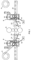
- Fig. 1 illustrates a hot strip mill which includes a rolling mill 10, shown as a four-high rolling mill, for reducing a slab of material to be worked on.
- a pair of coiler furnaces 12 and 14 are provided on opposite sides of the rolling mill 10 with each coiler furnace adapted to coil the material to be worked on after passing through the rolling mill 10.
- a pair of pinch roll and shear combinations 16 and 18 are provided on opposite sides of the rolling mill 10 adjacent the openings of the coiler furnaces 12 and 14.
- a pair of crop removal deflectors 22 and 24 are pivotally coupled to the roller table 20.
- the crop removal deflectors 22 and 24 are positioned immediately adjacent the pinch roll and shear combinations 16 and 18, respectively.
- Pistons 26 and 28 are mounted to the roller table 20 and operate to pivot the crop removal deflectors 22 and 24, respectively.
- Guide plates 30 and 32 extend between a pinch roll and shear combination 16 or 18, and a crop removal bin 34 or 36, respectively, positioned below the respective pinch roll and shear combination.
- the pinch roll and shear combination is best illustrated in Fig. 2.
- the pinch roll and shear combination 16 includes a frame 38 upon which a lower roll 40 is rotatably mounted.
- a stationary lower blade 42 is mounted on the frame 38 adjacent the rotatable lower roll 40.
- a rectilinearly movable carriage 44 is mounted within the frame 38.
- a hydraulic cylinder 46 is attached to the frame 38 and coupled to the carriage 44. The hydraulic cylinder 46 is adapted to move the carriage 44 in a rectilinear manner.
- An upper roll 48 is rotatably mounted on the carriage 44 and is aligned with the lower roll 40 such as to form a pinch roll.
- An upper blade assembly 50 is mounted on the carriage 44 and is aligned with the lower blade 42 to form a shear.
- the upper blade assembly 50 includes a pivotable linkage assembly 52 which attaches an upper blade 54 to the carriage 44.
- a hydraulic cylinder 56 is mounted to the carriage 44 and coupled to the linkage assembly 52. The cylinder 56 operates to pivot the linkage assembly 52 which in turn rectilinearly moves the upper blade 54 relative to the carriage 44.
- the upper blade 54 includes a hold-down bar 58 which is positioned vertically above the lower blade 42 and adjacent the upper blade 54.
- the pinch roll and shear combination 16 and 18 of the present invention provide a compact, economical and efficient pinch roll and shear device for use in rolling mills.
- a slab of material to be worked upon such as the steel slab 60 shown in Fig. 1
- Each pass of the slab 60 through the rolling mill 10 reduces the thickness of the slab 60.
- the slab is reduced to a point until it can be coiled, at which time it will be coiled in one of the two coiler furnaces 12 and 14.
- the coiled material will be passed from one coiler furnace to the other through the rolling mill 10 until the desired, finished product is obtained.
- the pinch rolls of the pinch roll and shear combination will be utilized in the conventional fashion to move the material in and out of the coilers and through the rolling mill.
- the shears of the pinch roll and shear combination can be utilized on the workpiece at any time throughout the process.
- the shears may be utilized to crop the leading and trailing ends of the material being worked upon after the final pass through the rolling mill 10.
- the shears may also be utilized to provide a clean leading edge in the middle of the rolling process.
- the pinch roll of the present invention has been found to work effectively when utilizing an upper roll 48 which has a diameter larger than the diameter of the lower roll 40.
- a 24'' diameter upper roll has been utilized with an 18'' diameter lower roll 40.
- the carriage 44 is provided with a sufficient range of motion to allow the upper roll 48 to be moved completely out of the way (e.g. a 'high pass').
- a 14'' stroke for the hydraulic cylinder 46 provides sufficient range of motion for the carriage 44.
- the present invention may also provide an improved shearing action for cropping the workpiece.
- the compact arrangement of the present invention allows the lower blade 42 to be positioned closely adjacent the lower roll 40. For example, when an 18'' diameter lower roll 40 is utilized, the cutting line 62 formed by the shear is about 20'' from the center line of the lower roll 40. This close proximity may improve the quality of the cut being performed. While a material is being sheared between cooperating blades 42 and 54, it is being held between the pinch rolls 40 and 48 immediately adjacent the cutting line 62. This action will further assist the operation of the hold-down bar 58 in obtaining a smooth shear of the workpiece.
- the present arrangement minimizes the space required for including a shear and pinch roll, as well as minimizing the structural components of these individualized units.
Applications Claiming Priority (2)
| Application Number | Priority Date | Filing Date | Title |
|---|---|---|---|
| US961512 | 1992-10-15 | ||
| US07/961,512 US5285670A (en) | 1992-10-15 | 1992-10-15 | Pinch roll and shear combination |
Publications (1)
| Publication Number | Publication Date |
|---|---|
| EP0593398A1 true EP0593398A1 (de) | 1994-04-20 |
Family
ID=25504572
Family Applications (1)
| Application Number | Title | Priority Date | Filing Date |
|---|---|---|---|
| EP93810708A Withdrawn EP0593398A1 (de) | 1992-10-15 | 1993-10-06 | Kombination von Treibrolle und Scheren |
Country Status (5)
| Country | Link |
|---|---|
| US (1) | US5285670A (de) |
| EP (1) | EP0593398A1 (de) |
| KR (1) | KR960008872B1 (de) |
| CN (1) | CN1087847A (de) |
| CA (1) | CA2108400C (de) |
Cited By (3)
| Publication number | Priority date | Publication date | Assignee | Title |
|---|---|---|---|---|
| EP0860248A2 (de) * | 1997-02-25 | 1998-08-26 | Karl Eugen Fischer GmbH Maschinenfabrik | Niederhalter für eine Schere |
| WO2004054730A1 (de) * | 2002-12-14 | 2004-07-01 | Sms Demag Aktiengesellschaft | Verfahren und anlage zum warmwalzen von bändern mit einem steckelwalzgerüst |
| DE102012201418A1 (de) | 2012-02-01 | 2013-08-01 | Sms Siemag Ag | Steckel-Walzwerk |
Families Citing this family (9)
| Publication number | Priority date | Publication date | Assignee | Title |
|---|---|---|---|---|
| US6264767B1 (en) | 1995-06-07 | 2001-07-24 | Ipsco Enterprises Inc. | Method of producing martensite-or bainite-rich steel using steckel mill and controlled cooling |
| US6502445B1 (en) * | 1997-07-15 | 2003-01-07 | Danieli & C. Officine Meccaniche Spa | Coiling machine for hot rolled stock such as strip or sheet and relative coiling method |
| DE10133756A1 (de) * | 2001-07-11 | 2003-01-30 | Sms Demag Ag | Kaltwalzwerk sowie Verfahren zum Kaltwalzen von metallischem Band |
| JP2004050220A (ja) * | 2002-07-18 | 2004-02-19 | Ishikawajima Harima Heavy Ind Co Ltd | 帯板製造設備 |
| UA79184C2 (en) * | 2002-12-14 | 2007-05-25 | Sms Demag Ag | Method and installation for hot-rolling strips using reversible steckel rolling frame |
| DE102004034090A1 (de) * | 2004-07-15 | 2006-02-02 | Sms Demag Ag | Walzanlage zum Walzen metallischen Guts |
| CN104162714A (zh) * | 2014-07-04 | 2014-11-26 | 太原科技大学 | 一种单液压缸驱动滚切式板材剪切机 |
| KR101867679B1 (ko) * | 2016-07-28 | 2018-06-15 | 주식회사 포스코 | 스트립 중앙 위치 제어 장치 |
| CN109834113B (zh) * | 2019-03-25 | 2024-04-26 | 中冶南方工程技术有限公司 | 钢卷准备站中带头处理设备 |
Citations (9)
| Publication number | Priority date | Publication date | Assignee | Title |
|---|---|---|---|---|
| DE404763C (de) * | 1921-12-25 | 1924-10-24 | Schloemann Akt Ges | Vorrichtung zum Schneiden von Walzstaeben |
| US3197992A (en) * | 1963-06-11 | 1965-08-03 | Hitachi Ltd | Slitting apparatus for hoop mills |
| US3613426A (en) * | 1968-11-04 | 1971-10-19 | United Eng Foundry Co | Hot reversing strip mill method and apparatus |
| JPS5677006A (en) * | 1979-11-30 | 1981-06-25 | Mitsubishi Heavy Ind Ltd | Strip mill |
| US4337679A (en) * | 1979-07-02 | 1982-07-06 | Krylov Gleb L | Plate shears |
| US4455848A (en) * | 1982-09-13 | 1984-06-26 | Tippins Machinery Company, Inc. | Apparatus for underwinding strip on a drum in a hot reversing mill |
| JPS59156611A (ja) * | 1983-02-25 | 1984-09-05 | Kobe Steel Ltd | 経路切替機構を備えた剪断機 |
| US4497191A (en) * | 1982-03-05 | 1985-02-05 | Voest-Alpine Aktiengesellschaft | Plant and process for hot-rolling strip or plate stock |
| JPS6076910A (ja) * | 1983-09-30 | 1985-05-01 | Mitsubishi Heavy Ind Ltd | スクラツプシヤ−におけるスクラツプ装入装置 |
Family Cites Families (17)
| Publication number | Priority date | Publication date | Assignee | Title |
|---|---|---|---|---|
| US1918968A (en) * | 1928-01-12 | 1933-07-18 | Robert M Keeney | Rolling mill |
| GB1204817A (en) * | 1967-11-18 | 1970-09-09 | Siemag Siegener Masch Bau | Strip coiler |
| DE2331653B2 (de) * | 1973-06-22 | 1977-05-12 | Meteor-Siegen Apparatebau Paul Schmeck Gmbh, 5900 Siegen | Transport- und abtrenneinrichtung fuer bahnfoermiges kopiermaterial in insbesondere einer lichtpausmaschine |
| US4043494A (en) * | 1976-02-23 | 1977-08-23 | Amp Incorporated | Apparatus for feeding a plurality of wires |
| US4096724A (en) * | 1977-05-27 | 1978-06-27 | General Motors Corporation | Method of coiling a flat strip |
| US4430874A (en) * | 1981-09-29 | 1984-02-14 | Tippins Machinery Company, Inc. | Vertical coiler furnace and method of rolling |
| JPS5873306A (ja) * | 1981-10-23 | 1983-05-02 | ワイケイケイ株式会社 | スライドフアスナ−チエ−ンの切断装置 |
| AT372881B (de) * | 1982-03-05 | 1983-11-25 | Voest Alpine Ag | Anlage zum warmwalzen von band- oder tafelfoermigem walzgut |
| DE3241745C2 (de) * | 1982-11-11 | 1985-08-08 | Mannesmann AG, 4000 Düsseldorf | Verfahren zum Herstellen von warmgewalztem Stahlband aus stranggegossenem Vormaterial in unmittelbar aufeinanderfolgenden Arbeitsschritten |
| US4522050A (en) * | 1983-01-14 | 1985-06-11 | Tippins Machinery Company, Inc. | Three stand mini mill method and apparatus |
| US4675974A (en) * | 1985-10-17 | 1987-06-30 | Tippins Machinery Co., Inc. | Method of continuous casting and rolling strip |
| US4793169A (en) * | 1986-06-27 | 1988-12-27 | United Engineering, Inc. | Continuous backpass rolling mill |
| JPS63252604A (ja) * | 1987-04-08 | 1988-10-19 | Hitachi Ltd | 連鋳直結圧延方法及び装置 |
| JPS63309306A (ja) * | 1987-06-11 | 1988-12-16 | Hitachi Ltd | 連続鋳造鋳片の圧延設備及び圧延方法 |
| US5079941A (en) * | 1987-07-13 | 1992-01-14 | Hoogovens Groep Bv | Temper mill installation and shearing machine for use in such an installation |
| JP2593534B2 (ja) * | 1988-11-11 | 1997-03-26 | 株式会社日立製作所 | 熱間圧延設備 |
| US5086634A (en) * | 1990-11-26 | 1992-02-11 | Braner, Inc. | Coil-to-coil steel slitting process |
-
1992
- 1992-10-15 US US07/961,512 patent/US5285670A/en not_active Expired - Lifetime
-
1993
- 1993-10-06 EP EP93810708A patent/EP0593398A1/de not_active Withdrawn
- 1993-10-11 KR KR93020997A patent/KR960008872B1/ko not_active IP Right Cessation
- 1993-10-14 CA CA002108400A patent/CA2108400C/en not_active Expired - Lifetime
- 1993-10-15 CN CN93118933A patent/CN1087847A/zh active Pending
Patent Citations (9)
| Publication number | Priority date | Publication date | Assignee | Title |
|---|---|---|---|---|
| DE404763C (de) * | 1921-12-25 | 1924-10-24 | Schloemann Akt Ges | Vorrichtung zum Schneiden von Walzstaeben |
| US3197992A (en) * | 1963-06-11 | 1965-08-03 | Hitachi Ltd | Slitting apparatus for hoop mills |
| US3613426A (en) * | 1968-11-04 | 1971-10-19 | United Eng Foundry Co | Hot reversing strip mill method and apparatus |
| US4337679A (en) * | 1979-07-02 | 1982-07-06 | Krylov Gleb L | Plate shears |
| JPS5677006A (en) * | 1979-11-30 | 1981-06-25 | Mitsubishi Heavy Ind Ltd | Strip mill |
| US4497191A (en) * | 1982-03-05 | 1985-02-05 | Voest-Alpine Aktiengesellschaft | Plant and process for hot-rolling strip or plate stock |
| US4455848A (en) * | 1982-09-13 | 1984-06-26 | Tippins Machinery Company, Inc. | Apparatus for underwinding strip on a drum in a hot reversing mill |
| JPS59156611A (ja) * | 1983-02-25 | 1984-09-05 | Kobe Steel Ltd | 経路切替機構を備えた剪断機 |
| JPS6076910A (ja) * | 1983-09-30 | 1985-05-01 | Mitsubishi Heavy Ind Ltd | スクラツプシヤ−におけるスクラツプ装入装置 |
Non-Patent Citations (3)
| Title |
|---|
| PATENT ABSTRACTS OF JAPAN vol. 5, no. 147 (M - 88) 17 September 1981 (1981-09-17) * |
| PATENT ABSTRACTS OF JAPAN vol. 9, no. 219 (M - 410) 6 September 1985 (1985-09-06) * |
| PATENT ABSTRACTS OF JAPAN vol. 9, no. 7 (M - 350) 12 January 1985 (1985-01-12) * |
Cited By (7)
| Publication number | Priority date | Publication date | Assignee | Title |
|---|---|---|---|---|
| EP0860248A2 (de) * | 1997-02-25 | 1998-08-26 | Karl Eugen Fischer GmbH Maschinenfabrik | Niederhalter für eine Schere |
| EP0860248A3 (de) * | 1997-02-25 | 1999-01-13 | Karl Eugen Fischer GmbH Maschinenfabrik | Niederhalter für eine Schere |
| WO2004054730A1 (de) * | 2002-12-14 | 2004-07-01 | Sms Demag Aktiengesellschaft | Verfahren und anlage zum warmwalzen von bändern mit einem steckelwalzgerüst |
| US7121130B2 (en) | 2002-12-14 | 2006-10-17 | Sms Demag Ag | Method and installation for hot-rolling strips using a Steckel rolling frame |
| DE102012201418A1 (de) | 2012-02-01 | 2013-08-01 | Sms Siemag Ag | Steckel-Walzwerk |
| WO2013113809A1 (de) | 2012-02-01 | 2013-08-08 | Sms Siemag Ag | Steckel-walzwerk |
| RU2578335C1 (ru) * | 2012-02-01 | 2016-03-27 | Смс Зимаг Аг | Прокатный стан стеккеля |
Also Published As
| Publication number | Publication date |
|---|---|
| KR940008765A (ko) | 1994-05-16 |
| US5285670A (en) | 1994-02-15 |
| CA2108400C (en) | 1997-01-14 |
| KR960008872B1 (en) | 1996-07-05 |
| CA2108400A1 (en) | 1994-04-16 |
| CN1087847A (zh) | 1994-06-15 |
Similar Documents
| Publication | Publication Date | Title |
|---|---|---|
| US5285670A (en) | Pinch roll and shear combination | |
| EP1572408B1 (de) | Schere zum querteilen von grobblech mit einem exzenterantrieb | |
| AU729977B2 (en) | Method for the continuous rolling of plate and/or strip and the relative continuous rolling line | |
| EP0177187A1 (de) | Verfahren und Vorrichtung zum Giessen von Platten | |
| EP0371281B1 (de) | Anlage zur Herstellung von warmgewalztem Stahlband | |
| EP0224333B2 (de) | Presse zur Verringerung der Breite von warmen Brammen | |
| EP1330324A1 (de) | Kompakte kreismesserschere | |
| CN1034400C (zh) | 连续热轧中转换卷筒的方法及所用的设备 | |
| US4995541A (en) | Set of guide rolls for guiding, positioning and controlling motion of bands of material fed through the rolls | |
| US4319474A (en) | Rolling method and apparatus | |
| EP1575718B1 (de) | Verfahren und anlage zum warmwalzen von bändern mit einem steckelwalzgerüst | |
| EP0088201B1 (de) | Anlage zum Warmwalzen von band- oder tafelförmigem Walzgut | |
| EP0470436B1 (de) | Halterolle zur Abstützung von Brammen in einer Stauchpresse | |
| DE3803592A1 (de) | Verfahren und anlage zum walzen von auf einer bandgiessanlage gegossenen vorbaendern | |
| CN100357043C (zh) | 用斯蒂克尔轧机机架热轧带材的方法和设备 | |
| AT219381B (de) | Blechschere für Scherenlinien von Blech-Walzenstraßen, insbesondere Grobblechstraßen und hiezu angepaßte Scherenlinie | |
| DE2900648A1 (de) | Verfahren und vorrichtung zum walzen von grobblechen | |
| JPH0763724B2 (ja) | 熱間鋼片の連続熱間圧延方法及び装置 | |
| CN1033146C (zh) | 运转压边机的方法 | |
| US5860345A (en) | Transversely movable thread sled | |
| EP0045400B1 (de) | Anlage zum Giesswalzen von Stahl mit hohen Geschwindigkeiten | |
| CN111389921A (zh) | 热轧无头轧制剪压接连方法及其系统 | |
| EP0162020B1 (de) | Verfahren und Vorrichtung zum Durchlassen dicker Bänder in eine rotierende Schere | |
| JPH07112203A (ja) | 常温単一多重形材要素から常温で単一完成形材を得る方法と機械 | |
| KR100302959B1 (ko) | 압연판자동전단장치 |
Legal Events
| Date | Code | Title | Description |
|---|---|---|---|
| PUAI | Public reference made under article 153(3) epc to a published international application that has entered the european phase |
Free format text: ORIGINAL CODE: 0009012 |
|
| AK | Designated contracting states |
Kind code of ref document: A1 Designated state(s): AT BE DE DK FR GB IT NL SE |
|
| STAA | Information on the status of an ep patent application or granted ep patent |
Free format text: STATUS: THE APPLICATION IS DEEMED TO BE WITHDRAWN |
|
| 18D | Application deemed to be withdrawn |
Effective date: 19941021 |