EP0593024A2 - Dispositif électronique - Google Patents
Dispositif électronique Download PDFInfo
- Publication number
- EP0593024A2 EP0593024A2 EP93116513A EP93116513A EP0593024A2 EP 0593024 A2 EP0593024 A2 EP 0593024A2 EP 93116513 A EP93116513 A EP 93116513A EP 93116513 A EP93116513 A EP 93116513A EP 0593024 A2 EP0593024 A2 EP 0593024A2
- Authority
- EP
- European Patent Office
- Prior art keywords
- transmission
- tuner
- playback
- output signal
- signal
- Prior art date
- Legal status (The legal status is an assumption and is not a legal conclusion. Google has not performed a legal analysis and makes no representation as to the accuracy of the status listed.)
- Granted
Links
Images


Classifications
-
- H—ELECTRICITY
- H04—ELECTRIC COMMUNICATION TECHNIQUE
- H04B—TRANSMISSION
- H04B1/00—Details of transmission systems, not covered by a single one of groups H04B3/00 - H04B13/00; Details of transmission systems not characterised by the medium used for transmission
- H04B1/06—Receivers
- H04B1/16—Circuits
- H04B1/20—Circuits for coupling gramophone pick-up, recorder output, or microphone to receiver
-
- G—PHYSICS
- G08—SIGNALLING
- G08G—TRAFFIC CONTROL SYSTEMS
- G08G1/00—Traffic control systems for road vehicles
- G08G1/09—Arrangements for giving variable traffic instructions
- G08G1/091—Traffic information broadcasting
- G08G1/094—Hardware aspects; Signal processing or signal properties, e.g. frequency bands
-
- G—PHYSICS
- G11—INFORMATION STORAGE
- G11B—INFORMATION STORAGE BASED ON RELATIVE MOVEMENT BETWEEN RECORD CARRIER AND TRANSDUCER
- G11B31/00—Arrangements for the associated working of recording or reproducing apparatus with related apparatus
- G11B31/003—Arrangements for the associated working of recording or reproducing apparatus with related apparatus with radio receiver
-
- H—ELECTRICITY
- H04—ELECTRIC COMMUNICATION TECHNIQUE
- H04H—BROADCAST COMMUNICATION
- H04H20/00—Arrangements for broadcast or for distribution combined with broadcast
- H04H20/53—Arrangements specially adapted for specific applications, e.g. for traffic information or for mobile receivers
- H04H20/55—Arrangements specially adapted for specific applications, e.g. for traffic information or for mobile receivers for traffic information
-
- H—ELECTRICITY
- H04—ELECTRIC COMMUNICATION TECHNIQUE
- H04H—BROADCAST COMMUNICATION
- H04H60/00—Arrangements for broadcast applications with a direct linking to broadcast information or broadcast space-time; Broadcast-related systems
- H04H60/09—Arrangements for device control with a direct linkage to broadcast information or to broadcast space-time; Arrangements for control of broadcast-related services
- H04H60/13—Arrangements for device control affected by the broadcast information
-
- H—ELECTRICITY
- H04—ELECTRIC COMMUNICATION TECHNIQUE
- H04H—BROADCAST COMMUNICATION
- H04H40/00—Arrangements specially adapted for receiving broadcast information
- H04H40/18—Arrangements characterised by circuits or components specially adapted for receiving
- H04H40/27—Arrangements characterised by circuits or components specially adapted for receiving specially adapted for broadcast systems covered by groups H04H20/53 - H04H20/95
Definitions
- This invention relates to audio units and specifically to audio units capable of switching between radio broadcast and recording playback modes.
- radio stations are broadcasting traffic information on dedicated frequency bands. For example, such broadcasts are transmitted in some areas on AM band at 1620 Khz. These broadcast transmissions are receivable by automobile radios, permitting drivers to learn about, and respond, to traffic problems while driving.
- a driver is ordinarily forced to surrender the use of his car's cassette player or other audio source so that the drivercan monitora traffic information broadcastcon- tinuously. Alternatively, he can switch intermittently between a traffic information station and other audio sources.
- a car audio unit can be provided with a switch, known as an ISR switch.
- the driver presses the ISR switch once while listening to one audio source such as a recording or other radio station. This causes the audio unit to output a traffic information broadcast at a preset frequency.
- the driver presses the ISR switch again to switch back to the original audio source.
- DKsignal Traffic Information Identification
- TA signal Radio Data System broadcasts
- Audio units such as disclosed in Japanese laid-open Utility Model Publication SN4-26983, pause the currently-selected audio device when the DK signal is received. Audio from the traffic information broadcast is then output. For example, when a DK signal is received while a tape player is playing a tape, the tape playback mode is paused, halting the tape. After the traffic information broadcast is completed, the playback recommences where it left off.
- an audio device includes a playback device, such as a tape or CD player, and a radio.
- the audio device can be set to interrupt the playback device, upon receiving a signal, to output a special broadcast, such as a traffic information broadcast.
- a special broadcast such as a traffic information broadcast.
- an electronic device comprising: tuner means for receiving a first transmission and generating a first output signal from the transmission, playback means for scanning a recorded medium and generating a second output signal from the scanning, control means, connected to the tuner means and the playback means, for pausing a scanning of the recorded medium when the tuner means produces the first output signal, the control means including means for preparing for a scanning of a selected portion of the recorded medium and the control means including means for continuing a preparing for a scanning when the tuner means produces the first output signal.
- an electronic device comprising: tuner means for receiving a transmissions and generating a first output signal from the transmission, playback means for scanning a recorded medium and generating a second output signal from the scanning, amplifier means for amplifying a selected one of the first output signal and the second output signal, the amplifier means including means for generating an audible output signal from the selected one, control means, connected to the tuner means and the playback means, for selecting one of the first output signal and the second output signal for amplification and output of an audible signal, the control means including means for pausing a scanning of the recorded medium when the first output signal is selected for output, the control means including means for preparing for a scanning of a selected portion of the recorded medium and the control means including means for continuing a preparing for a scanning when the second output signal is selected for output.
- an electronic device comprising: tuner means for receiving a first transmission and generating a first output signal from the transmission, playback means for scanning a recorded medium and generating a second output signal from the scanning, control means, connected to the tuner means and the playback means, for pausing a scanning of the recorded medium when the tuner means produces the first output signal, the control means including means for preparing for a scanning of a selected portion of the recorded medium, the control means having means for causing the tuner mean to produce the first output signal and the control means including means for continuing a preparing for a scanning when the control means causes the tuner means to produce the first output signal.
- an audio system comprising: a radio, a playback device for playing back a recorded medium, the playback device including at least one special function in addition to the playing back, an input device for inputting a desired one of the radio and the playback device, and for commanding the at least one special function, means for retaining information relating to the desired one, means for tuning the radio to a special broadcast frequency, the means for tuning being responsive to an event, a control circuit, the control circuit including means for selecting the desired one for providing an audio signal to a user, the control circuit including control means, effective beginning with the event, for tuning the radio to the special broadcast frequency, the control means being further effective for permitting completion of the special function that was begun before an occurrence of the event, means for restoring the audio system to a condition stored in the means for retaining, and the means for restoring further including means for beginning operation of the playback device at a condition existing at an end of the special function, if the special function is completed at an end of the event.
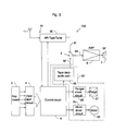
- Audio unit 100 has an amplifier 6 which amplifies either a first audio signal from a radio unit 90, or a second audio signal from a tape deck 20.
- a position of a source selection switch 5 determines which of the two audio signals is amplified and output to a speaker 7.
- Source selection switch 5 is controlled by a control circuit 9.
- Radio unit 90 includes a radio tuner 10 and a reception antenna 11.
- Radio tuner 10 receives broadcast signals from amplitude modulation (AM) or frequency modulation (FM) transmissions.
- Radio tuner 10 outputs an audio signal through a radio output line 61 to one input of source selector switch 5.
- Tape deck 20 includes a tape deck audio path 25 which generates an audio signal through a tape output line 62 when tape deck 20 plays a tape (not shown).
- Tape output line 62 is connected to a second input of source selection switch 5.
- An input device such as, for example, a keyboard 3, allows a user to select an operating mode for audio unit 100.
- An input latch circuit 4 stores a selected operating mode in its memory (not shown).
- An ISR switch 8 sends an ISR control signal to control circuit 9.
- the control signal from ISR switch 8 causes radio tuner 10 to adjust to a pre-set frequency.
- the pre-set frequency could be 1620 kHz, the frequency of a traffic information broadcast station in certain areas.
- Control circuit 9 contains a random access memory circuit (RAM, not shown) that memorizes the operating mode that is current when ISR switch 8 is activated.
- Tape deck 20 has a plunger driver circuit 22, controlled by an output signal from control circuit 9, which actuates a plunger 21.
- Plunger 21 moves a head and pinch roller (not shown) into contact with a magnetic tape (not shown).
- a motor driver circuit 24, controlled by an output signal from control circuit 9, drives and controls motor 23. Motor 23 feeds the magnetic tape.
- Audio unit 100 has several operating modes including a radio reception mode and several tape modes.
- a radio reception mode is a normal playback mode and several special playback modes, including fast forward mode (FF-APC), rewind mode (REW-APC) and pause mode.
- FF-APC fast forward mode
- REW-APC rewind mode
- keyboard 3 is used to select a desired reception frequency which is sent to input latch circuit4.
- Input latch circuit 4 sends an operating mode signal to control circuit 9.
- Control circuit 9 sends a reception control signal to radio tuner 10, setting radio tuner 10 to the desired frequency. This causes radio tuner 10 to output an audio signal of a broadcast at the selected frequency to radio output line 61.
- Control.circuit 9 sends a selection control signal to a source selection switch 5 causing it to connect radio output line 61 to amplifier 6.
- the audio signal from radio tuner 10 is then output through radio output line 61 and source selection switch 5 to amplifier 6.
- Amplifier 6 amplifies the signal, which is sent to speaker 7.
- Control circuit 9 sends a selection control signal to source selection switch 5 to switch the audio source to tape output line 62.
- Control circuit 9 also sends appropriate control signals to plunger driver circuit 22, motor driver circuit 24 and tape deck audio path 25. These control signals cause plunger driver circuit 22 and motor driver circuit 24 to actuate plunger 21 and motor 23 perform the commanded function such as playing the tape. Playing the tape causes tape deck audio path 25 to generate an audio signal.
- the audio signal from tape deck 20 is then output through tape output line 62 to source selection switch 5 to an amplifier input 64 of amplifier 6.
- Amplifier 6 amplifies the signal and sends an amplified output to speaker 7.
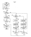
- Step S12 branches to step S13 if ISR switch 8 is on and loops back to S11 if ISR switch 8 is off.
- Step S13 branches to step S14 if the current operating mode is the radio reception mode. If the current operating is mode is not the radio reception mode, step S13 branches to step S17.
- a reception control signal is sent to receive the traffic information broadcast.
- Control then proceeds to step S15.
- Step S15 loops back to itself until ISR switch 8 is activated again.
- control proceeds to step S16 where the operating mode, stored in RAM at Step S11, is activated.
- Step S17 branches to step S18 if the current operating mode is the normal tape playback mode.
- step S18 a control signal is sent to put tape deck 20 in a playback pause mode which stops the tape then playing.
- step S19 where a reception control signal is sent to receive the traffic information broadcast.
- step S20 where a selection control signal is sent to source selection switch 5.
- the selection control signal causes source selection switch 5 to connect radio output line 61 to amplifier input 64 causing the radio output to be amplified and output to speaker 7.
- Control proceeds to step S21.
- Step S21 branches to step S16 if ISR switch 8 is reactivated or loops back to itself if ISR switch 8 is off.
- step S17 If the current operating mode at step S17 is not the normal tape playback mode, then control branches to step S22. For example, if the current operating mode is a special playback mode such as FF-APC or REW-APC, then control branches to step S22. At step S22, the current special playback mode is continued. Control then proceeds to step S23. At step S23, a reception control signal is sent to receive the traffic information broadcast. Control then proceeds to step S24, where a selection control signal is sent to source selection switch 5 to connect amplifier input 64 to radio output line 61. Control then proceeds to step S25 which branches to step S16 if ISR switch is on, or to step S17 if if ISR switch 8 is off.
- FF-APC FF-APC or REW-APC
- step S17 if the current mode at step S17 is not the normal tape playback mode, then the current special playback mode is continued.
- the special playback mode is FF-APC or REW-APC
- tape deck 20 continues to fast-forward or rewind the tape as control proceeds to step S23.
- step S23 a reception control signal is sent to receive the traffic information broadcast.
- step S24 a selection control signal is sent to source selection switch 5 to connect radio output line 61 to amplifier input 64 causing the radio output to be amplified and output to speaker 7. Since the special function is continued rather than paused at step S22, the tape continues the special function while audio unit 100 outputs the traffic information broadcast.
- step S25 branches to step S16 if ISR switch 8 is on again. If ISR switch 8 is still off, control proceeds to step S17.
- step S17 the current operating mode is checked again. If the special playback mode has completed, the operating mode will have switched to normal tape playback mode. For example, if tape deck 20 has finished rewinding the tape, the normal playback mode is automatically invoked. If the normal playback mode is the current operating mode, step S17 branches to step S18 where tape deck 20 is put in pause mode. The traffic information broadcastcon- tinues to be output. Control proceeds through steps S19 and S20. These steps do not affect the operating mode of audio unit 100 since it is already outputting the traffic information broadcast. When operation reaches step S21, control loops until ISR switch 8 is reactivated.
- ISR switch 8 If ISR switch 8 is activated when tape deck 20 is in a special playback mode, the traffic information broadcast is outputted and the function of the special playback mode continues. If the function of the special playback mode is completed before the traffic information broadcast is finished, the current operating mode switches to normal playback mode.
- the switch to normal playback mode is performed internally by tape deck 20 by a process external to the control flow of Fig. 2.
- the switch to normal playback is detected in step S17.
- Tape deck 20 is put in pause mode in step S18 and the traffic information broadcast continued in steps S19 and S20. Control loops at step S21 until ISRswitch 8 is reactivated, indicating the user wishes to switch back to tape deck 20. Since the special playback mode was continued during the traffic information broadcast, the tape will begin playing at the point where it would have been upon completion of the special playback function.
- FIG. 3 a block diagram of a second embodiment of the invention, audio unit 150, is shown in Fig. 3.
- the only difference between Figs. 1 and 3 is that the function of ISR switch 8 is replaced by an internal function of a special radio tuner, called anARI-type tuner 30, described below.
- Elements that are identical to the first embodiment are given the same notation and the explanation of their composition and operation are as described with reference to Fig. 1.
- radio tuner 10 of Fig. 1 is replaced by ARI-type tuner 30.
- ARI-type tuner 30 is a radio tuner equipped to receive identification signals, called DK signals. DK signals indicate the presence of a special type of traffic information broadcast, or ARI broadcasts, which are made at a specified frequency set internally in ARI-type tuner 30.
- DK signals indicate the presence of a special type of traffic information broadcast, or ARI broadcasts, which are made at a specified frequency set internally in ARI-type tuner 30.
- a control signal is sent to control circuit 9 to indicate the event. This function replaces ISR switch 8 of the first embodiment of Fig. 1.
- control circuit 9 operation of control circuit 9 according to the second embodiment is as follows.
- the operation sequence is identical to that described with reference to Fig. 2, except that the radio reception mode is invoked in response to a DK signal from ARI-type tuner 30 instead of an ISR signal from ISR switch 8. Both the signal from ISR switch 8 and the DK signal are sent to control circuit 9 in the respective embodiments.
- Fig. 4 is a flow-chart which shows the operation of the control circuit from the time a DK signal from an ARI broadcast is received.
- the operation of the second embodiment is identical to that of the first except for the replacement of the ISR signal with the DK signal.
- the traffic information broadcast is outputted and the function of the special playback mode is continued until completed. If the function of the special playback mode is completed before the traffic information broadcast is finished, the current operating mode switches to normal playback mode. The switch to normal playback mode is detected in step S37. Then tape deck 20 is put in pause mode in step 538 and the traffic information broadcast continued in steps S39 and S40. Then control loops at step S41 until a new DK signal is received.
- the tape begins to play at the point where it would have been after completion of the special playback function.
- a third embodiment of the invention includes an audio unit 160 that is identical to that of audio unit 150 of Fig. 3, except that ARI-type tuner 30 is replaced by an RDS-type tuner 40 equipped to receive identification signals, called TAsignals from RDS broadcast stations.
- TA signals indicate the presence of a type of traffic information broadcast, or RDS broadcasts, which are made at a specified frequency set internally in the RDS-type tuner 40.
- a control signal is sent to control circuit 9 to indicate the event. This function replaces ISR switch 8 of audio unit 100 of Fig. 1.
- control circuit 9 operation of control circuit 9 according to the third embodiment of the invention is identical to that of the first embodiment of Fig. 2, except that the radio reception mode is invoked in response to a TA signal from an RDS-type tuner 40 instead of a signal from ISR switch 8 of Fig. 1.
- Fig. 6 is a flow-chart which shows the operation of the control circuit from the time a TA signal from an RDS broadcast is received.
- the flow-chart of Fig. 6 is identical to that of Fig. 2 except that the TA signal plays the role of the ISR signal from ISR switch 8.
- the traffic information broadcast is outputted and the function of the special playback mode continues. If the function of the special playback mode is completed before the traffic information broadcast is finished, the current operating mode switches to normal playback mode. The switch to normal playback mode is detected in step S57. Then tape deck 20 is put in pause mode in step S58 and the traffic information broadcast continued in steps S59 and S60. Then control loops at step S61 until a new TA signal is received. Thus, when a new TA signal is received indicating the traffic information broadcast is over, the tape will play at the point where it would have been after completion of the special playback function.
- FF-APC and REW-APC were given as examples of special playback modes. It is noted that the FF and REW modes could also be substituted for these in keeping with the spirit of the invention.
- the recording playback device was a tape deck 20. It is noted that any other player of a recorded medium could be substituted for tape deck 20 of the above embodiments.
- a CD-player could be used.
- the function occurring may be, for example, a track change, which the present invention would permit continuance of until completed.
- the function may be, for example, a disc change, which the present invention would permit continuance of until completed.
Landscapes
- Engineering & Computer Science (AREA)
- Signal Processing (AREA)
- Multimedia (AREA)
- Computer Networks & Wireless Communication (AREA)
- Physics & Mathematics (AREA)
- General Physics & Mathematics (AREA)
- Input Circuits Of Receivers And Coupling Of Receivers And Audio Equipment (AREA)
- Circuits Of Receivers In General (AREA)
Applications Claiming Priority (3)
| Application Number | Priority Date | Filing Date | Title |
|---|---|---|---|
| JP29826292A JP3298674B2 (ja) | 1992-10-12 | 1992-10-12 | オーディオ装置 |
| JP298262/92 | 1992-10-12 | ||
| JP29826292 | 1992-10-12 |
Publications (3)
| Publication Number | Publication Date |
|---|---|
| EP0593024A2 true EP0593024A2 (fr) | 1994-04-20 |
| EP0593024A3 EP0593024A3 (fr) | 1994-08-03 |
| EP0593024B1 EP0593024B1 (fr) | 2003-07-30 |
Family
ID=17857355
Family Applications (1)
| Application Number | Title | Priority Date | Filing Date |
|---|---|---|---|
| EP93116513A Expired - Lifetime EP0593024B1 (fr) | 1992-10-12 | 1993-10-12 | Dispositif électronique |
Country Status (4)
| Country | Link |
|---|---|
| US (1) | US5483506A (fr) |
| EP (1) | EP0593024B1 (fr) |
| JP (1) | JP3298674B2 (fr) |
| DE (1) | DE69333123T2 (fr) |
Cited By (6)
| Publication number | Priority date | Publication date | Assignee | Title |
|---|---|---|---|---|
| EP0865175A2 (fr) * | 1997-01-24 | 1998-09-16 | Kabushiki Kaisha Kenwood | Récepteur de programmes radiophoniques, qui est capable de capter plusieurs systèmes de transmission, comme par example la radiodiffusion numérique (DAB) et la transmission de données supplémentaires (RDS) |
| EP1227478A2 (fr) * | 2001-01-25 | 2002-07-31 | Pioneer Corporation | Dispositif de commutation et appareil d'enregistrement/reproduction muni de ce dispositif de commutation |
| WO2002085021A2 (fr) * | 2001-04-18 | 2002-10-24 | Robert Bosch Gmbh | Procede de lecture de donnees multimedia au moyen d'un appareil de divertissement |
| EP1571671A1 (fr) * | 2002-12-13 | 2005-09-07 | Matsushita Electric Industrial Co., Ltd. | Dispositif a disque optique |
| WO2008026187A2 (fr) * | 2006-08-31 | 2008-03-06 | Grundig Elektronik Anonim Sirketi | Procédé de visualisation d'un contenu du moment alors que la personne regarde des programmes enregistrés |
| CN107886976A (zh) * | 2017-12-26 | 2018-04-06 | 深圳市佳音王科技股份有限公司 | 一种多功能组合电唱机及其装置 |
Families Citing this family (21)
| Publication number | Priority date | Publication date | Assignee | Title |
|---|---|---|---|---|
| US5920842A (en) * | 1994-10-12 | 1999-07-06 | Pixel Instruments | Signal synchronization |
| US5758257A (en) * | 1994-11-29 | 1998-05-26 | Herz; Frederick | System and method for scheduling broadcast of and access to video programs and other data using customer profiles |
| US5815471A (en) * | 1996-03-19 | 1998-09-29 | Pics Previews Inc. | Method and apparatus for previewing audio selections |
| US5671195A (en) * | 1996-05-31 | 1997-09-23 | Intellectual Science And Technology Inc. | Audio system programmable for recording preselected audio broadcasts |
| US5790481A (en) * | 1996-11-21 | 1998-08-04 | Meitner; Edmund | Retrofitable CD player system |
| US5761159A (en) * | 1996-12-24 | 1998-06-02 | Ashenafi; Solomon M. | Automatic radio program recorder |
| US6072753A (en) * | 1996-12-24 | 2000-06-06 | Ashenafi; Solomon M. | Automatic radio program recorder |
| US6553404B2 (en) | 1997-08-08 | 2003-04-22 | Prn Corporation | Digital system |
| WO1999008216A1 (fr) | 1997-08-08 | 1999-02-18 | Pics Previews, Inc. | Procede et appareil permettant de distribuer un contenu audiovisuel |
| US6240280B1 (en) * | 1997-08-26 | 2001-05-29 | Thomson Consumer Electronics Sales Gmbh | Selection of traffic capable station by RDS radio while listening to other media |
| KR100300590B1 (ko) * | 1998-07-15 | 2001-10-27 | 구자홍 | 오디오의동작모드에따른기능절환방법 |
| US6600908B1 (en) | 1999-02-04 | 2003-07-29 | Hark C. Chan | Method and system for broadcasting and receiving audio information and associated audio indexes |
| US7369824B1 (en) | 1999-02-04 | 2008-05-06 | Chan Hark C | Receiver storage system for audio program |
| US7245707B1 (en) | 1999-03-26 | 2007-07-17 | Chan Hark C | Data network based telephone messaging system |
| US20040260415A1 (en) * | 1999-09-08 | 2004-12-23 | Weiss Kenneth P. | Method and apparatus for achieving selected audio and other functions |
| US20090322953A1 (en) * | 1999-09-08 | 2009-12-31 | Weiss Kenneth P | Method and apparatus for achieving selected audio/video and other functions |
| DE10011260A1 (de) * | 2000-03-08 | 2001-09-20 | Bosch Gmbh Robert | Verfahren zur Aufzeichnung über eine Rundfunkfrequenz übertragener Information |
| JP2003078279A (ja) * | 2001-09-04 | 2003-03-14 | Konica Corp | プリント基板のシールド方法及びその方法を用いたプリント基板が装着された装置 |
| JP2004022139A (ja) * | 2002-06-19 | 2004-01-22 | Pioneer Electronic Corp | 電子機器セット、第1及び第2電子機器、並びにコンピュータプログラム |
| CN100386816C (zh) * | 2002-08-22 | 2008-05-07 | 乐金电子(惠州)有限公司 | 拆卸式音频播放机的功能模式设置装置及方法 |
| US20040212478A1 (en) * | 2003-04-25 | 2004-10-28 | John Kutsuzawa | Remote control activator with voice data memory and associated method |
Citations (1)
| Publication number | Priority date | Publication date | Assignee | Title |
|---|---|---|---|---|
| DE4031431A1 (de) * | 1989-12-06 | 1991-06-13 | Pioneer Electronic Corp | Verkehrsinformationsempfaenger |
Family Cites Families (4)
| Publication number | Priority date | Publication date | Assignee | Title |
|---|---|---|---|---|
| DE3534064A1 (de) * | 1984-09-26 | 1986-04-03 | Mitsubishi Denki K.K., Tokio/Tokyo | Empfangsgeraet |
| JPS62107490A (ja) * | 1985-11-01 | 1987-05-18 | Fujitsu Ten Ltd | ラジオ受信機を備える音響機器 |
| JPH0426983A (ja) * | 1990-05-21 | 1992-01-30 | Matsushita Electric Ind Co Ltd | カセット蓋開閉装置 |
| US5263199A (en) * | 1991-03-13 | 1993-11-16 | Ronald P. Barnes | Vehicle accessory having integrally contained radio receiver and recording means |
-
1992
- 1992-10-12 JP JP29826292A patent/JP3298674B2/ja not_active Expired - Fee Related
-
1993
- 1993-10-12 DE DE69333123T patent/DE69333123T2/de not_active Expired - Lifetime
- 1993-10-12 EP EP93116513A patent/EP0593024B1/fr not_active Expired - Lifetime
- 1993-10-12 US US08/135,239 patent/US5483506A/en not_active Expired - Lifetime
Patent Citations (1)
| Publication number | Priority date | Publication date | Assignee | Title |
|---|---|---|---|---|
| DE4031431A1 (de) * | 1989-12-06 | 1991-06-13 | Pioneer Electronic Corp | Verkehrsinformationsempfaenger |
Cited By (14)
| Publication number | Priority date | Publication date | Assignee | Title |
|---|---|---|---|---|
| EP0865175A3 (fr) * | 1997-01-24 | 2000-05-10 | Kabushiki Kaisha Kenwood | Récepteur de programmes radiophoniques, qui est capable de capter plusieurs systèmes de transmission, comme par example la radiodiffusion numérique (DAB) et la transmission de données supplémentaires (RDS) |
| EP0865175A2 (fr) * | 1997-01-24 | 1998-09-16 | Kabushiki Kaisha Kenwood | Récepteur de programmes radiophoniques, qui est capable de capter plusieurs systèmes de transmission, comme par example la radiodiffusion numérique (DAB) et la transmission de données supplémentaires (RDS) |
| EP1227478A3 (fr) * | 2001-01-25 | 2003-09-17 | Pioneer Corporation | Dispositif de commutation et appareil d'enregistrement/reproduction muni de ce dispositif de commutation |
| EP1227478A2 (fr) * | 2001-01-25 | 2002-07-31 | Pioneer Corporation | Dispositif de commutation et appareil d'enregistrement/reproduction muni de ce dispositif de commutation |
| US6845413B2 (en) | 2001-01-25 | 2005-01-18 | Pioneer Corporation | Switchover device and information recording/reproducing apparatus having the switchover device |
| WO2002085021A2 (fr) * | 2001-04-18 | 2002-10-24 | Robert Bosch Gmbh | Procede de lecture de donnees multimedia au moyen d'un appareil de divertissement |
| WO2002085021A3 (fr) * | 2001-04-18 | 2003-05-08 | Bosch Gmbh Robert | Procede de lecture de donnees multimedia au moyen d'un appareil de divertissement |
| US7499630B2 (en) | 2001-04-18 | 2009-03-03 | Robert Bosch Gmbh | Method for playing back multimedia data using an entertainment device |
| EP1571671A1 (fr) * | 2002-12-13 | 2005-09-07 | Matsushita Electric Industrial Co., Ltd. | Dispositif a disque optique |
| EP1571671A4 (fr) * | 2002-12-13 | 2008-04-02 | Matsushita Electric Ind Co Ltd | Dispositif a disque optique |
| WO2008026187A2 (fr) * | 2006-08-31 | 2008-03-06 | Grundig Elektronik Anonim Sirketi | Procédé de visualisation d'un contenu du moment alors que la personne regarde des programmes enregistrés |
| WO2008026187A3 (fr) * | 2006-08-31 | 2008-06-19 | Beko Elektronik Anonim Sirketi | Procédé de visualisation d'un contenu du moment alors que la personne regarde des programmes enregistrés |
| CN107886976A (zh) * | 2017-12-26 | 2018-04-06 | 深圳市佳音王科技股份有限公司 | 一种多功能组合电唱机及其装置 |
| CN107886976B (zh) * | 2017-12-26 | 2024-02-09 | 深圳市佳音王科技股份有限公司 | 一种多功能组合电唱机及其装置 |
Also Published As
| Publication number | Publication date |
|---|---|
| DE69333123T2 (de) | 2004-04-15 |
| DE69333123D1 (de) | 2003-09-04 |
| JP3298674B2 (ja) | 2002-07-02 |
| EP0593024A3 (fr) | 1994-08-03 |
| US5483506A (en) | 1996-01-09 |
| EP0593024B1 (fr) | 2003-07-30 |
| JPH06124580A (ja) | 1994-05-06 |
Similar Documents
| Publication | Publication Date | Title |
|---|---|---|
| US5483506A (en) | Radio receiver with playback means | |
| EP0644662B1 (fr) | Récepteur radio avec une fonction d'enregistrement et reproduction | |
| US6845413B2 (en) | Switchover device and information recording/reproducing apparatus having the switchover device | |
| JPS6220428A (ja) | カ−ステレオ装置 | |
| JP3131970B2 (ja) | ステレオ再生装置 | |
| JPS62107490A (ja) | ラジオ受信機を備える音響機器 | |
| JPH055704Y2 (fr) | ||
| KR100213768B1 (ko) | 방송 주파수 수신 기능을 갖는 콤팩트 디스크 플레이어의 교환 청취방법 | |
| JPH0135359Y2 (fr) | ||
| JPH02203466A (ja) | 記録媒体演秦装置のミュート解除方法 | |
| JPS606953Y2 (ja) | ラジオ受信機付テ−プレコ−ダーの制御装置 | |
| JPH01208031A (ja) | ラジオ受信機 | |
| JPH087598Y2 (ja) | 車載用音響機器 | |
| KR100281167B1 (ko) | 오디오신호의 재생시간 제어 방법 | |
| JPS6327481Y2 (fr) | ||
| KR950001229Y1 (ko) | Rds신호수신장치 | |
| JP3461035B2 (ja) | 車載用音響装置 | |
| JP3189596B2 (ja) | 車載用音響装置 | |
| JPH05198149A (ja) | 車載用交通情報受信装置 | |
| JPH09161466A (ja) | 目覚まし機能付記録再生装置 | |
| JPH11339451A (ja) | 入力源出力制御装置 | |
| JPH10256925A (ja) | ラジオ受信機能付き音響機器 | |
| JPH1040605A (ja) | 記録再生装置 | |
| KR20000033659A (ko) | 카 오디오의 카세트 구동 제어방법 | |
| JPH064991U (ja) | 音響機器のファンクション切換装置 |
Legal Events
| Date | Code | Title | Description |
|---|---|---|---|
| PUAI | Public reference made under article 153(3) epc to a published international application that has entered the european phase |
Free format text: ORIGINAL CODE: 0009012 |
|
| AK | Designated contracting states |
Kind code of ref document: A2 Designated state(s): DE FR GB |
|
| PUAL | Search report despatched |
Free format text: ORIGINAL CODE: 0009013 |
|
| AK | Designated contracting states |
Kind code of ref document: A3 Designated state(s): DE FR GB |
|
| 17P | Request for examination filed |
Effective date: 19940730 |
|
| 17Q | First examination report despatched |
Effective date: 19960924 |
|
| GRAG | Despatch of communication of intention to grant |
Free format text: ORIGINAL CODE: EPIDOS AGRA |
|
| GRAG | Despatch of communication of intention to grant |
Free format text: ORIGINAL CODE: EPIDOS AGRA |
|
| GRAH | Despatch of communication of intention to grant a patent |
Free format text: ORIGINAL CODE: EPIDOS IGRA |
|
| GRAG | Despatch of communication of intention to grant |
Free format text: ORIGINAL CODE: EPIDOS AGRA |
|
| GRAH | Despatch of communication of intention to grant a patent |
Free format text: ORIGINAL CODE: EPIDOS IGRA |
|
| GRAH | Despatch of communication of intention to grant a patent |
Free format text: ORIGINAL CODE: EPIDOS IGRA |
|
| GRAH | Despatch of communication of intention to grant a patent |
Free format text: ORIGINAL CODE: EPIDOS IGRA |
|
| GRAA | (expected) grant |
Free format text: ORIGINAL CODE: 0009210 |
|
| AK | Designated contracting states |
Designated state(s): DE FR GB |
|
| REG | Reference to a national code |
Ref country code: GB Ref legal event code: FG4D |
|
| REF | Corresponds to: |
Ref document number: 69333123 Country of ref document: DE Date of ref document: 20030904 Kind code of ref document: P |
|
| ET | Fr: translation filed | ||
| PLBE | No opposition filed within time limit |
Free format text: ORIGINAL CODE: 0009261 |
|
| STAA | Information on the status of an ep patent application or granted ep patent |
Free format text: STATUS: NO OPPOSITION FILED WITHIN TIME LIMIT |
|
| 26N | No opposition filed |
Effective date: 20040504 |
|
| PGFP | Annual fee paid to national office [announced via postgrant information from national office to epo] |
Ref country code: DE Payment date: 20121010 Year of fee payment: 20 Ref country code: FR Payment date: 20121018 Year of fee payment: 20 |
|
| PGFP | Annual fee paid to national office [announced via postgrant information from national office to epo] |
Ref country code: GB Payment date: 20121010 Year of fee payment: 20 |
|
| REG | Reference to a national code |
Ref country code: DE Ref legal event code: R071 Ref document number: 69333123 Country of ref document: DE |
|
| REG | Reference to a national code |
Ref country code: GB Ref legal event code: PE20 Expiry date: 20131011 |
|
| PG25 | Lapsed in a contracting state [announced via postgrant information from national office to epo] |
Ref country code: DE Free format text: LAPSE BECAUSE OF EXPIRATION OF PROTECTION Effective date: 20131015 Ref country code: GB Free format text: LAPSE BECAUSE OF EXPIRATION OF PROTECTION Effective date: 20131011 |