EP0586958B1 - Einrichtung zum Vorfiltern des Feuchtwassers - Google Patents
Einrichtung zum Vorfiltern des Feuchtwassers Download PDFInfo
- Publication number
- EP0586958B1 EP0586958B1 EP93113461A EP93113461A EP0586958B1 EP 0586958 B1 EP0586958 B1 EP 0586958B1 EP 93113461 A EP93113461 A EP 93113461A EP 93113461 A EP93113461 A EP 93113461A EP 0586958 B1 EP0586958 B1 EP 0586958B1
- Authority
- EP
- European Patent Office
- Prior art keywords
- printing unit
- prefilter
- door
- unit according
- damping
- Prior art date
- Legal status (The legal status is an assumption and is not a legal conclusion. Google has not performed a legal analysis and makes no representation as to the accuracy of the status listed.)
- Expired - Lifetime
Links
Images
Classifications
-
- B—PERFORMING OPERATIONS; TRANSPORTING
- B41—PRINTING; LINING MACHINES; TYPEWRITERS; STAMPS
- B41F—PRINTING MACHINES OR PRESSES
- B41F7/00—Rotary lithographic machines
- B41F7/20—Details
- B41F7/24—Damping devices
- B41F7/32—Ducts, containers, or like supply devices for liquids
-
- B—PERFORMING OPERATIONS; TRANSPORTING
- B41—PRINTING; LINING MACHINES; TYPEWRITERS; STAMPS
- B41F—PRINTING MACHINES OR PRESSES
- B41F7/00—Rotary lithographic machines
- B41F7/20—Details
- B41F7/24—Damping devices
-
- B—PERFORMING OPERATIONS; TRANSPORTING
- B41—PRINTING; LINING MACHINES; TYPEWRITERS; STAMPS
- B41P—INDEXING SCHEME RELATING TO PRINTING, LINING MACHINES, TYPEWRITERS, AND TO STAMPS
- B41P2235/00—Cleaning
- B41P2235/30—Recovering used solvents or residues
- B41P2235/31—Recovering used solvents or residues by filtering
Definitions
- the invention relates to a device for prefiltering the fountain solution in a printing press with at least one printing unit.
- a pre-filter device is provided, which is assigned to each printing unit of a printing press.
- This pre-filter device is arranged in a separate housing, which is usually arranged outside the printing press.
- Such separate apparatuses not only leave a negative impression visually, but also hinder working on the printing press.
- the invention is based on the object of proposing a device which avoids these disadvantages of the prior art.
- a further development of the device according to the invention provides that at least part of a housing wall of the prefilter housing is designed as a door. It is particularly advantageous that this door is also the door on the operating side of the printing unit. This construction ensures that the prefilter is easily accessible from the operator side, for example. It is easy to change the filter mats.
- the frame of the prefilter housing be provided with elastic sealing material is provided.
- this sealing material is foam.
- a collecting container for the dampening water is located under the filter housing in which the pre-filter is arranged. This collecting container is dimensioned so that the dampening water collects here when the printing machine is switched off.
- a further development of the device according to the invention provides channels in which the hoses for returning the dampening water run from a dampening unit to the prefilter housing.
- the hoses do not hinder any further elements of the printing unit.
- the channels are designed in such a way that there are no short bends or kinks in the hose guide. Since deposits are preferred at kinks, the smooth hose routing largely prevents contamination - and in extreme cases clogging of the hoses.
- the top of the prefilter housing is designed as a trough. This pan is used to collect oil.
- This combination of drip pan and prefilter housing is particularly simple and inexpensive.
- a line leads the fountain solution from the pre-filters in the printing units to a main filter.
- a main filter has become known, for example, from utility model DE-U1 91 01 888.
- a device for displaying the dampening solution level is arranged in the prefilter.
- the dampening solution level is checked using a float switch.
- An increase in the dampening solution level is usually an indication that the filter has become clogged due to impurities and that there is a dampening solution accumulation in the area of the pre-filter. Since overflowing dampening solution can also be briefly cleaned by the main filter, it is sufficient for the float switch to activate a warning indicator. Since the main filter can temporarily take over the task of the pre-filter, the filter mats can be replaced while the printing machine is in operation.
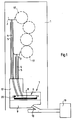
- Fig. 1 is a section through a printing unit 1 of a web-fed rotary printing press, not shown separately shown.
- this printing unit 1 the device according to the invention for pre-filtering the fountain solution is integrated.
- An upper dampening unit 2 and a lower dampening unit 3 are assigned to the pressure cylinders 17.
- the return of the dampening water from the dampening units 2, 3 takes place via hoses 4, which are guided in channels 5.
- the dampening water to be cleaned passes through the hoses 4 into a pre-filter 6 in which filter mats 8 are arranged.
- the pre-filter 6 is arranged in the filter housing 7. This filter housing is closed by a door 12 on the operating side of the printing unit 1.
- a collecting container 9 which is at least dimensioned such that it can hold the dampening water flowing out of the dampening units 2, 3 and the pre-filter 6 when the machine stops.
- the collecting container 9 is connected to the main filter 19 via a collecting line 10.
- a level indicator 20 for example a float switch, is arranged in the pre-filter 6 and activates a warning display when a certain level is exceeded.
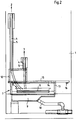
- Fig. 2 shows a longitudinal section through the device according to the invention for pre-filtering the fountain solution.
- the device according to the invention is arranged in the lower region of the printing unit 1.
- the dampening water is fed from the upper and lower dampening units 2, 3 into the prefilter 6 via hoses 4. These hoses 4 are guided in channels 5.
- the prefilter 6, in which the filter mats 8 are arranged, is located in the filter housing 7. Below the prefilter 6, there is the collecting container 9. From this collecting container 9, the dampening solution is transferred via a Line 10 passed to the main filter 19, not shown.
- the prefilter housing 7 is closed by a door 12.
- This door 12 is also the door on the operating side of the printing unit 1.
- the frame of the pre-filter housing 7, which serves to accommodate the door 12, is provided with elastic sealing material 13.
- This elastic sealing material 13 is, for example, foam.
- webs are additionally provided on the frame of the door, which are pressed into the sealing material when the door is closed. This results in an effective sealing of the areas that carry the dampening solution.
- the top 15 of the prefilter housing 7 is advantageously designed as a trough 18.
- the top 15 of the prefilter housing 7 is at the same time suitable for collecting oil from central lubrication escaping from bearings. Since the upper side 15 of the prefilter housing 7 thus fulfills a double function, this design is particularly cost-effective.
- the oil is discharged from the trough 17 via an outlet connection 16.
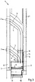
- Fig. 3 shows a cross section through the device according to the invention for prefiltering the fountain solution.
- the prefilter 6 is arranged in the upper region of the filter housing 7;
- the collecting container 9 is located in the lower area. Sealing material 13 and webs 14 engaging in this sealing material, which are located on the inside of the door 12, isolate the areas that carry the dampening solution.
- dampening agent-carrying hoses 4 are guided through the side wall 11 of the printing unit 1 and then through channels 5, so that they do not impede any control elements of the printing unit 1.
Landscapes
- Engineering & Computer Science (AREA)
- Mechanical Engineering (AREA)
- Rotary Presses (AREA)
- Filtering Materials (AREA)
- Water Treatment By Sorption (AREA)
Applications Claiming Priority (2)
| Application Number | Priority Date | Filing Date | Title |
|---|---|---|---|
| DE4229311A DE4229311C1 (de) | 1992-09-02 | 1992-09-02 | Vorrichtung zum Reinigen des Feuchtwassers |
| DE4229311 | 1992-09-02 |
Publications (3)
| Publication Number | Publication Date |
|---|---|
| EP0586958A2 EP0586958A2 (de) | 1994-03-16 |
| EP0586958A3 EP0586958A3 (OSRAM) | 1994-08-03 |
| EP0586958B1 true EP0586958B1 (de) | 1996-10-23 |
Family
ID=6467062
Family Applications (1)
| Application Number | Title | Priority Date | Filing Date |
|---|---|---|---|
| EP93113461A Expired - Lifetime EP0586958B1 (de) | 1992-09-02 | 1993-08-24 | Einrichtung zum Vorfiltern des Feuchtwassers |
Country Status (5)
| Country | Link |
|---|---|
| US (1) | US5415091A (OSRAM) |
| EP (1) | EP0586958B1 (OSRAM) |
| JP (1) | JP2956816B2 (OSRAM) |
| AT (1) | ATE144461T1 (OSRAM) |
| DE (2) | DE4229311C1 (OSRAM) |
Families Citing this family (12)
| Publication number | Priority date | Publication date | Assignee | Title |
|---|---|---|---|---|
| DE9413438U1 (de) | 1994-08-19 | 1995-06-22 | Baldwin-Gegenheimer Gmbh, 86165 Augsburg | Druckmaschinen-Temperierungssystem |
| US5839364A (en) * | 1994-09-19 | 1998-11-24 | Goss Graphic Systems, Inc. | Dampening system for a printing press |
| DE19949906A1 (de) * | 1999-10-16 | 2001-04-19 | Baldwin Grafotec Gmbh | Druckmaschinen-Reinigungsvorrichtung |
| US6293198B1 (en) * | 2000-10-13 | 2001-09-25 | S. T. Engineering Co., Ltd. | Circulation treatment system and method for treating fountain solution |
| DE10163341C2 (de) * | 2001-12-21 | 2003-12-11 | Ludwig E Betz Gmbh Druckmaschi | Vorrichtung und Verfahren zum Reinigen von verschmutztem Reinigungsmittel von Druckmaschinen |
| DE10213959A1 (de) * | 2002-03-28 | 2003-10-09 | Baldwin Germany Gmbh | Feuchtwasserkreislaufabschnitt |
| US6908558B2 (en) * | 2003-03-19 | 2005-06-21 | David J. Stinson | Fountain solution recycling system for commercial printers |
| DE102004021508B4 (de) * | 2004-04-30 | 2007-04-19 | Technotrans Ag | Verfahren und Vorrichtung zur Reinigung des Feuchtmittels einer Druckmaschine |
| ITMI20041698A1 (it) * | 2004-09-03 | 2004-12-03 | Ecografica S R L | Apparecchiatura e procedimento per ottimizare le caratteristiche dell'acqua di bagnatura nelle macchine per stampa offset |
| JP4908353B2 (ja) * | 2007-09-04 | 2012-04-04 | 篤 新西 | 湿し水循環装置 |
| US20150059059A1 (en) * | 2013-09-04 | 2015-03-05 | Gregg Teskey | Mid length dress sock |
| CN104890350A (zh) * | 2015-06-30 | 2015-09-09 | 云南华红印刷有限公司 | 胶印机水箱 |
Family Cites Families (8)
| Publication number | Priority date | Publication date | Assignee | Title |
|---|---|---|---|---|
| DE905741C (de) * | 1948-04-03 | 1954-03-04 | Dick Co Ab | Befeuchten der Druckform von Rotationsflachdruckmaschinen |
| US3288061A (en) * | 1963-12-31 | 1966-11-29 | Miehle Goss Dexter Inc | Press inking arrangement |
| US3949668A (en) * | 1974-10-17 | 1976-04-13 | Smith R.P.M. Corporation | Liquid feed for offset press dampening system |
| DE2745741B2 (de) * | 1976-10-15 | 1981-04-16 | Nikkei Shoji Co., Ltd., Tokyo | Verfahren und Vorrichtung zur Regulierung des in nach dem lithographischen Verfahren arbeitenden Druckmaschinen verwendeten Feuchtwassers |
| US4574695A (en) * | 1984-09-24 | 1986-03-11 | Mirachem Corporation Ltee/Ltd. | Press dampening roll fountain |
| US5109770A (en) * | 1989-09-22 | 1992-05-05 | Oxy-Dry Corporation | Printing cylinder cleaning system |
| JP2504596Y2 (ja) * | 1990-01-26 | 1996-07-10 | 富士写真フイルム株式会社 | 湿し水自動補充装置 |
| DE9101888U1 (de) * | 1990-07-04 | 1991-05-08 | Technotrans Böhnensieker GmbH, 4414 Sassenberg | Vorrichtung zur Bereitstellung von Prozesswasser für Druckmaschinen |
-
1992
- 1992-09-02 DE DE4229311A patent/DE4229311C1/de not_active Expired - Fee Related
-
1993
- 1993-08-24 DE DE59304273T patent/DE59304273D1/de not_active Expired - Fee Related
- 1993-08-24 AT AT93113461T patent/ATE144461T1/de not_active IP Right Cessation
- 1993-08-24 EP EP93113461A patent/EP0586958B1/de not_active Expired - Lifetime
- 1993-08-31 JP JP5215812A patent/JP2956816B2/ja not_active Expired - Fee Related
- 1993-09-01 US US08/115,936 patent/US5415091A/en not_active Expired - Fee Related
Also Published As
| Publication number | Publication date |
|---|---|
| EP0586958A3 (OSRAM) | 1994-08-03 |
| ATE144461T1 (de) | 1996-11-15 |
| JP2956816B2 (ja) | 1999-10-04 |
| EP0586958A2 (de) | 1994-03-16 |
| DE4229311C1 (de) | 1994-03-10 |
| JPH06155701A (ja) | 1994-06-03 |
| DE59304273D1 (de) | 1996-11-28 |
| US5415091A (en) | 1995-05-16 |
Similar Documents
| Publication | Publication Date | Title |
|---|---|---|
| EP0586958B1 (de) | Einrichtung zum Vorfiltern des Feuchtwassers | |
| DE4305985C2 (de) | Einrichtung für die Kraftstoffversorgung eines Kraftfahrzeugmotors | |
| DE4325745C2 (de) | Koaleszenz-Abscheider mit verwirbelungsfreier Funktionsweise | |
| DE2217591C3 (de) | Einrichtung zum Auffangen und Anzeigen von Leckkraftstoff an einer jedem Zylinder einer Brennkraftmaschine zugeordneten Kraftstoffeinspritzvorrichtung | |
| DE102004008879A1 (de) | Filtervorrichtung | |
| EP1263518B1 (de) | Filtervorrichtung | |
| DE3248501C2 (OSRAM) | ||
| EP0514670A1 (de) | Vorrichtung zum Waschen eines Zylinders einer Druckmaschine | |
| EP1071960B1 (de) | Dosiervorrichtung sowie verfahren zum betreiben einer dosiervorrichtung | |
| DE3843498C1 (OSRAM) | ||
| EP0054082A1 (de) | Vorrichtung zur Wasserreinigung | |
| DE4012618C2 (OSRAM) | ||
| DE19780112B4 (de) | Vorrichtung zur Detektion eines Farbflüssigkeitspegels in einer Druckmaschine | |
| DE3519294A1 (de) | Wasserkasten fuer ein feuchtwerk einer offset-rotationsdruckmaschine | |
| DE10057980A1 (de) | Scheibenwaschwasser-Rückgewinnungseinrichtung für Autos | |
| DE2350344A1 (de) | Oelbehaelter mit filtereinsatz | |
| EP0622099B1 (de) | Trenn- und Filtriervorrichtung zur Fest/Flüssigtrennung, insbesondere mit Trockenhilfe | |
| EP1140509B1 (de) | Vorrichtungen zum reinigen einer walze | |
| EP0359955B1 (de) | Farbwerk mit einem Kammerrakel | |
| DE4323832C2 (de) | Verfahren zur Reinigung von Fahrzeugbremsen | |
| EP0716924B1 (de) | Waschanlage für Rotationskörper einer Druckmaschine | |
| DE3406117C2 (OSRAM) | ||
| DE2948868C2 (de) | Filteranordnung für Flüssigkeiten | |
| EP1243415B1 (de) | Feuchtmittelsystem für den Offsetdruck | |
| DE1189385B (de) | Saugfilter fuer Hydraulikpumpen |
Legal Events
| Date | Code | Title | Description |
|---|---|---|---|
| PUAI | Public reference made under article 153(3) epc to a published international application that has entered the european phase |
Free format text: ORIGINAL CODE: 0009012 |
|
| 17P | Request for examination filed |
Effective date: 19930824 |
|
| AK | Designated contracting states |
Kind code of ref document: A2 Designated state(s): AT CH DE FR GB IT LI |
|
| PUAL | Search report despatched |
Free format text: ORIGINAL CODE: 0009013 |
|
| GBC | Gb: translation of claims filed (gb section 78(7)/1977) | ||
| AK | Designated contracting states |
Kind code of ref document: A3 Designated state(s): AT CH DE FR GB IT LI |
|
| GRAG | Despatch of communication of intention to grant |
Free format text: ORIGINAL CODE: EPIDOS AGRA |
|
| GRAH | Despatch of communication of intention to grant a patent |
Free format text: ORIGINAL CODE: EPIDOS IGRA |
|
| 17Q | First examination report despatched |
Effective date: 19960219 |
|
| GRAH | Despatch of communication of intention to grant a patent |
Free format text: ORIGINAL CODE: EPIDOS IGRA |
|
| GRAA | (expected) grant |
Free format text: ORIGINAL CODE: 0009210 |
|
| AK | Designated contracting states |
Kind code of ref document: B1 Designated state(s): AT CH DE FR GB IT LI |
|
| REF | Corresponds to: |
Ref document number: 144461 Country of ref document: AT Date of ref document: 19961115 Kind code of ref document: T |
|
| REF | Corresponds to: |
Ref document number: 59304273 Country of ref document: DE Date of ref document: 19961128 |
|
| REG | Reference to a national code |
Ref country code: CH Ref legal event code: NV Representative=s name: KIRKER & CIE SA |
|
| ET | Fr: translation filed | ||
| ITF | It: translation for a ep patent filed | ||
| GBT | Gb: translation of ep patent filed (gb section 77(6)(a)/1977) |
Effective date: 19970121 |
|
| PGFP | Annual fee paid to national office [announced via postgrant information from national office to epo] |
Ref country code: AT Payment date: 19970723 Year of fee payment: 5 |
|
| PLBE | No opposition filed within time limit |
Free format text: ORIGINAL CODE: 0009261 |
|
| 26N | No opposition filed | ||
| PG25 | Lapsed in a contracting state [announced via postgrant information from national office to epo] |
Ref country code: AT Free format text: LAPSE BECAUSE OF NON-PAYMENT OF DUE FEES Effective date: 19980824 |
|
| PGFP | Annual fee paid to national office [announced via postgrant information from national office to epo] |
Ref country code: CH Payment date: 19980923 Year of fee payment: 6 |
|
| PG25 | Lapsed in a contracting state [announced via postgrant information from national office to epo] |
Ref country code: LI Free format text: LAPSE BECAUSE OF NON-PAYMENT OF DUE FEES Effective date: 19990831 Ref country code: CH Free format text: LAPSE BECAUSE OF NON-PAYMENT OF DUE FEES Effective date: 19990831 |
|
| REG | Reference to a national code |
Ref country code: CH Ref legal event code: PL |
|
| REG | Reference to a national code |
Ref country code: GB Ref legal event code: IF02 |
|
| PGFP | Annual fee paid to national office [announced via postgrant information from national office to epo] |
Ref country code: GB Payment date: 20020722 Year of fee payment: 10 |
|
| PGFP | Annual fee paid to national office [announced via postgrant information from national office to epo] |
Ref country code: FR Payment date: 20020820 Year of fee payment: 10 |
|
| PG25 | Lapsed in a contracting state [announced via postgrant information from national office to epo] |
Ref country code: GB Free format text: LAPSE BECAUSE OF NON-PAYMENT OF DUE FEES Effective date: 20030824 |
|
| GBPC | Gb: european patent ceased through non-payment of renewal fee | ||
| PG25 | Lapsed in a contracting state [announced via postgrant information from national office to epo] |
Ref country code: FR Free format text: LAPSE BECAUSE OF NON-PAYMENT OF DUE FEES Effective date: 20040430 |
|
| REG | Reference to a national code |
Ref country code: FR Ref legal event code: ST |
|
| PGFP | Annual fee paid to national office [announced via postgrant information from national office to epo] |
Ref country code: DE Payment date: 20040913 Year of fee payment: 12 |
|
| PG25 | Lapsed in a contracting state [announced via postgrant information from national office to epo] |
Ref country code: IT Free format text: LAPSE BECAUSE OF NON-PAYMENT OF DUE FEES;WARNING: LAPSES OF ITALIAN PATENTS WITH EFFECTIVE DATE BEFORE 2007 MAY HAVE OCCURRED AT ANY TIME BEFORE 2007. THE CORRECT EFFECTIVE DATE MAY BE DIFFERENT FROM THE ONE RECORDED. Effective date: 20050824 |
|
| PG25 | Lapsed in a contracting state [announced via postgrant information from national office to epo] |
Ref country code: DE Free format text: LAPSE BECAUSE OF NON-PAYMENT OF DUE FEES Effective date: 20060301 |