EP0585941A2 - Verfahren zur Herstellung von Hologrammen und Holographievorrichtung - Google Patents
Verfahren zur Herstellung von Hologrammen und Holographievorrichtung Download PDFInfo
- Publication number
- EP0585941A2 EP0585941A2 EP93114144A EP93114144A EP0585941A2 EP 0585941 A2 EP0585941 A2 EP 0585941A2 EP 93114144 A EP93114144 A EP 93114144A EP 93114144 A EP93114144 A EP 93114144A EP 0585941 A2 EP0585941 A2 EP 0585941A2
- Authority
- EP
- European Patent Office
- Prior art keywords
- hologram
- photosensitive
- refractive index
- hologram element
- layers
- Prior art date
- Legal status (The legal status is an assumption and is not a legal conclusion. Google has not performed a legal analysis and makes no representation as to the accuracy of the status listed.)
- Withdrawn
Links
- 238000000034 method Methods 0.000 title claims description 39
- 230000008569 process Effects 0.000 title claims description 38
- 238000001093 holography Methods 0.000 title description 43
- 239000000758 substrate Substances 0.000 claims description 35
- 239000007788 liquid Substances 0.000 claims description 33
- 239000011521 glass Substances 0.000 claims description 22
- 229920002545 silicone oil Polymers 0.000 claims description 20
- 229920000159 gelatin Polymers 0.000 claims description 18
- 239000008273 gelatin Substances 0.000 claims description 18
- 108010010803 Gelatin Proteins 0.000 claims description 17
- SOCTUWSJJQCPFX-UHFFFAOYSA-N dichromate(2-) Chemical compound [O-][Cr](=O)(=O)O[Cr]([O-])(=O)=O SOCTUWSJJQCPFX-UHFFFAOYSA-N 0.000 claims description 17
- 235000019322 gelatine Nutrition 0.000 claims description 17
- 235000011852 gelatine desserts Nutrition 0.000 claims description 17
- 229920000642 polymer Polymers 0.000 claims description 10
- CTQNGGLPUBDAKN-UHFFFAOYSA-N O-Xylene Chemical compound CC1=CC=CC=C1C CTQNGGLPUBDAKN-UHFFFAOYSA-N 0.000 claims description 5
- 239000008096 xylene Substances 0.000 claims description 5
- GCTPMLUUWLLESL-UHFFFAOYSA-N benzyl prop-2-enoate Chemical compound C=CC(=O)OCC1=CC=CC=C1 GCTPMLUUWLLESL-UHFFFAOYSA-N 0.000 claims 2
- GGCZERPQGJTIQP-UHFFFAOYSA-N sodium;9,10-dioxoanthracene-2-sulfonic acid Chemical compound [Na+].C1=CC=C2C(=O)C3=CC(S(=O)(=O)O)=CC=C3C(=O)C2=C1 GGCZERPQGJTIQP-UHFFFAOYSA-N 0.000 claims 2
- 239000010410 layer Substances 0.000 description 72
- 239000000565 sealant Substances 0.000 description 56
- 239000000463 material Substances 0.000 description 29
- 230000000694 effects Effects 0.000 description 13
- 238000010438 heat treatment Methods 0.000 description 13
- 230000003287 optical effect Effects 0.000 description 13
- 229920005989 resin Polymers 0.000 description 13
- 239000011347 resin Substances 0.000 description 13
- 239000003822 epoxy resin Substances 0.000 description 11
- 229920000647 polyepoxide Polymers 0.000 description 11
- 238000007789 sealing Methods 0.000 description 11
- 239000000203 mixture Substances 0.000 description 9
- XKRFYHLGVUSROY-UHFFFAOYSA-N Argon Chemical compound [Ar] XKRFYHLGVUSROY-UHFFFAOYSA-N 0.000 description 6
- XLYOFNOQVPJJNP-UHFFFAOYSA-N water Substances O XLYOFNOQVPJJNP-UHFFFAOYSA-N 0.000 description 6
- 230000004075 alteration Effects 0.000 description 5
- 230000006866 deterioration Effects 0.000 description 5
- 238000007689 inspection Methods 0.000 description 5
- GWEVSGVZZGPLCZ-UHFFFAOYSA-N Titan oxide Chemical compound O=[Ti]=O GWEVSGVZZGPLCZ-UHFFFAOYSA-N 0.000 description 4
- 239000012298 atmosphere Substances 0.000 description 4
- 239000003086 colorant Substances 0.000 description 4
- 230000000052 comparative effect Effects 0.000 description 4
- DOIRQSBPFJWKBE-UHFFFAOYSA-N dibutyl phthalate Chemical compound CCCCOC(=O)C1=CC=CC=C1C(=O)OCCCC DOIRQSBPFJWKBE-UHFFFAOYSA-N 0.000 description 4
- 239000011295 pitch Substances 0.000 description 4
- 230000003595 spectral effect Effects 0.000 description 4
- CDBYLPFSWZWCQE-UHFFFAOYSA-L Sodium Carbonate Chemical compound [Na+].[Na+].[O-]C([O-])=O CDBYLPFSWZWCQE-UHFFFAOYSA-L 0.000 description 3
- 229910052786 argon Inorganic materials 0.000 description 3
- 239000007795 chemical reaction product Substances 0.000 description 3
- 238000002156 mixing Methods 0.000 description 3
- 230000004048 modification Effects 0.000 description 3
- 238000012986 modification Methods 0.000 description 3
- 239000000126 substance Substances 0.000 description 3
- 238000003878 thermal aging Methods 0.000 description 3
- 229920001187 thermosetting polymer Polymers 0.000 description 3
- 238000009281 ultraviolet germicidal irradiation Methods 0.000 description 3
- 244000226021 Anacardium occidentale Species 0.000 description 2
- VYZAMTAEIAYCRO-UHFFFAOYSA-N Chromium Chemical compound [Cr] VYZAMTAEIAYCRO-UHFFFAOYSA-N 0.000 description 2
- 239000004593 Epoxy Substances 0.000 description 2
- MCMNRKCIXSYSNV-UHFFFAOYSA-N Zirconium dioxide Chemical compound O=[Zr]=O MCMNRKCIXSYSNV-UHFFFAOYSA-N 0.000 description 2
- 239000000853 adhesive Substances 0.000 description 2
- 230000001070 adhesive effect Effects 0.000 description 2
- 235000020226 cashew nut Nutrition 0.000 description 2
- 239000003795 chemical substances by application Substances 0.000 description 2
- 229910052804 chromium Inorganic materials 0.000 description 2
- 239000011651 chromium Substances 0.000 description 2
- 239000011248 coating agent Substances 0.000 description 2
- 238000000576 coating method Methods 0.000 description 2
- 230000003247 decreasing effect Effects 0.000 description 2
- 230000007547 defect Effects 0.000 description 2
- 229960002380 dibutyl phthalate Drugs 0.000 description 2
- 238000001035 drying Methods 0.000 description 2
- 239000004973 liquid crystal related substance Substances 0.000 description 2
- 229910001635 magnesium fluoride Inorganic materials 0.000 description 2
- 239000000049 pigment Substances 0.000 description 2
- 230000009257 reactivity Effects 0.000 description 2
- BNAWJHRQCPPWPY-UHFFFAOYSA-N 1,2-diphenylethane-1,2-dione;prop-2-enoic acid Chemical compound OC(=O)C=C.C=1C=CC=CC=1C(=O)C(=O)C1=CC=CC=C1 BNAWJHRQCPPWPY-UHFFFAOYSA-N 0.000 description 1
- 241001519451 Abramis brama Species 0.000 description 1
- 239000004925 Acrylic resin Substances 0.000 description 1
- 229920000178 Acrylic resin Polymers 0.000 description 1
- IJGRMHOSHXDMSA-UHFFFAOYSA-N Atomic nitrogen Chemical compound N#N IJGRMHOSHXDMSA-UHFFFAOYSA-N 0.000 description 1
- BVKZGUZCCUSVTD-UHFFFAOYSA-L Carbonate Chemical compound [O-]C([O-])=O BVKZGUZCCUSVTD-UHFFFAOYSA-L 0.000 description 1
- XUIMIQQOPSSXEZ-UHFFFAOYSA-N Silicon Chemical compound [Si] XUIMIQQOPSSXEZ-UHFFFAOYSA-N 0.000 description 1
- 238000005299 abrasion Methods 0.000 description 1
- 238000007605 air drying Methods 0.000 description 1
- JOSWYUNQBRPBDN-UHFFFAOYSA-P ammonium dichromate Chemical compound [NH4+].[NH4+].[O-][Cr](=O)(=O)O[Cr]([O-])(=O)=O JOSWYUNQBRPBDN-UHFFFAOYSA-P 0.000 description 1
- 230000004888 barrier function Effects 0.000 description 1
- 230000005540 biological transmission Effects 0.000 description 1
- 230000015572 biosynthetic process Effects 0.000 description 1
- 230000008859 change Effects 0.000 description 1
- 238000004140 cleaning Methods 0.000 description 1
- 230000007423 decrease Effects 0.000 description 1
- 230000018109 developmental process Effects 0.000 description 1
- 229910001873 dinitrogen Inorganic materials 0.000 description 1
- 239000006185 dispersion Substances 0.000 description 1
- 230000001747 exhibiting effect Effects 0.000 description 1
- 238000002474 experimental method Methods 0.000 description 1
- LNEPOXFFQSENCJ-UHFFFAOYSA-N haloperidol Chemical compound C1CC(O)(C=2C=CC(Cl)=CC=2)CCN1CCCC(=O)C1=CC=C(F)C=C1 LNEPOXFFQSENCJ-UHFFFAOYSA-N 0.000 description 1
- 238000005286 illumination Methods 0.000 description 1
- 230000006872 improvement Effects 0.000 description 1
- 230000001788 irregular Effects 0.000 description 1
- 239000011344 liquid material Substances 0.000 description 1
- 239000011159 matrix material Substances 0.000 description 1
- 239000003921 oil Substances 0.000 description 1
- 239000005304 optical glass Substances 0.000 description 1
- -1 poly(N-vinyl carbazol) Polymers 0.000 description 1
- 229910052710 silicon Inorganic materials 0.000 description 1
- 239000010703 silicon Substances 0.000 description 1
- 239000002356 single layer Substances 0.000 description 1
- 239000002904 solvent Substances 0.000 description 1
- 230000000087 stabilizing effect Effects 0.000 description 1
- 238000007669 thermal treatment Methods 0.000 description 1
- 229920002554 vinyl polymer Polymers 0.000 description 1
- 229910052724 xenon Inorganic materials 0.000 description 1
- FHNFHKCVQCLJFQ-UHFFFAOYSA-N xenon atom Chemical compound [Xe] FHNFHKCVQCLJFQ-UHFFFAOYSA-N 0.000 description 1
Images


Classifications
-
- G—PHYSICS
- G03—PHOTOGRAPHY; CINEMATOGRAPHY; ANALOGOUS TECHNIQUES USING WAVES OTHER THAN OPTICAL WAVES; ELECTROGRAPHY; HOLOGRAPHY
- G03H—HOLOGRAPHIC PROCESSES OR APPARATUS
- G03H1/00—Holographic processes or apparatus using light, infrared or ultraviolet waves for obtaining holograms or for obtaining an image from them; Details peculiar thereto
- G03H1/04—Processes or apparatus for producing holograms
- G03H1/20—Copying holograms by holographic, i.e. optical means
- G03H1/202—Contact copy when the reconstruction beam for the master H1 also serves as reference beam for the copy H2
-
- G—PHYSICS
- G02—OPTICS
- G02B—OPTICAL ELEMENTS, SYSTEMS OR APPARATUS
- G02B27/00—Optical systems or apparatus not provided for by any of the groups G02B1/00 - G02B26/00, G02B30/00
- G02B27/01—Head-up displays
- G02B27/0101—Head-up displays characterised by optical features
- G02B27/0103—Head-up displays characterised by optical features comprising holographic elements
-
- G—PHYSICS
- G03—PHOTOGRAPHY; CINEMATOGRAPHY; ANALOGOUS TECHNIQUES USING WAVES OTHER THAN OPTICAL WAVES; ELECTROGRAPHY; HOLOGRAPHY
- G03H—HOLOGRAPHIC PROCESSES OR APPARATUS
- G03H1/00—Holographic processes or apparatus using light, infrared or ultraviolet waves for obtaining holograms or for obtaining an image from them; Details peculiar thereto
- G03H1/26—Processes or apparatus specially adapted to produce multiple sub- holograms or to obtain images from them, e.g. multicolour technique
-
- G—PHYSICS
- G02—OPTICS
- G02B—OPTICAL ELEMENTS, SYSTEMS OR APPARATUS
- G02B27/00—Optical systems or apparatus not provided for by any of the groups G02B1/00 - G02B26/00, G02B30/00
- G02B27/01—Head-up displays
- G02B27/0101—Head-up displays characterised by optical features
- G02B27/0103—Head-up displays characterised by optical features comprising holographic elements
- G02B2027/0109—Head-up displays characterised by optical features comprising holographic elements comprising details concerning the making of holograms
-
- G—PHYSICS
- G02—OPTICS
- G02B—OPTICAL ELEMENTS, SYSTEMS OR APPARATUS
- G02B27/00—Optical systems or apparatus not provided for by any of the groups G02B1/00 - G02B26/00, G02B30/00
- G02B27/01—Head-up displays
- G02B27/0101—Head-up displays characterised by optical features
- G02B2027/0118—Head-up displays characterised by optical features comprising devices for improving the contrast of the display / brillance control visibility
-
- G—PHYSICS
- G03—PHOTOGRAPHY; CINEMATOGRAPHY; ANALOGOUS TECHNIQUES USING WAVES OTHER THAN OPTICAL WAVES; ELECTROGRAPHY; HOLOGRAPHY
- G03H—HOLOGRAPHIC PROCESSES OR APPARATUS
- G03H1/00—Holographic processes or apparatus using light, infrared or ultraviolet waves for obtaining holograms or for obtaining an image from them; Details peculiar thereto
- G03H1/22—Processes or apparatus for obtaining an optical image from holograms
- G03H1/2202—Reconstruction geometries or arrangements
- G03H2001/2244—Means for detecting or recording the holobject
- G03H2001/2247—Means for detecting or recording the holobject for testing the hologram or holobject
Definitions
- the present invention relates to a process for making holograms.
- the present invention also concerns holography devices.
- Holograms are made by illuminating a reference beam and an object beam onto a photosensitive material to produce interference fringes therein.
- Multiply holograms are made by exposing a photosensitive film with a large area S o to constructing beams to form a hologram with a large area and then splitting the film to hologram elements with a small area S.
- a reference beam 1 is illuminated onto the photosensitive film 100 with a large area S o from the right and an object beam 2 is illuminated onto the photosensitive film from left, to produce interference fringes 111 to 116 (112 to 115 not shown) in the film and obtain a large hologram 100, which is then divided into a number of holograms 101 to 106 with a small area S.
- This process of splitting a large hologram into a number of small holograms involves the following problems.
- the constructing beams are non-uniform in the plane of the photosensitive film, so that the diffraction efficiency of the hologram is not uniform in the plane of the large hologram.
- the power of a laser per unit area of the photosensitive film is reduced due to the large area of the film, but the energy necessary for exposing the unit area of the film is constant, not decreased, and, therefore, the time period for exposing the film must be elongated, thereby the path length of the constructing laser beam may be varied, making interference fringes fuzzy.
- the split holograms have interference fringes having different directions from each other, so that when the holograms are used in a holography device with a preliminarily fixed constant reconstructing light, the reconstructed images are different in position depending on the holograms.
- a holography device is a head-up display used for an automobile, described below.
- the first object of the present invention is to provide a process for making a number of uniform holograms in one exposure step.
- head-up display for displaying speed, etc., in front of a windshield of an automobile has attracted attention.
- a holography device utilizing the wavelength-selective diffraction and reflection characteristics of a hologram element has been proposed for the head-up display.
- a beam 20 involving an image for display is emitted from a display unit 30, and diffracted and reflected by a holography device 40.
- the diffracted and reflected beam 21 is then reflected by a deposited layer 311 on a windshield 31.
- a driver 32 senses the reflected beam 211 from the deposited layer 311 and can view a virtual image 212 in front of the windshield 31.
- the display unit 30 includes an incandescent lamp 301, a liquid crystal panel 302 disposed in front of the incandescent lamp 301, a reflecting mirror 303 and a holography device 40.
- the liquid crystal panel 302 can display images 212 of speed, master warnings, turning indications, maps and so fourth.
- the display unit 90 is generally disposed near an instrument panel 33.
- a beam 20 involving an image for display is incident through a cover plate 42 on the hologram element 41, by which the beam 20 is diffracted and reflected.
- the reflected beam is emitted from the cover plate 42 as the reconstructing beam 21.
- Interference fringes with predetermined diffraction and reflection characteristics have been previously formed in the hologram element 41.
- 22 denotes a beam reflected at the surface of the cover plate 42
- 431 and 432 denote a sealant
- 44 denotes a bottom cover plate.
- a hologram element 41 having the wavelength selectivity as shown in Fig. 5 and a reflecting characteristic as of a concave mirror is often used.
- the surface reflecting beam 22 causes a noise image disturbing the normal image 212 to be displayed (Fig. 2).
- Other causes for a noise image include scattering of light transmitting through the hologram element 41, noise images recorded in the hologram element 41, and so fourth.
- the main noise source is the surface reflecting beam 22.
- an anti-reflection film on the surface of the cover plate 42 to reduce the surface reflecting beam 22 reflecting at the surface of the cover plate 42.
- This anti-reflecting film may be very effective.
- an anti-reflecting film of a single layer of MgF2 , TiO2 , ZrO2 or the like or of a multi layer of a combination thereof can reduce the noise rate from about 4%, which is typical in a conventional device, to about 0.3%. Nevertheless, there still remains a noise rate of about 0.3% and, moreover, the anti-reflecting film is expensive and is not resistant to abrasion.
- the second object of the present invention is to provide a holography device with a reduced noise image, without use of an expensive and non-durable anti-reflecting film.
- 431 denotes a sealant to optically seal the upper cover plate 42 and a substrate 411 of the hologram element 41
- 432 denotes a sealant to optically seal the lower cover plate 44 and the hologram element 41.
- the components of the holography device 40 i.e., the upper and lower cover plates 42 and 44, the substrate 411, the hologram element 41 and the sealants 431 and 432, are made of materials having almost the same refractive indexes, to prevent noise beams by reflections.
- the cover plates 42 and 44 and the substrate 411 are glass
- the sealants 431 and 432 are an adhesive of epoxy resins, acrylic resins, UV-curable resins, or the like.
- the viscosity is high, e.g., about 500cP for an epoxy resin, so that air may be easily entrained and the refractive index of the sealant is thus varied to cause noise light.
- th refractive index is essentially fixed for each material.
- the refractive index of an epoxy resin is almost constant, about 1.55, which makes the complete adjustment with the substrate and cover plates difficult and causes noise light by reflection.
- the reaction may be exothermic.
- an epoxy resin should be heated to about 100°C and the temperature increases to about 150°C by the reaction heat.
- the sealant may react with a photosensitive material of the hologram element to form a layer of a reaction product having a refractive index different from those of the sealant and the hologram element.
- the photosensitive material comprises a photo-polymer such as polyvinyl pyrolidone, poly(N-vinyl carbazol) as a matrix polymer
- a reaction product layer having a different refractive index is formed to cause white clouding, noise light, etc.
- a barrier layer should be provided on the surface of photosensitive layer in order to prevent the formation of the above reaction product layer.
- the resin sealant upon being cured, may be partially peeled off from the cover plate or from the hologram element, which makes the refractive index irregular, and noise light appears.
- the third object of the present invention is to provide a holography device in which the refractive indexes of the optical components can be easily matched with each other and deterioration of the photosensitive material is not caused.
- the above first object of the invention is attained by providing a process for making a plurality of holograms, comprising the steps of arranging a plurality of transparent photosensitive layers in stack, illuminating the plurality of the transparent photosensitive layers with a reference beam and an object beam from the top to the bottom layers thereof to produce interference fringes in each of the plurality of the transparent photosensitive layers, and developing the plurality of the transparent photosensitive layers to make the plurality of holograms.
- the above second object of the present invention is attained by providing a holography device comprising a hologram element and a cover plate disposed on the hologram element, a beam concerning an image to be displayed being incident on the cover plate and diffracted and reflected by the hologram element to emit a reconstructing beam by which an image is created, the cover plate having a top surface which has a shape identical to a surface shape of a mirror having a reflection characteristic identical to the diffraction and reflection characteristic of the hologram element.
- the above third object of the present invention is attained by providing a hologram device comprising a transparent hologram plate of a hologram element formed on a hologram substrate, cover plates sandwiching the hologram plate, and sealants for sealing the interfaces of the hologram plate and the cover plates, the sealants being a liquid composition comprising two or more materials having refractive indexes and viscosities one or both of which are different from each other.
- the important feature is that the photosensitive layers are transparent, a plurality of the transparent photosensitive layers are arranged in a stack in the direction of the path of a constructing beam, e.g., a combination of a reference beam and an object beam, and the plurality of the transparent photosensitive layers in the form of a stack are simultaneously exposed to the constructing beam to obtain the plurality of holograms.
- a constructing beam e.g., a combination of a reference beam and an object beam
- a single photosensitive layer having a large area is arranged in a plane perpendicular to the path of the constructing beam.
- a plurality of photosensitive layers are arranged in a stack in the direction of the path of constructing beams, and the photosensitive layers are made of a transparent photosensitive material.
- the photosensitive layer may be a film of a photosensitive material or a layer of a photosensitive material supported by a transparent substrate.
- the substrate may be a glass plate, a resin film or the like. Alternatively, the substrate may be eliminated, if possible.
- a plurality (n) of photosensitive layers are arranged in a stack in the direction of the path of a constructing beam. Accordingly, the area S to which the constructing beam is illuminated is 1/n of the area S 0 to which the constructing beam is illuminated when the large photosensitive layer or the plurality (n) of photosensitive layers are conventionally arranged in a plane.
- the power of the exposure in the area S of the unit photosensitive layer of the present invention is more uniform than in the area S 0 of the large photosensitive layer in the conventional process and the obtainable holograms have more uniform diffraction efficiency in the plane of the holograms.
- the directions of the interference fringes of the photosensitive layers are identical in all of the plurality of the photosensitive layers, while they are dispersed among the layers in a conventional process.
- the thickness of the photosensitive layers is extremely thin and therefore the gaps between the photosensitive layers can be made very small.
- the differences of the interference fringes among the holograms can be extremely small in comparison with the difference of the interference fringes among the conventional holograms.
- the effect of the differences of the interference fringes among the holograms in the direction of the beam path to the image produced by a head-up display can therefore be negligible, as shown later in Example 1.
- the exposure time can be controlled within an adequate time period by selecting the number of the photosensitive layers arranged in a stack depending on the transparency of the layers. As a result, the fuzziness of the interference fringes due to excessive exposure time can be prevented.
- a plurality of uniform hologram elements can be produced by a single exposure step in accordance with the first aspect of the present invention.
- a holography device in the second aspect of the present invention comprises a hologram element and a cover plate disposed on the hologram element, a beam being incident on the cover plate and diffracted and reflected by the hologram element to emit a reconstructing beam by which an image is created, the cover plate having a top surface which has a shape identical to a surface shape of a mirror having a reflection characteristic identical to the diffraction and reflection characteristic of the hologram element.
- a hologram element is disposed under a transparent cover plate.
- a hologram having a predetermined diffraction and reflection characteristic has been previously made therein.
- the reflection characteristic of the hologram element is like a mirror with a curvature, not like a plane mirror, in the second aspect of the present invention.
- the diffraction and reflection characteristic of the hologram element can be expressed by the wavelength selectivity (see Fig. 5, for example) and the reflection efficiencies of the selected wavelengths.
- the diffraction and reflection characteristic of the hologram element is designed depending on various applications of the holography device. For example, when the reflection characteristic of the hologram element is selected to be that of a concave mirror, the hologram element can act as an enlarging mirror and therefore it is desirable for use as a head-up display.
- the cover plate 421 has a flat top surface 4211 as shown in Fig. 4, the reflecting angle ⁇ 1 ' of the reflecting beam 22 is equal to the incident angle ⁇ 1 of the incident beam 20. Therefore, the emitting angle ⁇ 2 of the reconstructing beam 21 is not identical to the reflecting angle ⁇ 1 ' of the reflecting beam 22, or the reconstructing beam 21 is not parallel to the reflecting beam 22 ( ⁇ 1 ' ⁇ ⁇ 2 ). This is because the reflection characteristic of the hologram element 41 is not like a plane mirror, i.e., not the same as the reflection characteristic of the plane cover plate 42.
- the surface shape of the cover plate 421 is made to be identical to the surface shape of a mirror (equivalent mirror surface) exhibiting the same reflection characteristic as that of the hologram element 41, so that the top surface 4212 of the cover plate 421 is optically parallel to the equivalent mirror surface, to thereby make the reflecting angle ⁇ 2 ' the same as the emitting angle ⁇ 2 .
- the noise image produced by the surface reflecting beam 22 is coincident with or overlaps the normal image by the reconstructing beam 21, and is therefore does not disturb a viewer from viewing the nornal image.
- a slight difference L' exists between the reconstructing and surface reflecting beams 21 and 22, but the difference L' is very small so that it does not disturb the view of the normal image.
- the noise image or view-disturbance caused by the surface reflection can be substantially removed, an expensive anti-reflection film is not necessary and the anti-reflection property is durable.
- a hologram device comprises a transparent hologram plate of a hologram element formed on a hologram substrate, cover plates sandwiching the hologram plate, and sealants for sealing the interfaces of the cover plate and the hologram plate, the sealants being a liquid composition comprising two or more materials having a refractive index and viscosity one or both of which are different from each other.
- a liquid sealant comprised of two or more materials having a refractive index and viscosity one or both of which are different.
- the two or more materials may have the same or different chemical composition as long as they are different in one or both of the refractive index and viscosity.
- silicone oil, butyl phthalate, xylene, etc. may be used as the component material for the liquid sealant.
- the liquid sealant may also be composed of a solute and a solvent.
- liquid sealant of the present invention it is easy to adjust the refractive index of the sealant by selecting the materials and the ratio of the mixed materials. It is easy to match the refractive index of the sealant with the refractive index of the cover plate, the hologram element and the hologram substrate.
- the third aspect of the present invention provides a holography device in which the matching of the refractive indexes of the components is easy and the deterioration of the photosensitive material is prevented.
- Figs. 8 to 11 are referred to in the following.
- the hologram elements made in this Example are to be used for a head-up display in an automobile.
- this Example relates to a process for making holograms by interferance of an object beam 61 and a reference beam 60 in photosensitive layers 501 to 503.
- the photosensitive layers 501 to 503 are transparent and are arranged in the direction of the propagation of the object beam 61 and the reference beam 60, thereby simultaneously exposing the plurality of the photosensitive layers 501 to 503 to the constructing beams.
- the photosensitive layers 501 to 503 are formed on the bottoms of transparent substrates 511 to 513, respectively, to form photosensitive plates 521 to 523.
- the photosensitive plates 521 to 523 are made by forming a 25 ⁇ m-thick layer 41 of dichromate zelatin (D.C.G.) as a photosensitive material on the bottom of a substrate 411 of soda glass (refractive index of 1.52) with 112 mm x 46 mm x 1.8 mm, geling or drying, and stabilizing in an atmosphere at about 20°C and about 50% RH.
- D.C.G. dichromate zelatin
- the photosensitive plates 521 to 523 are sandwiched by a spherical lens 65 having a predetermined focal length of 1000 mm and a prism 66. Both surfaces of each of the photosensitive plates 521 to 523 are sealed by refractive index-adjusting liquids 541 to 544, for example, silicone oil.
- the refractive index adjusting liquids having a refractive index matched with those of the lens, prism, substrate and photosensitive material are preferably able to adjust the refractive index from 1.48 to 1.56 when the lens and substrate are of BK7, a kind of optical glass, and the photosensitive material is dichromate gelatin.
- the refractive index adjusting liquids may be xylene, benzil acrylate, etc., instead of silicone oil.
- lens 65, prism 66, substrates 511 to 513, photosensitive layers 501 to 503, and liquids 541 to 544 do not have almost the same refractive index, a light beam is reflected at the interface of the components where the refractive indexes of the components are different, to thereby cause a noise hologram.
- An argon laser beam 61 with a wavelength of 514.5 nm as a reference beam is incident on the assembly from the side of the prism 66.
- the reference beam 611 propagates straight forward in the respective mediums or optical components having the almost same refractive index toward the lens 65, reaches the reflecting film 651 formed on the bottom surface of the lens 65, and is reflected by the reflecting film 651.
- the exposure is repeated while the incident angle of the incident beam 61 is changed, so as to form a hologram element having a wavelength characteristic of the reconstructing beam of two colors of 540 nm and 600 nm, at an incident angle at 33.5° , as shown in Fig. 9.
- the hologram element 41 (501 to 503) made by the above process is set in a holography device 40 and an incident beam 20 is incident to the holography device 40
- the reconstructing beam 21 has the wavelength characteristic as shown in Fig. 5.
- Fig. 5 shows the diffraction wavelength characteristic of a hologram which exhibits high efficiencies of diffraction at 540 nm and 600 nm (two colors).
- the total energy of the incident beam 61 used for the exposure or constructing is 500 mJ.
- the hologram plates 521 to 523 are cleaned with water until the color disappears, and are immersed in a commercially available fixing solution for photography (Rapid Fixer by Kodak) for 10 minutes.
- the hologram plates 521 to 523 are again cleaned with water, immersed in a 90%-isopropanol solution for 10 minutes, and dried with hot air. Thereafter, the plates are aged at 150°C for 4 hours so that the hologram elements do not suffer from variations in characteristic wavelength in an actual automobile.
- the hologram plate 421(411 and 41) is then sandwiched by cover plates 42 and 44 and optically sealed with sealants 431 and 432, to obtain a hologram device 40.
- the sealants 431 and 432 are a commercially available epoxy-based thermosetting resin (CS-2340-5 by Cemedyne) having a refractive index of 1.55 and have a thickness of 50 ⁇ m.
- the periphery of the hologram element 41 is removed by a width of S (5 mm), as shown in Fig. 9, before sealing.
- the cover plates 42 and 44 are glass and are 112 mm x 46 mm x 1.0 mm in size.
- the bottom of the cover plate 44 is coated with a 5 ⁇ m thick anti-scattering film 45 of a mixture of epoxy resin with 5% of a black pigment (Glass Light 500 of cashew).
- Example 1 The functions and effects of the process of making holograms in Example 1 are the following.
- Example 1 three photosensitive layers 501 to 503 are arranged in the direction of the constructing beams (object beam 60 and reference beam 61) and the exposure is made.
- the area where the constructing beams are illuminated in Example 1 is one third of the area where the constructing beams are illuminated onto three photosensitive layers arranged in a plane as is conventionally done.
- the power of the constructing beams is more uniform in the exposure plane in Example 1 than in the conventional process.
- the diffraction efficiencies of the obtained hologram elements are more uniform.
- the directions of the interference fringes in the hologram elements are almost identical.
- the directions of the interference fringes in the hologram elements are slightly different in the vertical direction. Nevertheless, the total thickness of the photosensitive plates 521 to 523 is about 1.8mm, while the focal length of the lens 65 is 1000mm.
- the difference of the images in the direction of the beams is less than 0.2%, which is quite small. If photosensitive films are used instead of the photosensitive plates 521 to 523, the thickness of the photosensitive film is about 50 ⁇ m, so that the difference of the interference fringes can be negligible.
- Example 1 Although three photosensitive plates are used in Example 1, the number of photosensitive plates can be increased or decreased, depending on the transparency of the photosensitive plates and the power of the constructing beam.
- Fig. 10 shows the transparency of the photosensitive plates when the number of the arranged plates is varied from one to five.
- Fig. 11 shows the diffraction efficiency of the hologram elements made using the one to five plates arranged in a stack in the process as described above. Fig. 11 demonstrates that an excellent hologram element having a diffraction efficiency higher than 70% is obtained even if five plates are arranged in one exposure.
- Fig. 10 is for two samples and Fig. 11 is for four samples.
- the mark of white circle indicates an average and the bar mark indicates the variation in the sample.
- a plurality of uniform hologram elements can be obtained by one exposure step.
- dichromate gelatin is used in the above, other photosensitive materials such as photo-polymers, silver salts, etc., may also be used as long as they are transparent to the constructing beam.
- the substrate for supporting the photosensitive layer is not limited to soda glass, as long as it it transparent to the constructing beam.
- the lens 65 may be changed to other types such as a lens having a mirror surface of a paraboloid mirror, an elliptical mirror, a trocoidal mirror, etc.
- Photosensitive films 504 to 506 are substituted for the photosensitive plates 521 to 523 in Example 1, that is, the substrates 511 to 523 are not used.
- Transparent holders 671 and 672 sandwich the assembly of the three photosensitive films 504 to 506 and refractive index-adjusting liquids of silicone oil seal the interfaces of each of the photosensitive films 504 to 506.
- An object beam 60 is incident on the holder 671 from the left and a reference beam 61 is incident on the holder 672 from the right, so that holograms are formed in the photosensitive films 504 to 506.
- Example 1 The effects in Example 1 can be also obtained in Example 2.
- the holders 671 and 672 may be changed to a prism 66 as used in Example 1.
- the object beam 60 passes through the photosensitive films 504 to 503 and internally reflected at the interface of the holder 672 with the exterior air to return into the photosensitive films 504 to 503 and form unnecessary interference fringes in the photosensitive films 504 to 503.
- the direction of the internal reflection can be changed so as not to return into the photosensitive films 504 to 503.
- the same can be applied to the reference beam 61 and the holder 671 can be replaced by a prism so that the returning beam from the holder-exterior interface into the photosensitive films 504 to 503 can be removed.
- Example 3 is an application of the invention to a Fresnel hologram element.
- a Fresnel hologram element is made by illuminating both object and reference beams 60 and 61 onto photosensitive films 504 to 506 from the same side of the films, as shown in Fig. 13.
- the other points are the same as in Example 2.
- Example 3 The effects obtainable in Example 3 are the same as in Examples 1 and 2.
- Example 4 is an application of the invention to the making of Fresnel hologram elements by a contact exposure method.
- a master hologram 58 is placed close to the photosensitive films 501 to 503.
- the photosensitive films 501 to 503 are formed on the substrates 511 to 523 to form the photosensitive plates 521 to 523, which are assembled with refractive index-adjusting liquids 542 and 543 of silicon oil inserted therebetween.
- the master hologram 58 is sandwiched by holders 591 and 592.
- the gap G of the holder 591 and the rightest photosensitive layer 503 is selected to be 2 mm.
- a laser beam 62 is incident on the master hologram 58, from the side opposite to the photosensitive plates 521 to 523, so that the zero-order beam 620, which has simply passed through and has not been diffracted by the master hologram 58, and the first-order beam 621, which has been diffracted by the master hologram 58, are incident on the photosensitive plates 521 to 523.
- the zero-order beam 620 as a reference beam and the first-order beam 621 as an object beam interfere in the photosensitive plates 521 to 523 to obtain hologram elements.
- Example 5 relates to a holography device for a head-up display.
- an incident beam 20 for a display image is diffracted and reflected by a hologram element 41 to emit a reconstructing beam 21, by which an image is created.
- the holography device 40 comprises an upper cover plate 421 and a hologram element 41 disposed below the upper cover plate 421.
- the surface shape of the upper cover plate 421 is the same as a mirror surface having the reflection characteristic identical to the diffraction and reflection characteristic of the hologram element 41.
- the reflection characteristic of the hologram element 41 is the same as a concave mirror.
- the hologram element 41 is formed on the bottom of glass substrate 411.
- the upper cover plate 421 is adhered to the glass substrate 411 with a sealant 431 therebetween.
- a lower cover plate 44 is adhered to the hologram element 41 with a sealant 432 therebetween.
- An anti-scattering film 45 is provided on the bottom of the lower cover plate 44.
- the hologram element 41, upper and lower cover plates 421 and 44, glass substrate 411 and sealants 431 and 432 are selected to have almost the same refractive index.
- the hologram element 41 is made by exposing a photosensitive material to a light beam, and has interference fringes on the surface thereof by which a recorded medium is recorded on.
- the recorded medium is a concave mirror as an enlarging mirror, as described later.
- the hologram element 41 has interference fringes with two pitches of 290 nm and 320 nm. These pitches of the interference fringes determine the selected wavelength of diffraction. Namely, two types of interference fringes with a curvature are recorded in the hologram element 41 so as to record combined information of a concave mirror and colors. such interference fringes with two pitches can be formed by varying the wavelength and incident angle of the incident beam on the photosensitive material.
- the incident surface 4211 of the upper cover plate 421 is machined to have a curvature identical to that of the concave mirror recorded in the hologram element 41.
- the hologram element was made by the following process.
- a layer of dichromate gelatin (D.C.G.) with a thickness of 10 to 40 ⁇ m, particularly 25 ⁇ m, as a photosensitive layer 501 was formed on a glass substrate 411 of soda glass (112 mm x 46 mm x 1.8 mm; a refractive index of 1.52).
- the dichromate gelatin (D.C.G.) was a solution of ammonium dichromate in a 4%-gelatin solution and has a refractive index of 1.55.
- the photosensitive layer 501 was gelled or dried and then stabilized in a dry oven at about 20°C and 50% RH for 72 hours.
- a concave mirror as an enlarging mirror was recorded, developed and dried in the photosensitive layer 501.
- the glass substrate 411 with the photosensitive layer 501 is sandwiched by a convex lens 65 having a certain focal length and a prism 66 with silicone oils as refractive index-adjusting liquids 54 therebetween.
- An argon laser beam with a wavelength of 514.5 nm as an incident beam 61 is incident on the prism 66.
- the incident beam 61 propagates straight forward toward the lens 65 due to the almost identical diffraction indexes of the components, and reflected by a reflecting film 651 formed on the outer surface of the lens 65.
- the reflected beam 601 as an object beam 60 and the incident bream as a reference beam 61 overlap and create interference fringes in the photosensitive layer 501.
- the reflected beam 601 is not reflected by the glass substrate 511 and is incident on and passes through the prism 66 because of the presence of the refractive index-adjusting liquid 54, and then partially reflected by the incident surface 661 of the prism 66.
- the angle ⁇ of the prism 66 is selected so that the beam 602 reflected by the incident surface 661 of the prism 66 does not go toward the photosensitive layer 401.
- a noise image due to the reflection beam 602 can be prevented.
- a black coating on the side surface 662 of the prism 66 a reflection of the beam 602 at the side surface 662 toward the photosensitive layer 401 can be prevented.
- the incident laser beam or constructing beam 61 was an argon laser beam with a wavelength of 514.5 nm and incident on the photosensitive layer 501 at such incident angles that the reconstructing beam of the photosensitive layer 501 when illuminated by an incident beam at an incident angle of 33.5° would have two colors of 540 nm and 600 nm.
- the total laser power of the exposure laser beams was 500 mJ.
- the focal length of the lens 16 was 1000 mm.
- the exposed photosensitive layer 501 on the glass substrate 511 was cleaned with water until the color disappears, and then immersed in a commercially available fixing solution for photography (Rapid fixer by Kodak) for 10 minutes. After cleaning with water again, the plate was immersed in a 90%-isopropanol solution for 10 minutes and dried with a hot air. Thereafter, the plate was thermally aged at 150°C for 4 hours so that the wavelength characteristic of the hologram element will not be varied in an actual automobile.
- the upper cover plate 421 had a concave top surface identical to the convex surface of the convex lens 65 as shown in Fig. 15, and had sizes of 112 mm x 46 mm x 1.0 mm.
- the lower cover plate 424 had sizes of 112 mm x 46 mm x 1.0 mm and had an anti-scattering film 45 of a mixture of epoxy resin with 5% of a black pigment (Glass Light 500 of cashew), 10 ⁇ m thick.
- Sealants 431 and 432 of an epoxy-based thermally setting resin (CS-2340-5 by Cemedye corp.) having a refractive index of 1.55 were coated on the surface of the cover plates 421 and 424, to have a thickness of 50 ⁇ m.
- the cover plates 421 and 424 were arranged with the hologram plate or the glass substrate 411 as shown in Fig. 6 and cured.
- the incident surface 4212 of the upper cover plate 421 has a shape identical to that of a mirror surface (equivalent mirror surface) having the same reflection characteristic as the diffraction and reflection characteristic of the hologram element 41.
- the emitting angle ⁇ 2 (in relation to the horizontal plane) of the reconstructing beam 21 is the same as the reflecting angel ⁇ 2 ' (in relation to the horizontal plane) of the surface reflecting beam 22, as shown in Fig. 7.
- the reconstructing beam 21 and the surface reflecting beam 22 are parallel beams so that the surface reflecting noise image and the normal image or reconstructing image overlap with each other. Accordingly, the surface reflecting noise image does not act to disturb the normal image.
- the equivalent mirror surface of the hologram element is a concave mirror, so that it acts as an enlarging mirror. Therefore, when it is applied to a head-up display, a driver 32 can view an enlarged image 212 (Fig. 2).
- Example 6 is directed to an example similar to Example 5 provided that the upper cover plate is in the form of a sheet having a uniform thickness.
- the upper cover plate 426 is in the form of a sheet having a uniform thickness t.
- the upper sealant 436 has an non-uniform thickness, i.e. , the upper sealant 436 has a flat lower surface 4361 and a concave top surface 4362.
- the upper surface 436 of the upper sealant 436 and the incident surface 4261 of the upper cover plate 426 have a curvature identical to that of an equivalent concave mirror having the same reflection characteristic as that of hologram element 41.
- Example 5 The other points are the same as in Example 5. The same effects as in Example 5 can be obtained in Example 5.
- Example 7 relates to a process for making a hologram element in which the reconstructing wavelength resides in a longer wavelength band and is stabilized.
- a process of making a hologram element comprising exposing a dry plate with a dichromate gelatin layer, baking and developing the same, the dry plate, prior to the exposure, is kept in a vacuum for a certain time period and is optically sealed with optical components with a refractive index-adjusting liquid in the vacuum.
- the dichromate gelatin layer is preferably a dichromate gelatin layer cured with a trivalent chromium-containing carbnate as a curing agent to a certain hardness prior to the exposure.
- a dry plate 711 with a dichromate gelatin layer 710 and an optical component 712 are set in a vacuum chamber 714 and a refractive index-adjusting liquid 713 is dropped on the optical component 712.
- the vacuum chamber 714 is closed and evacuated by a vacuum pump 717.
- a cylinder 715 is driven in the direction of the arrow in a vacuum of about 0.1 mmHg, so that the dry plate 711 is brought into contact with the optical component 712 over a sample table 716.
- a nitrogen gas is then introduced into the chamber 714 and the obtained assembly of the dry plate and optical component sealed with each other is removed.
- the hologram element 70 of the removed assembly is then exposed.
- Fig. 18 shows the reconstructing wavelength of the hologram element in relation to the time period of the evacuation in the process as described above. It is shown that the reconstructing wavelength of the hologram element becomes longer as the evacuation time period is elongated.
- a prism 66 is used to make the incident angle ⁇ of the incident beam 61 small, so that a surface reflection at the interface of the optical component and the air can be reduced.
- the dichromate gelatin layer is cured using a trivalent chromium-containing carbonate as a curing agent.
- the curing may be conducted by air drying in a normal atmosphere or by irradiation.
- Example 7 The other points are similar to Examples 5 and 6 and the same effects as in Examples 5 and 6 can be obtained in Example 7. It is noted that the process as described in Example 7 is not limited to the hologram elements in Examples 5 to 7 and can be applied to general hologram elements.
- This Example relates to an improvement in the thermal treatment step after the exposure to obtain an excellent hologram element.
- the spectral distribution of the hologram element required in a holography device is different depending on the purpose of the holography device. Some holography devices require a uniform spectral distribution, but a head-up display requires a monochromatic or selective spectral distribution. In the latter, the selectivity of the reconstructing wavelength should be increased, the selected wavelength should be narrowed and stabilized, and the dispersion of the characteristic of the reconstructing wavelength among hologram elements should be lowered.
- a hologram element is made by exposing a dichromate gelatin layer of a dry plate to a constructing beam, immersing it in water and then in an organic medium, drying it and heat treating it (see JP-B-61-29508).
- the heat treatment step has a great effect on the wavelength selectivity of a hologram element.
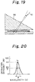
- a wavelength region (half maximum wavelength region) where the diffraction efficiency is half of the maximum diffraction efficiency E p is considered.
- Figs. 21A to 21C show the relationships of the above wavelength region and the heat treatment time period. Figs. 21A to 21C were obtained from the heat treatment at 150°C , but the photosensitive layer may be heat treated at a temperature range in which the photosensitive layer is not burnt, for example, a dichromate gelatin layer may be heat treated at 100 to 170°C.
- Figs. 21A to 21C show that the wavelength of the reconstructing wave becomes constant or stabilized after a heat treatment for 3 to 4 hours; the diffraction efficiency will hardly vary with time; and the half maximum width W tends to be shortened along with an increase in the heating time, i.e., the selectivity is increased. Also, the heat treatment improves the thermal stability and therefore the reliability of a hologram element.
- the hologram elements are made by simultaneously heat treating several dry plates after the exposure. Among the several dry plates, a sample dry plate is selected and the diffraction characteristic of the sample dry plate is observed during the simultaneous heat treating of the several dry plates.
- FIG. 22 several dry plates 721 which were made from the coating of a dichromate gelatin layer to the exposure in the same manner are set in a thermostatic chamber 720 so as to simultaneously heat treat the dry plates 721.
- a sample dry plate 722 is set above the dry plates 721 in the chamber 720.
- An inspection window 723 is provided above the sample dry plate 722 and the sample dry plate 722 is illuminated with a continuous wave of white light (for example, xenon lamp light).
- the diffracted beam 726 diffracted and reflected by the sample dry plate 722 is detected by a sensor 727.
- the detected light is analyzed by a spectrometer, a photometer, etc., to evaluate the diffraction and reflection characteristics.
- the heat treatment is carried out while the above analysis is being conducted.
- the sample dry plate 722 and the dry plate lot 721 are placed as near as possible so as to make the heat treatment conditions thereof substantially identical.
- the above holograms were reflecting type. If the holograms are transmission type, referring to Fig. 22, an inspection window 728 and a sensor 729 are provided below as indicated by the doted line.
- the inspection window 723 or 728 is preferably coated with an anti-reflecting film or is a member which has as low a reflection as possible.
- the data obtained from the analyzers may be processed by a computer so that continuous changes or statistical data may be obtained.
- the heat treatment can be effectively controlled and uniform excellent hologram elements with uniform diffraction characteristics can be obtained.
- Example 8 The other points are the same as in Examples 5 to 7 and the process of Example 8 can be applied to general holograms.
- dry plates 731 after the exposure and development steps are arranged in parallel in a thermostatic chamber 720, in which an inspection window 723 is provided.
- a moving table 732 on which an illumination member 724 and a sensor 727 are mounted is arranged over the inspection window 723. While the table 732 is moved, a continous wave of white light 725 is successively illuminated onto the dry plates 731 and the diffracted light 726 is received by the sensor 727 and analyzed.
- the causes of the fuzzy image or the chromatic aberration include the width ⁇ ⁇ of the diffraction wavelength of a hologram element, the focal length f of a lens recorded in the hologram element, and the size d of the hologram element.
- the chromatic aberration increases, as ⁇ ⁇ increases, f decreases, and d increases.
- 740 denotes an optical source and 741 denotes a hologram element.
- the inventors also discovered that the affect of the above chromatic aberration can be prevented by the constitution as shown in Fig. 7.
- the shape of the upper cover plate 421 is selected to be identical to the diffraction and reflection characteristic of the hologram 41, so that the incident angle ⁇ 1 and emitting angle ⁇ 2 as well as the incident angle ⁇ 1 and the surface reflecting angle ⁇ 2 'are made substantially the same, to thereby eliminate the effect of the chromatic aberration.
- the exposure of a hologram element may include a modification for correcting the chromatic aberration and the shape of the upper cover plate 421 is made to be adapted to the modification.
- Fig. 25 Similar optical components are indicated by the same reference numbers.
- 422 denotes an upper cover plate and 4221 denotes a top surface of the upper cover plate 422.
- FIG. 26 A holography device of this Example is shown in Fig. 26.
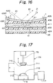
- This holography device is similar to the holography device of Example 5, and is made in the same manner as described in Example 5, except that the upper cover plate 428 is in the form of a planer sheet, not having a concave surface, an anti-reflecting film 429 is provided on the top surface of the upper cover plate 428, and sealants 438 and 439 are a liquid material containing at least two components which are different from each other in one or both of viscosity and refractive index thereof.
- the upper cover plate 428 has a size of 112mm x 46mm x 1.0mm and an anti-reflecting film 429 composed of four layers of alternate MgF2 and TiO2 layers having an apparent percent reflection of 0.3% is coated on the surface of the upper cover plate 428.
- the liquid sealants 438 and 439 are a mixture of a commercially available low refractive index silicone oil (KF56 by Shin-etsu Chemical Industries, with a viscosity of 10cP at 25 °C , and a refractive index of 1.498) and a commercially available highly refractive index silicone oil (HIVACF-4 by Shin-etsu Chemical Industries, with a viscosity of 37cP at 25 °C , and a refractive index of 1.555).
- the mixing ratio of the above two silicone oils is 60:40 by weight so that the refractive index becomes 1.52, identical to that of the glass substrate 411.
- the viscosity of the mixture is 19cP at 25°C .
- a sealant 432 of the above liquid mixture in an amount of 20cm3 is placed on the lower cover plate 424.
- the hologram plate is set with the lower cover plate 424 so one end 411a of the hologram plate is in contact with an end 424a of the lower cover plate 424, then the other end 411b of the hologram plate is gradually lowered at a rate of 10mm/min to assemble them.
- the upper cover plate 428 is similarly assembled with the hologram plate with the sealant inserted therebetween.
- the holography device 40 may be fixed by a casing 47 of a resin, if necessary, as shown in Fig. 28.
- the interfaces of the hologram plate 421 with the upper or lower cover plates 428 and 424 are sealed with a liquid sealant 438 or 432 comprising silicone oils.
- the refractive index of the sealant 438 or 432 can be easily controlled by changing the mixing ratio of the different silicone oils. It is therefore easy to match the refractive index of the sealant with those of the hologram plate 421 and the cover plates 438 and 432.
- the viscosity of the sealant is extremely low. Specifically, the viscosity of the above mixture of the two silicone oils is 19cP at 25°C . In contrast, a conventional epoxy resin-based sealant has a viscosity of 500cP. As a result, with the liquid sealant in Example 11, air bubbles are not entrained in the sealant during the sealing.
- the resin sealant was an epoxy resin-based thermosetting type sealant (CS-2340-5 by Cemedye), which was coated to a thickness of 50 ⁇ m and cured at 120°C for 30 minutes.
- Table 1 shows the characteristics of the silicone oil sealant and the epoxy resin-based sealant.
- Table 1 Silicone oil Epoxy resin Viscosity 10cP at 25°C 500cP at 25°C Refractive index 1.42-1.58, optional 1.55, fixed Curing treatment non Thermosetting Effects on photosensitive medium No reaction heat, no reactivity Reaction heat, reactivity
- the air entaining was evaluated by counting the number of air bubbles for 40 devices and the noise rate was determined by a ratio of the noise image brightness to the normal image brightness in percent. Also, apparent defects were inspected.
- Sample no. 1 corresponds to Example 11 and sample no. 2 corresponds to the comparative example.
- Table 2 Sample no. Air entraining Noise rate Apparent defects 1 0 / 40 0.1% No 2 12 / 40 0.3% 5 peeling-off / 40 devices 3 0 / 40 0.5 % No 4 16 / 40 0.8% 15 peeling-off / 40 devices 30 partial cloud / 40 devices
- a holography device in which the refractive index matching is easy and the deterioration of the photosensitive material is prevented can be provided.
- the silicone oils do not absorb water, which adds an effect that the photosensitive material such as dichromater gelatin is protected from humidity.
- the substrate and cover plates may be transparent resins or films.
- the holography device can be applied to uses other than the head-up display for an automobile.
- the recorded medium in the hologram element may be other optical elements or three dimensional images.
- the constitution of the device may be varied, for example, in the number or shape of the hologram elements or substrates.
- Example 12 is similar to Example 11, except that a commercially available photo-polymer (HR-700 by Dupont) is used for the photosensitive medium of the hologram element.
- HR-700 by Dupont a commercially available photo-polymer
- a commercially available photo-polymer was applied onto a substrate and the cover of the photo-polymer was removed to leave only the photo-polymer on the substrate.
- Example 11 The exposure was effected as in Example 11, to create interference fringes with a pitch of 290 nm.
- the photo-polymer was stabilized by UV irradiation at a total energy of 6J.
- the sealants were the same silicone oils. The other points are the same as in Example 11.
- Sample no. 3 corresponds to Example 12 and sample no. 4 corresponds to a comparative example of Example 12 in which example 12 was repeated but the sealant was the same epoxy resin as used in the comparative example of Example 11.
- Example 12 As is shown in Table 2, the characteristics of the hologram device in Example 12 are remarkably improved in comparison with the conventional device.
- a hologram element other than the photosensitive materials such as a relief, i.e., a work piece processed with a photo-resist to form surface fringe patterns, may be also applied to Examples 5 to 12.
- a relief i.e., a work piece processed with a photo-resist to form surface fringe patterns
- silicone oil in place of silicone oil, other low viscosity liquids such as butyl phthalate (a viscosity of 10cP, a refractive index of 1.49) and xylene which allows the refractive index to be easily controlled by mixing, may be used.
- Examples 11 and 12 the third aspect of the present invention, can be applied to other holography devices such as shown in Figs. 29 and 30.
- an upper cover plate is eliminated and an anti-reflecting film 429 is directly coated onto the surface of the glass substrate 411 of the photosensitive plate 421.
- the glass substrate 411 is eliminated and the photosensitive element 41 is provided on the bottom surface of an upper cover plate 428.
- the other features are the same as in Examples 11 and 12. These examples allow the thickness of the device to be thinner.
Landscapes
- Physics & Mathematics (AREA)
- General Physics & Mathematics (AREA)
- Optics & Photonics (AREA)
- Holo Graphy (AREA)
Priority Applications (1)
| Application Number | Priority Date | Filing Date | Title |
|---|---|---|---|
| EP98101287A EP0840183B1 (de) | 1992-09-03 | 1993-09-03 | Holographievorrichtung |
Applications Claiming Priority (8)
| Application Number | Priority Date | Filing Date | Title |
|---|---|---|---|
| JP26079592 | 1992-09-03 | ||
| JP260795/92 | 1992-09-03 | ||
| JP300529/92 | 1992-10-12 | ||
| JP30052992 | 1992-10-12 | ||
| JP309459/92 | 1992-10-23 | ||
| JP30945992A JPH06138804A (ja) | 1992-10-23 | 1992-10-23 | ホログラムの製造方法 |
| JP215161/93 | 1993-08-05 | ||
| JP21516193A JPH06167615A (ja) | 1992-09-03 | 1993-08-05 | ホログラフィー装置 |
Related Child Applications (1)
| Application Number | Title | Priority Date | Filing Date |
|---|---|---|---|
| EP98101287A Division EP0840183B1 (de) | 1992-09-03 | 1993-09-03 | Holographievorrichtung |
Publications (2)
| Publication Number | Publication Date |
|---|---|
| EP0585941A2 true EP0585941A2 (de) | 1994-03-09 |
| EP0585941A3 EP0585941A3 (en) | 1994-09-21 |
Family
ID=27476727
Family Applications (2)
| Application Number | Title | Priority Date | Filing Date |
|---|---|---|---|
| EP98101287A Expired - Lifetime EP0840183B1 (de) | 1992-09-03 | 1993-09-03 | Holographievorrichtung |
| EP19930114144 Withdrawn EP0585941A3 (en) | 1992-09-03 | 1993-09-03 | Process for making holograms and holography device |
Family Applications Before (1)
| Application Number | Title | Priority Date | Filing Date |
|---|---|---|---|
| EP98101287A Expired - Lifetime EP0840183B1 (de) | 1992-09-03 | 1993-09-03 | Holographievorrichtung |
Country Status (3)
| Country | Link |
|---|---|
| US (1) | US5898511A (de) |
| EP (2) | EP0840183B1 (de) |
| DE (1) | DE69332090T2 (de) |
Cited By (3)
| Publication number | Priority date | Publication date | Assignee | Title |
|---|---|---|---|---|
| DE4447353C1 (de) * | 1994-12-20 | 1996-05-09 | Burczyk Leonhard Dipl Wirtsch | Verfahren zur Herstellung einer transparenten, Strahlung selektiver Wellenlängen reflektierenden Filmschicht |
| US6322932B1 (en) | 1996-08-15 | 2001-11-27 | Lucent Technologies Inc. | Holographic process and media therefor |
| EP1691237A3 (de) * | 2005-02-15 | 2006-10-18 | Fuji Photo Film Co., Ltd. | Holographisches Aufzeichnungsmaterial und holographisches Aufzeichnungsverfahren |
Families Citing this family (79)
| Publication number | Priority date | Publication date | Assignee | Title |
|---|---|---|---|---|
| JP2002236217A (ja) * | 2000-12-08 | 2002-08-23 | Denso Corp | ホログラムスクリーン |
| US20020150022A1 (en) * | 2001-04-12 | 2002-10-17 | Tolmachev Yurii Alexandrovich | Apparatus and method for 3-D storage of information and its retrieval |
| JP2006502421A (ja) * | 2001-11-06 | 2006-01-19 | キーオティ | 画像投影装置 |
| US20030180563A1 (en) * | 2002-02-27 | 2003-09-25 | Canon Kabushiki Kaisha | Optical element and method of manufacturing the same, or laminated optical element and method of manufacturing the same |
| JP4227442B2 (ja) * | 2002-04-18 | 2009-02-18 | キヤノン株式会社 | 光学材料、光学素子、回折光学素子、積層型回折光学素子、光学系及び光学素子の成形方法 |
| US7993285B2 (en) * | 2002-11-05 | 2011-08-09 | Boston Scientific Scimed, Inc. | Medical device having flexible distal tip |
| AU2004262104B2 (en) * | 2003-07-21 | 2007-12-13 | Cambridge University Technical Services Ltd | Holographic sensor |
| JP4407226B2 (ja) * | 2003-10-08 | 2010-02-03 | Tdk株式会社 | ホログラフィック記録媒体及びその製造方法 |
| US20050248817A1 (en) * | 2004-05-07 | 2005-11-10 | Inphase Technologies, Inc. | Covert hologram design, fabrication and optical reconstruction for security applications |
| US20060082850A1 (en) * | 2004-10-18 | 2006-04-20 | Weaver Samuel P | Covert surface relief hologram design, fabrication and optical reconstruction for security applications |
| US7778508B2 (en) * | 2004-12-06 | 2010-08-17 | Nikon Corporation | Image display optical system, image display unit, illuminating optical system, and liquid crystal display unit |
| JPWO2007015298A1 (ja) * | 2005-08-03 | 2009-02-19 | 富士通株式会社 | 光情報記録再生装置および光情報記録媒体 |
| JPWO2007015299A1 (ja) * | 2005-08-03 | 2009-02-19 | 富士通株式会社 | 光情報記録再生装置および光情報記録媒体 |
| GB0718706D0 (en) | 2007-09-25 | 2007-11-07 | Creative Physics Ltd | Method and apparatus for reducing laser speckle |
| JP5128582B2 (ja) * | 2006-05-12 | 2013-01-23 | シーリアル テクノロジーズ ソシエテ アノニム | ホログラフィック投影システム及び方法 |
| JP4847351B2 (ja) * | 2007-01-11 | 2011-12-28 | キヤノン株式会社 | 回折光学素子及びそれを用いた回折格子 |
| JP2008304567A (ja) * | 2007-06-05 | 2008-12-18 | Tdk Corp | ホログラム記録媒体及びその製造方法 |
| EP2277077A1 (de) * | 2008-04-14 | 2011-01-26 | BAE Systems PLC | Laminierung von optischen substraten |
| EP2110700A1 (de) * | 2008-04-14 | 2009-10-21 | BAE Systems PLC | Laminierung von optischen Substraten |
| US11726332B2 (en) | 2009-04-27 | 2023-08-15 | Digilens Inc. | Diffractive projection apparatus |
| US9335604B2 (en) | 2013-12-11 | 2016-05-10 | Milan Momcilo Popovich | Holographic waveguide display |
| US8630041B2 (en) * | 2009-07-17 | 2014-01-14 | International Business Machines Corporation | Data storage assembly with diamond like carbon antireflective layer |
| US8233204B1 (en) | 2009-09-30 | 2012-07-31 | Rockwell Collins, Inc. | Optical displays |
| US10795160B1 (en) | 2014-09-25 | 2020-10-06 | Rockwell Collins, Inc. | Systems for and methods of using fold gratings for dual axis expansion |
| US11300795B1 (en) | 2009-09-30 | 2022-04-12 | Digilens Inc. | Systems for and methods of using fold gratings coordinated with output couplers for dual axis expansion |
| US11320571B2 (en) | 2012-11-16 | 2022-05-03 | Rockwell Collins, Inc. | Transparent waveguide display providing upper and lower fields of view with uniform light extraction |
| US8659826B1 (en) | 2010-02-04 | 2014-02-25 | Rockwell Collins, Inc. | Worn display system and method without requiring real time tracking for boresight precision |
| US9274349B2 (en) | 2011-04-07 | 2016-03-01 | Digilens Inc. | Laser despeckler based on angular diversity |
| US20120288230A1 (en) * | 2011-05-13 | 2012-11-15 | Kestrel Labs, Inc. | Non-Reflective Optical Connections in Laser-Based Photoplethysmography |
| US10670876B2 (en) | 2011-08-24 | 2020-06-02 | Digilens Inc. | Waveguide laser illuminator incorporating a despeckler |
| WO2013027004A1 (en) | 2011-08-24 | 2013-02-28 | Milan Momcilo Popovich | Wearable data display |
| WO2016020630A2 (en) | 2014-08-08 | 2016-02-11 | Milan Momcilo Popovich | Waveguide laser illuminator incorporating a despeckler |
| US9366864B1 (en) | 2011-09-30 | 2016-06-14 | Rockwell Collins, Inc. | System for and method of displaying information without need for a combiner alignment detector |
| US8634139B1 (en) | 2011-09-30 | 2014-01-21 | Rockwell Collins, Inc. | System for and method of catadioptric collimation in a compact head up display (HUD) |
| US9715067B1 (en) | 2011-09-30 | 2017-07-25 | Rockwell Collins, Inc. | Ultra-compact HUD utilizing waveguide pupil expander with surface relief gratings in high refractive index materials |
| US9599813B1 (en) | 2011-09-30 | 2017-03-21 | Rockwell Collins, Inc. | Waveguide combiner system and method with less susceptibility to glare |
| EP2773989A4 (de) * | 2011-11-04 | 2015-10-21 | Univ New York State Res Found | Fotonen-bandlückenstrukturen für multispektrale bildgebungsvorrichtungen |
| US20150010265A1 (en) | 2012-01-06 | 2015-01-08 | Milan, Momcilo POPOVICH | Contact image sensor using switchable bragg gratings |
| US9523852B1 (en) | 2012-03-28 | 2016-12-20 | Rockwell Collins, Inc. | Micro collimator system and method for a head up display (HUD) |
| CN103562802B (zh) | 2012-04-25 | 2016-08-17 | 罗克韦尔柯林斯公司 | 全息广角显示器 |
| US9933684B2 (en) * | 2012-11-16 | 2018-04-03 | Rockwell Collins, Inc. | Transparent waveguide display providing upper and lower fields of view having a specific light output aperture configuration |
| US9674413B1 (en) | 2013-04-17 | 2017-06-06 | Rockwell Collins, Inc. | Vision system and method having improved performance and solar mitigation |
| US9727772B2 (en) | 2013-07-31 | 2017-08-08 | Digilens, Inc. | Method and apparatus for contact image sensing |
| US9244281B1 (en) | 2013-09-26 | 2016-01-26 | Rockwell Collins, Inc. | Display system and method using a detached combiner |
| US10732407B1 (en) | 2014-01-10 | 2020-08-04 | Rockwell Collins, Inc. | Near eye head up display system and method with fixed combiner |
| US9519089B1 (en) | 2014-01-30 | 2016-12-13 | Rockwell Collins, Inc. | High performance volume phase gratings |
| US9244280B1 (en) | 2014-03-25 | 2016-01-26 | Rockwell Collins, Inc. | Near eye display system and method for display enhancement or redundancy |
| WO2016020632A1 (en) | 2014-08-08 | 2016-02-11 | Milan Momcilo Popovich | Method for holographic mastering and replication |
| US10241330B2 (en) | 2014-09-19 | 2019-03-26 | Digilens, Inc. | Method and apparatus for generating input images for holographic waveguide displays |
| US9715110B1 (en) | 2014-09-25 | 2017-07-25 | Rockwell Collins, Inc. | Automotive head up display (HUD) |
| US10088675B1 (en) | 2015-05-18 | 2018-10-02 | Rockwell Collins, Inc. | Turning light pipe for a pupil expansion system and method |
| CN107873086B (zh) | 2015-01-12 | 2020-03-20 | 迪吉伦斯公司 | 环境隔离的波导显示器 |
| US9632226B2 (en) | 2015-02-12 | 2017-04-25 | Digilens Inc. | Waveguide grating device |
| US10126552B2 (en) | 2015-05-18 | 2018-11-13 | Rockwell Collins, Inc. | Micro collimator system and method for a head up display (HUD) |
| US10247943B1 (en) | 2015-05-18 | 2019-04-02 | Rockwell Collins, Inc. | Head up display (HUD) using a light pipe |
| US11366316B2 (en) | 2015-05-18 | 2022-06-21 | Rockwell Collins, Inc. | Head up display (HUD) using a light pipe |
| US10108010B2 (en) | 2015-06-29 | 2018-10-23 | Rockwell Collins, Inc. | System for and method of integrating head up displays and head down displays |
| US10690916B2 (en) | 2015-10-05 | 2020-06-23 | Digilens Inc. | Apparatus for providing waveguide displays with two-dimensional pupil expansion |
| US10598932B1 (en) | 2016-01-06 | 2020-03-24 | Rockwell Collins, Inc. | Head up display for integrating views of conformally mapped symbols and a fixed image source |
| EP3433659B1 (de) | 2016-03-24 | 2024-10-23 | DigiLens, Inc. | Verfahren und vorrichtung zur bereitstellung einer polarisationsselektiven holografischen wellenleitervorrichtung |
| JP6734933B2 (ja) | 2016-04-11 | 2020-08-05 | ディジレンズ インコーポレイテッド | 構造化光投影のためのホログラフィック導波管装置 |
| US11513350B2 (en) | 2016-12-02 | 2022-11-29 | Digilens Inc. | Waveguide device with uniform output illumination |
| US10474103B2 (en) * | 2016-12-27 | 2019-11-12 | Universal City Studios Llc | Holographic image apparatus for high depth of field holograms |
| US10545346B2 (en) | 2017-01-05 | 2020-01-28 | Digilens Inc. | Wearable heads up displays |
| US10295824B2 (en) | 2017-01-26 | 2019-05-21 | Rockwell Collins, Inc. | Head up display with an angled light pipe |
| CN116149058A (zh) | 2017-10-16 | 2023-05-23 | 迪吉伦斯公司 | 用于倍增像素化显示器的图像分辨率的系统和方法 |
| KR20200108030A (ko) | 2018-01-08 | 2020-09-16 | 디지렌즈 인코포레이티드. | 도파관 셀 내의 홀로그래픽 격자의 높은 처리능력의 레코딩을 위한 시스템 및 방법 |
| WO2019136476A1 (en) | 2018-01-08 | 2019-07-11 | Digilens, Inc. | Waveguide architectures and related methods of manufacturing |
| KR20200104402A (ko) | 2018-01-08 | 2020-09-03 | 디지렌즈 인코포레이티드. | 도파관 셀을 제조하기 위한 시스템 및 방법 |
| US11402801B2 (en) | 2018-07-25 | 2022-08-02 | Digilens Inc. | Systems and methods for fabricating a multilayer optical structure |
| JP7087895B2 (ja) * | 2018-10-01 | 2022-06-21 | 株式会社デンソー | 虚像表示装置 |
| KR20210138609A (ko) | 2019-02-15 | 2021-11-19 | 디지렌즈 인코포레이티드. | 일체형 격자를 이용하여 홀로그래픽 도파관 디스플레이를 제공하기 위한 방법 및 장치 |
| JP2022525165A (ja) | 2019-03-12 | 2022-05-11 | ディジレンズ インコーポレイテッド | ホログラフィック導波管バックライトおよび関連する製造方法 |
| JP2020160134A (ja) | 2019-03-25 | 2020-10-01 | セイコーエプソン株式会社 | 表示装置、光学素子及び光学素子の製造方法 |
| CN114207492A (zh) | 2019-06-07 | 2022-03-18 | 迪吉伦斯公司 | 带透射光栅和反射光栅的波导及其生产方法 |
| JP7333721B2 (ja) * | 2019-07-29 | 2023-08-25 | 株式会社日立エルジーデータストレージ | ホログラム導光板、ヘッドマウントディスプレイ |
| KR20220038452A (ko) | 2019-07-29 | 2022-03-28 | 디지렌즈 인코포레이티드. | 픽셀화된 디스플레이의 이미지 해상도와 시야를 증배하는 방법 및 장치 |
| JP7293993B2 (ja) * | 2019-08-29 | 2023-06-20 | セイコーエプソン株式会社 | 表示装置 |
| KR20220054386A (ko) | 2019-08-29 | 2022-05-02 | 디지렌즈 인코포레이티드. | 진공 브래그 격자 및 이의 제조 방법 |
Citations (7)
| Publication number | Priority date | Publication date | Assignee | Title |
|---|---|---|---|---|
| US3560210A (en) * | 1967-01-13 | 1971-02-02 | Ibm | Method of recording a plurality of holograms and separable emulsion exposure package therefor |
| US4209250A (en) * | 1978-12-26 | 1980-06-24 | James Randall P | System for making multiple original holograms or copies of a hologram and method |
| GB2171538A (en) * | 1985-02-27 | 1986-08-28 | Gec Avionics | Making reflection holograms |
| JPH01231082A (ja) * | 1988-03-11 | 1989-09-14 | Canon Inc | 体積立相ホログラムの製造方法 |
| GB2234605A (en) * | 1989-07-31 | 1991-02-06 | British Telecomm | A holographic element |
| JPH03188479A (ja) * | 1989-12-18 | 1991-08-16 | Fujitsu Ltd | 反射型ホログラムの複製方法 |
| JPH03188478A (ja) * | 1989-12-18 | 1991-08-16 | Fujitsu Ltd | ホログラムの作成方法 |
Family Cites Families (19)
| Publication number | Priority date | Publication date | Assignee | Title |
|---|---|---|---|---|
| US4582389A (en) * | 1982-02-18 | 1986-04-15 | Flight Dynamics, Inc. | Holographic device |
| FR2542459B1 (fr) * | 1983-03-07 | 1987-01-30 | Thomson Csf | Viseur tete haute |
| US4786125A (en) * | 1983-08-22 | 1988-11-22 | Farrand Optical Co. | Ocular protective apparatus |
| US4613200A (en) * | 1984-07-09 | 1986-09-23 | Ford Motor Company | Heads-up display system with holographic dispersion correcting |
| JPS6129508A (ja) * | 1984-07-10 | 1986-02-10 | Sumitomo Rubber Ind Ltd | タイヤの加硫成型方法 |
| US4815800A (en) * | 1984-12-21 | 1989-03-28 | Hughes Aircraft Company | Flare reduction in holograms |
| DE3532120A1 (de) * | 1985-09-10 | 1987-03-19 | Ver Glaswerke Gmbh | Windschutzscheibe mit einer reflektierenden einrichtung zur einspiegelung von optischen signalen in das gesichtsfeld des fahrers |
| US4863225A (en) * | 1986-03-26 | 1989-09-05 | Gec Avionics Limited | Reflection holograms formed by scanning |
| JP2556020B2 (ja) * | 1987-02-06 | 1996-11-20 | 日本電装株式会社 | ホログラムを用いた表示装置 |
| FR2614434B1 (fr) * | 1987-04-22 | 1989-06-09 | Thomson Csf | Viseur clair holographique montable sur casque |
| JPS6440883A (en) * | 1987-08-07 | 1989-02-13 | Canon Kk | Hologram having protective layer |
| US4953923A (en) * | 1988-08-01 | 1990-09-04 | Hughes Aircraft Company | System for reducing noise holograms |
| US5105287A (en) * | 1989-05-03 | 1992-04-14 | Hughes Aircraft Company | Reduction of holographic noise with short laser pulses |
| US4981332A (en) * | 1989-06-29 | 1991-01-01 | Hughes Aircraft Company | Dispersion-compensated windshield hologram virtual image display |
| US5243449A (en) * | 1990-12-13 | 1993-09-07 | Hughes Aircraft Company | Ambient turn-on suppression hologram |
| JPH04329585A (ja) * | 1991-05-01 | 1992-11-18 | Nippondenso Co Ltd | 光学素子コピー用反射型ホログラム乾板製造装置 |
| US5282066A (en) * | 1991-05-31 | 1994-01-25 | Hughes Aircraft Company | Multiple layer holograms |
| US5198914A (en) * | 1991-11-26 | 1993-03-30 | Hughes Aircraft Company | Automatic constant wavelength holographic exposure system |
| US5307438A (en) * | 1992-08-13 | 1994-04-26 | Minnesota Mining And Manufacturing Company | Index matching compositions with improved DNG/DT |
-
1993
- 1993-09-03 EP EP98101287A patent/EP0840183B1/de not_active Expired - Lifetime
- 1993-09-03 EP EP19930114144 patent/EP0585941A3/en not_active Withdrawn
- 1993-09-03 DE DE69332090T patent/DE69332090T2/de not_active Expired - Lifetime
-
1995
- 1995-02-06 US US08/384,800 patent/US5898511A/en not_active Expired - Lifetime
Patent Citations (7)
| Publication number | Priority date | Publication date | Assignee | Title |
|---|---|---|---|---|
| US3560210A (en) * | 1967-01-13 | 1971-02-02 | Ibm | Method of recording a plurality of holograms and separable emulsion exposure package therefor |
| US4209250A (en) * | 1978-12-26 | 1980-06-24 | James Randall P | System for making multiple original holograms or copies of a hologram and method |
| GB2171538A (en) * | 1985-02-27 | 1986-08-28 | Gec Avionics | Making reflection holograms |
| JPH01231082A (ja) * | 1988-03-11 | 1989-09-14 | Canon Inc | 体積立相ホログラムの製造方法 |
| GB2234605A (en) * | 1989-07-31 | 1991-02-06 | British Telecomm | A holographic element |
| JPH03188479A (ja) * | 1989-12-18 | 1991-08-16 | Fujitsu Ltd | 反射型ホログラムの複製方法 |
| JPH03188478A (ja) * | 1989-12-18 | 1991-08-16 | Fujitsu Ltd | ホログラムの作成方法 |
Non-Patent Citations (6)
| Title |
|---|
| IBM TECHNICAL DISCLOSURE BULLETIN, vol.10, no.12, May 1968, NEW YORK US page 1895 'MULTIPRODUCTION OF HOLOGRAMS' * |
| OPTICS LETTERS, vol.17, no.23, 1 December 1992, WASHINGTON US pages 1709 - 1711 GREGORY P. NORDIN ET AL. 'PHOTOPOLYMER-BASED STRATIFIED VOLUME HOLOGRAPHIC OPTICAL ELEMENTS' * |
| PATENT ABSTRACTS OF JAPAN vol. 13, no. 554 (P-973) 11 December 1989 & JP-A-01 231 082 (CANON INC) * |
| PATENT ABSTRACTS OF JAPAN vol. 15, no. 449 (P-1275) 14 November 1991 & JP-A-03 188 478 (FUJITSU LTD) * |
| PATENT ABSTRACTS OF JAPAN vol. 15, no. 449 (P-1275) 14 November 1991 & JP-A-03 188 479 (FUJITSU LTD) * |
| RESEARCH DISCLOSURE, no.317, September 1990, HAVANT GB page 762 DISCL.NO. 31772 'EXPOSURE OF HOLOGRAMS ON LOW OPTICAL QUALITY SUBSTRATES' * |
Cited By (3)
| Publication number | Priority date | Publication date | Assignee | Title |
|---|---|---|---|---|
| DE4447353C1 (de) * | 1994-12-20 | 1996-05-09 | Burczyk Leonhard Dipl Wirtsch | Verfahren zur Herstellung einer transparenten, Strahlung selektiver Wellenlängen reflektierenden Filmschicht |
| US6322932B1 (en) | 1996-08-15 | 2001-11-27 | Lucent Technologies Inc. | Holographic process and media therefor |
| EP1691237A3 (de) * | 2005-02-15 | 2006-10-18 | Fuji Photo Film Co., Ltd. | Holographisches Aufzeichnungsmaterial und holographisches Aufzeichnungsverfahren |
Also Published As
| Publication number | Publication date |
|---|---|
| DE69332090T2 (de) | 2002-10-17 |
| DE69332090D1 (de) | 2002-08-08 |
| US5898511A (en) | 1999-04-27 |
| EP0585941A3 (en) | 1994-09-21 |
| EP0840183B1 (de) | 2002-07-03 |
| EP0840183A2 (de) | 1998-05-06 |
| EP0840183A3 (de) | 1998-05-13 |
Similar Documents
| Publication | Publication Date | Title |
|---|---|---|
| EP0840183B1 (de) | Holographievorrichtung | |
| EP0760490B1 (de) | Bildanzeigevorrichtung | |
| EP0764282B1 (de) | Holographische mehrfarbige optische elemente zur verwendung in flüssigkristallanzeigen und methoden zu deren herstellung | |
| EP0349947B1 (de) | Beugungsoptisches Streuschirmlaminat für vollfarbfähige Axialbetrachtung | |
| EP0764283B1 (de) | Farbabgestimmte holographische optische elemente und verfahren zu deren herstellung | |
| US6166834A (en) | Display apparatus and method for forming hologram suitable for the display apparatus | |
| US5721630A (en) | High-efficiency reflective holographic diffuser and method for making thereof | |
| US20050259302A9 (en) | Holographic light panels and flat panel display systems and method and apparatus for making same | |
| JP2004318038A (ja) | ディスプレー用ライトユニット | |
| GB2260203A (en) | Transmissive colour display system illuminated using a holographic element | |
| EP1949184B1 (de) | Für die ultraviolett-spektralregion optimiertes holografisches volumen-phasen-beugungsgitter | |
| US6924912B2 (en) | Holographic screen | |
| US6081354A (en) | Holographic reflector for liquid crystal display | |
| US20020001110A1 (en) | Holographic light panels and flat panel display systems and method and apparatus for making same | |
| JP3321849B2 (ja) | ホログラム | |
| JPH06167615A (ja) | ホログラフィー装置 | |
| Ueda et al. | Edge-illuminated color holograms | |
| JPH0713475A (ja) | ホログラムの製造方法 | |
| JP2001330732A (ja) | カラー反射板およびそれを用いた反射型液晶表示素子 | |
| CN118625509A (zh) | 一种瞄准镜光路系统 | |
| JPH10254334A (ja) | 拡散反射型ホログラムの複製方法及びそれに用いる拡散反射型ホログラム複製用原版 | |
| JP3391044B2 (ja) | ホログラムの製造方法 | |
| JPH06195016A (ja) | ホログラフィー装置 | |
| JPH06138804A (ja) | ホログラムの製造方法 | |
| JPH10206639A (ja) | ホログラム反射板とそれを用いた反射型液晶表示装置 |
Legal Events
| Date | Code | Title | Description |
|---|---|---|---|
| PUAI | Public reference made under article 153(3) epc to a published international application that has entered the european phase |
Free format text: ORIGINAL CODE: 0009012 |
|
| AK | Designated contracting states |
Kind code of ref document: A2 Designated state(s): DE FR GB |
|
| PUAL | Search report despatched |
Free format text: ORIGINAL CODE: 0009013 |
|
| AK | Designated contracting states |
Kind code of ref document: A3 Designated state(s): DE FR GB |
|
| 17P | Request for examination filed |
Effective date: 19950117 |
|
| 17Q | First examination report despatched |
Effective date: 19961001 |
|
| RAP1 | Party data changed (applicant data changed or rights of an application transferred) |
Owner name: DENSO CORPORATION |
|
| APAB | Appeal dossier modified |
Free format text: ORIGINAL CODE: EPIDOS NOAPE |
|
| APAB | Appeal dossier modified |
Free format text: ORIGINAL CODE: EPIDOS NOAPE |
|
| APBJ | Interlocutory revision of appeal recorded |
Free format text: ORIGINAL CODE: EPIDOS IRAPE |
|
| STAA | Information on the status of an ep patent application or granted ep patent |
Free format text: STATUS: THE APPLICATION IS DEEMED TO BE WITHDRAWN |
|
| 18D | Application deemed to be withdrawn |
Effective date: 19980904 |