EP0585555A2 - Mécanisme pour insérer un fil dans un appareil de contrôle de fil - Google Patents
Mécanisme pour insérer un fil dans un appareil de contrôle de fil Download PDFInfo
- Publication number
- EP0585555A2 EP0585555A2 EP93110581A EP93110581A EP0585555A2 EP 0585555 A2 EP0585555 A2 EP 0585555A2 EP 93110581 A EP93110581 A EP 93110581A EP 93110581 A EP93110581 A EP 93110581A EP 0585555 A2 EP0585555 A2 EP 0585555A2
- Authority
- EP
- European Patent Office
- Prior art keywords
- thread
- clamp
- arm
- insertion arm
- mechanism according
- Prior art date
- Legal status (The legal status is an assumption and is not a legal conclusion. Google has not performed a legal analysis and makes no representation as to the accuracy of the status listed.)
- Granted
Links
Images

Classifications
-
- G—PHYSICS
- G01—MEASURING; TESTING
- G01N—INVESTIGATING OR ANALYSING MATERIALS BY DETERMINING THEIR CHEMICAL OR PHYSICAL PROPERTIES
- G01N3/00—Investigating strength properties of solid materials by application of mechanical stress
- G01N3/08—Investigating strength properties of solid materials by application of mechanical stress by applying steady tensile or compressive forces
-
- G—PHYSICS
- G01—MEASURING; TESTING
- G01N—INVESTIGATING OR ANALYSING MATERIALS BY DETERMINING THEIR CHEMICAL OR PHYSICAL PROPERTIES
- G01N33/00—Investigating or analysing materials by specific methods not covered by groups G01N1/00 - G01N31/00
- G01N33/36—Textiles
- G01N33/365—Textiles filiform textiles, e.g. yarns
-
- G—PHYSICS
- G01—MEASURING; TESTING
- G01N—INVESTIGATING OR ANALYSING MATERIALS BY DETERMINING THEIR CHEMICAL OR PHYSICAL PROPERTIES
- G01N2203/00—Investigating strength properties of solid materials by application of mechanical stress
- G01N2203/02—Details not specific for a particular testing method
- G01N2203/026—Specifications of the specimen
- G01N2203/0262—Shape of the specimen
- G01N2203/0278—Thin specimens
- G01N2203/028—One dimensional, e.g. filaments, wires, ropes or cables
Definitions
- the present invention relates to a mechanism for inserting a thread into a yarn testing device, which has a test section and a take-over element for the inserted thread, with an insertion arm and a clamp for presenting the thread thereon.
- a yarn testing device of this type is, for example, the tear strength testing device USTER TENSOJET (USTER - registered trademark of Zellweger Uster AG) described in EP-A-403 988, in which the test material is stretched by means of two mutually spaced, rotating roller pairs, a periodic between the rollers of which opening and closing clamping gap is formed for the test material.
- This testing system is characterized, among other things, by a very high testing speed, which, especially when testing yarn of different bobbins, requires an appropriate insertion mechanism for the threads to be tested.
- the invention is now to provide an insertion mechanism which has a high insertion frequency and is as simple as possible Thread transfer to the takeover organ, and which is characterized by a small space requirement.
- the insertion arm is designed as a fixedly mounted swivel arm and the thread is fixed in the clamp until it is transferred to the take-over element and is fed to the take-over element as a loop.
- the stationary mounting of the insertion arm and its design as a swivel arm means that the thread presented to the insertion arm is pulled out in a simple swivel movement and fed to the take-over element.
- the loop pull-out means that no thread clamp is required on the insert arm itself, so that it can be designed very easily.
- the transfer of the loop-shaped thread to the takeover element also requires little effort. If, for example, the takeover element is designed as an air nozzle, preferably as a suction nozzle, then it is sufficient to position the thread transversely to its inlet opening, which is very simple with a thread loop.
- the small space requirement of the insertion mechanism according to the invention is obvious.
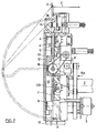
- Fig. 1 shows a front view of the feed part of a tear strength testing system, as described in EP-A-403 988.
- the thread F to be tested is fed to the feed part from above, passes through it from top to bottom and then arrives in the inlet section (not shown) of the actual test part of the test system.
- the test part reference is made to EP-A-403 988.
- a yarn changer 1 is arranged on the upper edge of the feed part, which consists of thread guide eyelets 2 and yarn clamps 3 arranged side by side. These form a terminal block which can be shifted gradually in the direction of arrow A, with, for example, 12 thread guide eyelets 2 and thread clamps 3 each.
- the bobbins to be tested are plugged onto a bobbin memory of the type described, for example, in Swiss Patent Application No. 2072/90, and the threads are removed by hand inserted in the guide eyes 2 and yarn clamps 3 and are stretched between them.
- the clamped threads can be gripped at their free piece between the thread guide eyelet 2 and the thread clamp 3 by a suitable insertion member and pulled off by the thread guide eyelets 2.
- a pair of scissors 4 is arranged in the thread running direction, after this a traversing element 5 and then a pair of motor-driven delivery rollers 6, with which the thread F is continuously withdrawn from its supply in the test mode.
- the traversing element 5 is driven back and forth perpendicular to the plane of the drawing and thereby guides the thread F between the delivery rollers 6 forwards and backwards, which ensures a uniform load on the delivery rollers 6 and thus a perfect thread take-off.
- a thread store is provided between the delivery rollers 6 and the test part.
- This comprises a pneumatic thread store 7, as is known, for example, from air jet weaving machines, and a controlled thread clamp 8, which consists of a continuously driven control roller with a graduated circumference and a freely rotatable counter roller.
- the controlled thread clamp 8 enables the thread store 7 to be emptied in a controlled manner, the thread F being either clamped or released by the thread clamp 8 because of the stepped circumference of the control roller.
- the drive of the control roller is coupled to that of the delivery rollers 6 via a belt drive RA.
- Reference number 9 denotes an incremental encoder for the control roller of the thread clamp 8.
- the organs scissors 4, traversing element 5, delivery rollers 6, thread store 7 and controlled thread clamp 8 are arranged in a flat housing, which is formed by a milled step 10 and a plate 11 and forward through a transparent swing door 12 is complete.
- the thread store 7 extends from the bottom of this gradation to the rear, and the other organs mentioned transfer the ground and extend almost to the pivot door 12.
- a suction nozzle 13 is inserted, the longitudinal axis of which is included the thread F is aligned, and which is used to convey the thread F from the thread store 7 into a thread guide channel of the test part of the test system.
- the thread F in question is inserted into the feed part and brought up to the nozzle 13, from which it is then pneumatically conveyed into the test part.
- the insertion is carried out by a mechanism which consists essentially of two components, from the yarn changer 1 already described and from an insertion arm 14.
- the latter is needle-shaped and has an approximately L-shaped shape with a longer and a shorter leg offset from this .
- the longer leg is on one in one Bearing bracket 15 mounted disc-like or block-like support 16 which is motor-driven via a toothed belt 17 (Fig. 2).
- the shorter leg carries at its free end a finger 18 to which a thread guide 19 is attached.
- the longer leg extends in the thread running direction, the shorter leg transversely to this.
- FIG. 1 and 2 show the insertion arm 14 in two positions, namely in the rest position and in the working position, which have an angular distance of 180 °, and between which the insertion arm 14 can be pivoted by its drive.
- Fig. 1 the rest position and in Fig. 2 the working position is drawn with solid lines.
- the thread guide 19 lies approximately at the level of the bottom of the gradation 10 and thus behind the thread F.
- the insertion arm 14 protrudes above the gradation 10 and the thread guide 19 is in the thread changer 1 between the thread guide eyelet 2 and the thread clamp 3 positioned.
- the thread guide 19 lies just above the suction nozzle 13.
- a groove 20 milled into the bottom of the gradation 10 and surrounding the insert arm 14 with a stepped depth enables the insert arm 14 to be pivoted to the level of the base mentioned.
- a microswitch 21, 22 projecting above this base is arranged in the bottom of the groove 20 on both sides of the carrier 16, by its actuation the motor driving the carrier 16 via the toothed belt 17 is stopped and a signal indicating that the insert arm 14 has reached the working or rest position is generated.
- the system is prepared for testing a series of threads F; the threads were inserted by hand into the yarn changer 1 and the insertion arm 14 is in its rest position, in which it has remained since the last insertion operation.
- the delivery rollers 6 are pivoted slightly apart so that a gap is formed between them, and the controlled thread clamp 8 is open. Pressing the start button activates the suction nozzle 13 on the one hand, and on the other hand the insertion arm 14 swivels into its working position (FIG. 2), the reaching of which is signaled by the microswitch 21.
- the yarn changer 1 is shifted to the right by one step in the direction of arrow A, as a result of which the thread F of the foremost cell of the yarn changer 1 formed from the thread guide eyelet 2 and the thread clamp 3 is presented to the thread guide 19.
- the length of the work step of the yarn changer 1 corresponds to half the mutual distance of the threads clamped in it.
- this thread Since this thread is fixed in the thread clamp 3, it is pulled out of the thread guide eyelet 2 as a loop during the pivoting movement of the insertion arm 14, its section stretched between the thread clamp 3 and the thread guide 19 is moved like a pointer against the connecting axis between the gap between the delivery rollers 6 and the open clamping gap of the controlled thread clamp 8.
- said section of the thread F is first placed in the controlled thread clamp 8 and then between the delivery rollers 6 until finally the thread guide 19 passes over the inlet opening of the suction nozzle 13 and the thread F is exposed to the suction of the nozzle becomes.
- the insertion arm 14 reaches its rest position, which is signaled by the microswitch 22.
- the yarn clamp 3 is opened and on the other hand the delivery rollers 6 are started and pivoted against each other and the thread F is now drawn from its supply by the latter and fed to the test section through the suction nozzle 13.
- the thread store 7 is activated at the same time.
- the yarn clamp 3 is closed and the yarn changer 1 is shifted by one work step in the direction of arrow A.
- the delivery rollers 6 are pivoted away from one another and stopped.
- the drive of the controlled thread clamp 8 is stopped, in such a way that the clamp is open, and the thread store 7 is also switched off.
- the thread F is now in the effective range of the scissors 4 and is cut off by this. The cut end of the thread is sucked off from the nozzle 13.
- the system is thus ready for a further test, which begins with the pivoting back of the insertion arm 14 into the working position.
- the pivot door 12 is opened before the pivoting of the insertion arm 14 into the working position; this remains open until the insertion arm 14 has reached its rest position and is then automatically closed.
- the opening of the door 12 is triggered by the actuation of the start button, the closing by the microswitch 22.
Applications Claiming Priority (4)
| Application Number | Priority Date | Filing Date | Title |
|---|---|---|---|
| CH2187/92 | 1992-07-10 | ||
| CH218792 | 1992-07-10 | ||
| CH218792A CH685649A5 (de) | 1992-07-10 | 1992-07-10 | Mechanismus zum Einlegen eines Fadens in ein Garnprüfgerät. |
| US08/090,009 US5351535A (en) | 1992-07-10 | 1993-07-12 | Mechanism for inserting a thread into a yarn tester |
Publications (3)
| Publication Number | Publication Date |
|---|---|
| EP0585555A2 true EP0585555A2 (fr) | 1994-03-09 |
| EP0585555A3 EP0585555A3 (fr) | 1994-11-23 |
| EP0585555B1 EP0585555B1 (fr) | 1999-10-06 |
Family
ID=25689750
Family Applications (1)
| Application Number | Title | Priority Date | Filing Date |
|---|---|---|---|
| EP93110581A Expired - Lifetime EP0585555B1 (fr) | 1992-07-10 | 1993-07-02 | Mécanisme pour insérer un fil dans un appareil de contrÔle de fil |
Country Status (4)
| Country | Link |
|---|---|
| US (1) | US5351535A (fr) |
| EP (1) | EP0585555B1 (fr) |
| JP (1) | JP3263748B2 (fr) |
| CN (1) | CN1038066C (fr) |
Cited By (3)
| Publication number | Priority date | Publication date | Assignee | Title |
|---|---|---|---|---|
| CN103822779A (zh) * | 2014-02-22 | 2014-05-28 | 咸阳经纬纺织机械有限公司 | 主喷嘴综合质量测试系统及测试方法 |
| WO2016149845A1 (fr) * | 2015-03-20 | 2016-09-29 | Uster Technologies Ag | Dispositif de changement de fil semi-automatique pour un appareil de test de fil |
| WO2016149841A1 (fr) * | 2015-03-20 | 2016-09-29 | Uster Technologies Ag | Appareil de contrôle de fil muni d'un dispositif d'introduction de fil |
Families Citing this family (5)
| Publication number | Priority date | Publication date | Assignee | Title |
|---|---|---|---|---|
| CN1313343C (zh) * | 2000-11-09 | 2007-05-02 | 苏拉有限及两合公司 | 卷曲变形机和用于行进中的长丝生头的方法 |
| DE102009030880A1 (de) | 2009-06-29 | 2010-12-30 | Oerlikon Textile Gmbh & Co. Kg | Fadenbehandlungsvorrichtung |
| WO2016149840A1 (fr) * | 2015-03-20 | 2016-09-29 | Uster Technologies Ag | Appareil de contrôle de fil modulaire |
| ITUB20154807A1 (it) * | 2015-10-20 | 2017-04-20 | Mesdan Spa | Dispositivo di misurazione per la misurazione di caratteristiche dinamometriche di campioni tessili allungati del tipo di filati, fili, nastri e simili |
| ITUB20155052A1 (it) | 2015-10-20 | 2017-04-20 | Mesdan Spa | Apparecchiatura modulare per la determinazione automatica di caratteristiche di campioni tessili allungati del tipo di filati, fili, nastri e simili. |
Citations (4)
| Publication number | Priority date | Publication date | Assignee | Title |
|---|---|---|---|---|
| AT181101B (de) * | 1950-04-14 | 1955-02-25 | Zellweger Uster Ag | Einrichtung zum Zuführen einzelner Längen von Fäden u. dgl. an Fadenprüfmaschinen |
| DE1905161A1 (de) * | 1968-02-05 | 1969-08-28 | Leesona Corp | Vorrichtung zur Fuehrung eines Garnfadens |
| DE3012499A1 (de) * | 1979-09-19 | 1981-04-02 | Zellweger Uster AG, 8610 Uster | Vorrichtung zum einlegen eines fadens in die pruefstrecke von reissfestigkeitspruefgeraeten |
| EP0403988A2 (fr) * | 1989-06-20 | 1990-12-27 | Zellweger Luwa Ag | Dispositif pour la détermination des propriétés mécaniques d'un échantillon textile allongé |
Family Cites Families (10)
| Publication number | Priority date | Publication date | Assignee | Title |
|---|---|---|---|---|
| US1358793A (en) * | 1917-10-02 | 1920-11-16 | United Sroe Machinery Corp | Feeding device |
| DE824861C (de) * | 1950-04-14 | 1951-12-13 | Zellweger A G App Und Maschine | Einrichtung zum Zufuehren und Pruefen einzelner Laengen von Faeden u. dgl. in Fadenpruefmaschinen |
| GB1306808A (en) * | 1969-12-22 | 1973-02-14 | Turner Brothers Asbest | Methods of and apparatus for conveying thread |
| US3741050A (en) * | 1970-05-27 | 1973-06-26 | Ici Ltd | Method of stringing a thread through a hole |
| US3805607A (en) * | 1971-08-27 | 1974-04-23 | Zellweger Uster Ag | Yarn changing mechanism |
| US3751981A (en) * | 1971-11-15 | 1973-08-14 | Celanese Corp | Yarn measuring and yarn feeding therefor |
| US3822539A (en) * | 1972-10-24 | 1974-07-09 | Ici Ltd | Threadable yarn treatment tube |
| US4169551A (en) * | 1978-02-28 | 1979-10-02 | Ppg Industries, Inc. | Apparatus for threading moving strands |
| GB2130157B (en) * | 1982-11-09 | 1986-02-19 | Latchways Ltd | Threading device |
| US5203206A (en) * | 1989-01-04 | 1993-04-20 | Zellweger Uster, Inc. | Apparatus and methods for testing tension-elongation or cross-sectional properties of single fibers and multiple fiber bundles |
-
1993
- 1993-06-24 JP JP19505993A patent/JP3263748B2/ja not_active Expired - Fee Related
- 1993-07-02 EP EP93110581A patent/EP0585555B1/fr not_active Expired - Lifetime
- 1993-07-10 CN CN93108423A patent/CN1038066C/zh not_active Expired - Fee Related
- 1993-07-12 US US08/090,009 patent/US5351535A/en not_active Expired - Lifetime
Patent Citations (4)
| Publication number | Priority date | Publication date | Assignee | Title |
|---|---|---|---|---|
| AT181101B (de) * | 1950-04-14 | 1955-02-25 | Zellweger Uster Ag | Einrichtung zum Zuführen einzelner Längen von Fäden u. dgl. an Fadenprüfmaschinen |
| DE1905161A1 (de) * | 1968-02-05 | 1969-08-28 | Leesona Corp | Vorrichtung zur Fuehrung eines Garnfadens |
| DE3012499A1 (de) * | 1979-09-19 | 1981-04-02 | Zellweger Uster AG, 8610 Uster | Vorrichtung zum einlegen eines fadens in die pruefstrecke von reissfestigkeitspruefgeraeten |
| EP0403988A2 (fr) * | 1989-06-20 | 1990-12-27 | Zellweger Luwa Ag | Dispositif pour la détermination des propriétés mécaniques d'un échantillon textile allongé |
Cited By (3)
| Publication number | Priority date | Publication date | Assignee | Title |
|---|---|---|---|---|
| CN103822779A (zh) * | 2014-02-22 | 2014-05-28 | 咸阳经纬纺织机械有限公司 | 主喷嘴综合质量测试系统及测试方法 |
| WO2016149845A1 (fr) * | 2015-03-20 | 2016-09-29 | Uster Technologies Ag | Dispositif de changement de fil semi-automatique pour un appareil de test de fil |
| WO2016149841A1 (fr) * | 2015-03-20 | 2016-09-29 | Uster Technologies Ag | Appareil de contrôle de fil muni d'un dispositif d'introduction de fil |
Also Published As
| Publication number | Publication date |
|---|---|
| EP0585555B1 (fr) | 1999-10-06 |
| JP3263748B2 (ja) | 2002-03-11 |
| US5351535A (en) | 1994-10-04 |
| EP0585555A3 (fr) | 1994-11-23 |
| CN1087597A (zh) | 1994-06-08 |
| JPH0666697A (ja) | 1994-03-11 |
| CN1038066C (zh) | 1998-04-15 |
Similar Documents
| Publication | Publication Date | Title |
|---|---|---|
| DE19722395C1 (de) | Nähmaschine mit einer Fadenschneideinrichtung | |
| DE2332327C3 (de) | Vorrichtung zum Zuführen, Abtrennen und Anspülen des Fadenanfanges an eine laufende Spule | |
| DE2939644C2 (de) | Verfahren und Vorrichtung zur Beseitigung einer Unregelmäßigkeit am laufenden Faden an einer Offenend-Spinnstelle während des Spinnens | |
| EP0054775B1 (fr) | Dispositif de tri de bobines coniques | |
| DE1585392C3 (de) | Vorrichtung zum Anliefern von Schußfäden zu einer Kettenwirkmaschine | |
| DE2810741A1 (de) | Verfahren und vorrichtung zum verbinden eines oberfadens mit einem unterfaden | |
| DE2922694A1 (de) | Verfahren und vorrichtung zum verbinden eines oberfadens mit einem unterfaden | |
| EP0585555B1 (fr) | Mécanisme pour insérer un fil dans un appareil de contrÔle de fil | |
| EP0129043A2 (fr) | Dispositif et procédé pour piquer des motifs sur par exemple, des oreillers | |
| EP0453543B1 (fr) | Appareil pour retourner les bas automatiquement pour une machine a remailler | |
| DE3305479A1 (de) | Verfahren und vorrichtung zum pneumatischen spleissen gesponnener faeden | |
| DE2847520C3 (de) | Vorrichtung zum Vorlegen von Kettfäden für das automatische Einziehen derselben in Litzen und Lamellen einer Webmaschine | |
| DE2856871A1 (de) | Verfahren und vorrichtung zur herstellung kontinuierlich bestickter stoffe | |
| DE2737197C2 (de) | Düsenwebmaschine | |
| DE3844043C2 (fr) | ||
| CH685649A5 (de) | Mechanismus zum Einlegen eines Fadens in ein Garnprüfgerät. | |
| DE3830772C2 (fr) | ||
| DE2514794A1 (de) | Automatische einrichtung zum zusammennaehen zweier elastischer stoffteile mit unterschiedlicher elastizitaet | |
| DE2041043C3 (de) | Vorschubvorrichtung für eine der Bereithaltung einer Anzahl von einer Prüfung zu unterziehender Garne dienenden Garnwechselvorrichtung | |
| DE3132894C2 (fr) | ||
| CH681900A5 (fr) | ||
| DE2815999C2 (fr) | ||
| EP0333190A2 (fr) | Dispositif pour l'alimentation sélective d'un parmi plusieurs fils de trame à une navette à pince | |
| DE1914397B2 (de) | Eintragnadel einer webmaschine | |
| DE3843399A1 (de) | Luftwebmaschine mit einer vorrichtung zur entfernung eines fehlerhaften schussfadens aus dem webfach |
Legal Events
| Date | Code | Title | Description |
|---|---|---|---|
| PUAI | Public reference made under article 153(3) epc to a published international application that has entered the european phase |
Free format text: ORIGINAL CODE: 0009012 |
|
| AK | Designated contracting states |
Kind code of ref document: A2 Designated state(s): BE DE ES FR GB IT |
|
| RAP1 | Party data changed (applicant data changed or rights of an application transferred) |
Owner name: ZELLWEGER LUWA AG |
|
| PUAL | Search report despatched |
Free format text: ORIGINAL CODE: 0009013 |
|
| RHK1 | Main classification (correction) |
Ipc: G01N 3/04 |
|
| AK | Designated contracting states |
Kind code of ref document: A3 Designated state(s): BE DE ES FR GB IT |
|
| 17P | Request for examination filed |
Effective date: 19950518 |
|
| GRAG | Despatch of communication of intention to grant |
Free format text: ORIGINAL CODE: EPIDOS AGRA |
|
| 17Q | First examination report despatched |
Effective date: 19980821 |
|
| GRAG | Despatch of communication of intention to grant |
Free format text: ORIGINAL CODE: EPIDOS AGRA |
|
| GRAH | Despatch of communication of intention to grant a patent |
Free format text: ORIGINAL CODE: EPIDOS IGRA |
|
| GRAH | Despatch of communication of intention to grant a patent |
Free format text: ORIGINAL CODE: EPIDOS IGRA |
|
| GRAA | (expected) grant |
Free format text: ORIGINAL CODE: 0009210 |
|
| AK | Designated contracting states |
Kind code of ref document: B1 Designated state(s): BE DE ES FR GB IT |
|
| PG25 | Lapsed in a contracting state [announced via postgrant information from national office to epo] |
Ref country code: ES Free format text: THE PATENT HAS BEEN ANNULLED BY A DECISION OF A NATIONAL AUTHORITY Effective date: 19991006 |
|
| GBT | Gb: translation of ep patent filed (gb section 77(6)(a)/1977) |
Effective date: 19991006 |
|
| ITF | It: translation for a ep patent filed |
Owner name: FIAMMENGHI - DOMENIGHETTI |
|
| REF | Corresponds to: |
Ref document number: 59309816 Country of ref document: DE Date of ref document: 19991111 |
|
| ET | Fr: translation filed | ||
| PLBE | No opposition filed within time limit |
Free format text: ORIGINAL CODE: 0009261 |
|
| STAA | Information on the status of an ep patent application or granted ep patent |
Free format text: STATUS: NO OPPOSITION FILED WITHIN TIME LIMIT |
|
| 26N | No opposition filed | ||
| REG | Reference to a national code |
Ref country code: GB Ref legal event code: IF02 |
|
| PGFP | Annual fee paid to national office [announced via postgrant information from national office to epo] |
Ref country code: GB Payment date: 20020626 Year of fee payment: 10 |
|
| PG25 | Lapsed in a contracting state [announced via postgrant information from national office to epo] |
Ref country code: GB Free format text: LAPSE BECAUSE OF NON-PAYMENT OF DUE FEES Effective date: 20030702 |
|
| REG | Reference to a national code |
Ref country code: FR Ref legal event code: TP |
|
| GBPC | Gb: european patent ceased through non-payment of renewal fee |
Effective date: 20030702 |
|
| PGFP | Annual fee paid to national office [announced via postgrant information from national office to epo] |
Ref country code: FR Payment date: 20060719 Year of fee payment: 14 |
|
| PGFP | Annual fee paid to national office [announced via postgrant information from national office to epo] |
Ref country code: BE Payment date: 20060912 Year of fee payment: 14 |
|
| BERE | Be: lapsed |
Owner name: *USTER TECHNOLOGIES A.G. Effective date: 20070731 |
|
| REG | Reference to a national code |
Ref country code: FR Ref legal event code: ST Effective date: 20080331 |
|
| PG25 | Lapsed in a contracting state [announced via postgrant information from national office to epo] |
Ref country code: BE Free format text: LAPSE BECAUSE OF NON-PAYMENT OF DUE FEES Effective date: 20070731 |
|
| PG25 | Lapsed in a contracting state [announced via postgrant information from national office to epo] |
Ref country code: FR Free format text: LAPSE BECAUSE OF NON-PAYMENT OF DUE FEES Effective date: 20070731 |
|
| PGFP | Annual fee paid to national office [announced via postgrant information from national office to epo] |
Ref country code: DE Payment date: 20110629 Year of fee payment: 19 |
|
| PGFP | Annual fee paid to national office [announced via postgrant information from national office to epo] |
Ref country code: IT Payment date: 20110728 Year of fee payment: 19 |
|
| PG25 | Lapsed in a contracting state [announced via postgrant information from national office to epo] |
Ref country code: DE Free format text: LAPSE BECAUSE OF NON-PAYMENT OF DUE FEES Effective date: 20130201 |
|
| PG25 | Lapsed in a contracting state [announced via postgrant information from national office to epo] |
Ref country code: IT Free format text: LAPSE BECAUSE OF NON-PAYMENT OF DUE FEES Effective date: 20120702 |
|
| REG | Reference to a national code |
Ref country code: DE Ref legal event code: R119 Ref document number: 59309816 Country of ref document: DE Effective date: 20130201 |