EP0585555A2 - Mechanism for inserting a yarn in a yarn tester - Google Patents
Mechanism for inserting a yarn in a yarn tester Download PDFInfo
- Publication number
- EP0585555A2 EP0585555A2 EP93110581A EP93110581A EP0585555A2 EP 0585555 A2 EP0585555 A2 EP 0585555A2 EP 93110581 A EP93110581 A EP 93110581A EP 93110581 A EP93110581 A EP 93110581A EP 0585555 A2 EP0585555 A2 EP 0585555A2
- Authority
- EP
- European Patent Office
- Prior art keywords
- thread
- clamp
- arm
- insertion arm
- mechanism according
- Prior art date
- Legal status (The legal status is an assumption and is not a legal conclusion. Google has not performed a legal analysis and makes no representation as to the accuracy of the status listed.)
- Granted
Links
Images

Classifications
-
- G—PHYSICS
- G01—MEASURING; TESTING
- G01N—INVESTIGATING OR ANALYSING MATERIALS BY DETERMINING THEIR CHEMICAL OR PHYSICAL PROPERTIES
- G01N3/00—Investigating strength properties of solid materials by application of mechanical stress
- G01N3/08—Investigating strength properties of solid materials by application of mechanical stress by applying steady tensile or compressive forces
-
- G—PHYSICS
- G01—MEASURING; TESTING
- G01N—INVESTIGATING OR ANALYSING MATERIALS BY DETERMINING THEIR CHEMICAL OR PHYSICAL PROPERTIES
- G01N33/00—Investigating or analysing materials by specific methods not covered by groups G01N1/00 - G01N31/00
- G01N33/36—Textiles
- G01N33/365—Textiles filiform textiles, e.g. yarns
-
- G—PHYSICS
- G01—MEASURING; TESTING
- G01N—INVESTIGATING OR ANALYSING MATERIALS BY DETERMINING THEIR CHEMICAL OR PHYSICAL PROPERTIES
- G01N2203/00—Investigating strength properties of solid materials by application of mechanical stress
- G01N2203/02—Details not specific for a particular testing method
- G01N2203/026—Specifications of the specimen
- G01N2203/0262—Shape of the specimen
- G01N2203/0278—Thin specimens
- G01N2203/028—One dimensional, e.g. filaments, wires, ropes or cables
Abstract
Description
Die vorliegende Erfindung betrifft einen Mechanismus zum Einlegen eines Fadens in ein Garnprüfgerät, welches eine Prüfstrecke und ein Uebernahmeorgan für den eingelegten Faden aufweist, mit einem Einlegearm und einer Klemme zur Vorlage des Fadens an diese.The present invention relates to a mechanism for inserting a thread into a yarn testing device, which has a test section and a take-over element for the inserted thread, with an insertion arm and a clamp for presenting the thread thereon.
Ein Garnprüfgerät dieser Art ist beispielsweise die in der EP-A-403 988 beschriebene Reissfestigkeitprüfanlage USTER TENSOJET (USTER - eingetragenes Warenzeichen der Zellweger Uster AG), bei der die Dehnung des Prüfguts durch zwei voneinander beabstandete, rotierende Walzenpaare erfolgt, zwischen deren Walzen ein periodisch sich öffnender und schliessender Klemmspalt für das Prüfgut gebildet ist. Diese Prüfanlage zeichnet sich unter anderem durch eine sehr hohe Prüfgeschwindigkeit aus, die, insbesondere bei der Prüfung von Garn verschiedener Spulen, einen entsprechenden Einlegemechanismus für die zu prüfenden Fäden erfordert.A yarn testing device of this type is, for example, the tear strength testing device USTER TENSOJET (USTER - registered trademark of Zellweger Uster AG) described in EP-A-403 988, in which the test material is stretched by means of two mutually spaced, rotating roller pairs, a periodic between the rollers of which opening and closing clamping gap is formed for the test material. This testing system is characterized, among other things, by a very high testing speed, which, especially when testing yarn of different bobbins, requires an appropriate insertion mechanism for the threads to be tested.
In der zitierten EP-A-403 988 ist als geeigneter Einlegemechanismus der vom USTER TENSORAPID her bekannte Mechanismus erwähnt und dargestellt, der einen Einlegearm für den Faden enthält. Dieser Einlegearm, der im Prinzip in der US-A-4 319 493 beschrieben ist, ist in einer Kulisse gelagert, die in einer vertikal, in Fadenlaufrichtung, orientierten Schiene geführt ist, so dass der Arm mit seinem Kopf bei jedem Einlegezyklus eine Bahn längs einer geschlossenen, annähernd rechteckigen Kurve beschreibt. Der Arm trägt an seinem Kopf eine gesteuerte Fadenklemme, erfasst mit dieser den vorgelegten Faden, legt ihn in die Prüfanlage ein und gibt ihn nach der Uebernahme durch diese frei.In the cited EP-A-403 988, the mechanism known from the USTER TENSORAPID is mentioned and shown as a suitable insertion mechanism, which contains an insertion arm for the thread. This insert arm, which is described in principle in US Pat. No. 4,319,493, is mounted in a link which is guided in a rail oriented vertically in the direction of the thread, so that the arm travels along one path with each insert cycle describes a closed, approximately rectangular curve. The arm carries a controlled thread clamp on its head, detects the thread with it, places it in the test system and releases it after it has been taken over.
Praktische Versuche haben gezeigt, dass dieser Einlegemechanismus relativ langsam arbeitet und dadurch die Prüfgeschwindigkeit limitiert. Dies ist dadurch bedingt, dass der Arm beim Einlegen des Fadens eine relativ komplizierte Bahn beschreibt, und dass bei jedem Einlegezyklus die am Arm angeordnete Fadenklemme zweimal aktiviert werden muss. Ausserdem ist auch die Uebergabe des durch den Einlegearm an seinem Kopfteil ausgezogenen Fadens an das Uebernahmeorgan relativ kompliziert und erfordert eine genaue Positionierung und Synchronisation zwischen Uebernahmeorgan und Fadenklemme des Einlegearms. Dieser bekannte Einlegemechanismus beansprucht auch relativ viel Platz, was nicht nur ein klobiges Aussehen, sondern auch eine Steigerung der Kosten bewirkt.Practical tests have shown that this insertion mechanism works relatively slowly and thus limits the test speed. This is due to the fact that the arm describes a relatively complicated path when inserting the thread and that the thread clamp arranged on the arm has to be activated twice during each insertion cycle. In addition, the transfer of the thread drawn through the insertion arm at its head part to the take-over element is relatively complicated and requires precise positioning and synchronization between the take-over element and the thread clamp of the insert arm. This known insertion mechanism also takes up a relatively large amount of space, which not only results in a bulky appearance but also in an increase in costs.
Durch die Erfindung soll nun ein Einlegemechanismus angegeben werden, der eine hohe Einlegefrequenz und eine möglichst einfache Fadenübergabe an das Uebernahmeorgan ermöglicht, und der sich durch einen geringen Platzbedarf auszeichnet.The invention is now to provide an insertion mechanism which has a high insertion frequency and is as simple as possible Thread transfer to the takeover organ, and which is characterized by a small space requirement.
Diese Aufgabe wird erfindungsgemäss dadurch gelöst, dass der Einlegearm als ortsfest gelagerter Schwenkarm ausgebildet und der Faden bis zur Uebergabe an das Uebernahmeorgan in der Klemme fixiert und dem Uebernahmeorgan als Schlaufe zugeführt ist.This object is achieved according to the invention in that the insertion arm is designed as a fixedly mounted swivel arm and the thread is fixed in the clamp until it is transferred to the take-over element and is fed to the take-over element as a loop.
Die ortsfeste Lagerung des Einlegearms und dessen Ausbildung als Schwenkarm bedeutet, dass der dem Einlegearm vorgelegte Faden in einer einfachen Schwenkbewegung ausgezogen und dem Uebernahmeorgan zugeführt wird. Der Schlaufenauszug bedeutet, dass keine Fadenklemme am Einlegearm selbst erforderlich ist, so dass dieser sehr einfach ausgebildet werden kann. Die Uebergabe des schlaufenförmigen Fadens an das Uebernahmeorgan erfordert ebenfalls nur einen geringen Aufwand. Wenn beispielsweise das Uebernahmeorgan als Luftdüse, vorzugsweise als Saugdüse, ausgebildet ist, dann genügt es, den Faden quer zu deren Eintrittsöffnung zu positionieren, was mit einer Fadenschlaufe sehr einfach ist. Der geringe Platzbedarf des erfindungsgemässen Einlegemechanismus ist offensichtlich.The stationary mounting of the insertion arm and its design as a swivel arm means that the thread presented to the insertion arm is pulled out in a simple swivel movement and fed to the take-over element. The loop pull-out means that no thread clamp is required on the insert arm itself, so that it can be designed very easily. The transfer of the loop-shaped thread to the takeover element also requires little effort. If, for example, the takeover element is designed as an air nozzle, preferably as a suction nozzle, then it is sufficient to position the thread transversely to its inlet opening, which is very simple with a thread loop. The small space requirement of the insertion mechanism according to the invention is obvious.
Im folgenden wird die Erfindung anhand eines Ausführungsbeispiels und der Zeichnungen näher erläutert; es zeigt:
- Fig. 1
- eine ausschnittweise Vorderansicht des einen erfindungsgemässen Einlegemechanismus enthaltenden Teils einer Reissfestigkeitsprüfanlage; und
- Fig. 2
- einen Schnitt nach der Linie II-II von Fig. 1.
- Fig. 1
- a fragmentary front view of the part of an inventive insertion mechanism containing a tear resistance testing system; and
- Fig. 2
- a section along the line II-II of Fig. 1st
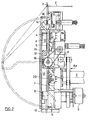
Fig. 1 zeigt eine Vorderansicht des Zuführteils einer Reissfestigkeitsprüfanlage, wie sie in der EP-A-403 988 beschrieben ist. Der zu prüfende Faden F wird dem Zuführteil von oben zugeführt, durchlauft diesen von oben nach unten und gelangt anschliessend in die nicht dargestellte Einlaufpartie des eigentlichen Prüfteils der Prüfanlage. Bezüglich des Prüfteils wird auf die EP-A-403 988 verwiesen.Fig. 1 shows a front view of the feed part of a tear strength testing system, as described in EP-A-403 988. The thread F to be tested is fed to the feed part from above, passes through it from top to bottom and then arrives in the inlet section (not shown) of the actual test part of the test system. Regarding the test part, reference is made to EP-A-403 988.
Darstellungsgemäss ist an der oberen Kante des Zuführteils ein Garnwechsler 1 angeordnet, der aus nebeneinander angeordneten Fadenführungsösen 2 und Garnklemmen 3 besteht. Diese bilden eine in Richtung des Pfeiles A schrittweise verschiebbare Klemmleiste mit beispielsweise je 12 Fadenführungsösen 2 und Garnklemmen 3. Auf einem Spulenspeicher der beispielsweise in der CH-Patentanmeldung Nr. 2072/90 beschriebenen Art werden die zu prüfenden Spulen aufgesteckt und die Fäden werden von Hand in die Führungsösen 2 und Garnklemmen 3 eingelegt und sind zwischen diesen gespannt. Wie insbesondere Fig. 2 entnommen werden kann, können die eingespannten Fäden an ihrem freien Stück zwischen Fadenführungsöse 2 und Garnklemme 3 von einem geeigneten Einlegeorgan ergriffen und durch die Fadenführungsösen 2 abgezogen werden.As shown, a yarn changer 1 is arranged on the upper edge of the feed part, which consists of
Nach dem Garnwechsler 1 ist in Fadenlaufrichtung eine Schere 4 angeordnet, nach dieser ein Changierorgan 5 und anschliessend an dieses ein Paar motorisch antreibbarer Lieferwalzen 6, mit denen der Faden F im Prüfbetrieb kontinuierlich von seinem Vorrat abgezogen wird. Das Changierorgan 5 ist senkrecht zur Zeichenebene hin- und hergehend angetrieben und führt dabei den Faden F zwischen den Lieferwalzen 6 vorwärts und rückwärts, was eine gleichmässige Beanspruchung der Lieferwalzen 6 und damit einen einwandfreien Fadenabzug gewährleistet.After the yarn changer 1 a pair of
Da die im Prüfteil der Reissfestigkeitsprüfanlage erfolgenden Schritte Klemmen, Dehnen, Reissen und Freigabe des Fadens diskontinuierlich ablaufen, der Faden F aber durch die Lieferwalzen 6 kontinuierlich abgezogen wird, ist zwischen den Lieferwalzen 6 und dem Prüfteil ein Fadenspeicher vorgesehen. Dieser umfasst einen pneumatischen Fadenspeicher 7, wie er beispielsweise von Luftdüsenwebmaschinen her bekannt ist, und eine gesteuerte Fadenklemme 8, die aus einer kontinuierlich angetriebenen Steuerwalze mit abgestuftem Umfang und aus einer frei drehbaren Gegenwalze besteht. Die gesteuerte Fadenklemme 8 ermöglicht eine gesteuerte Leerung des Fadenspeichers 7, wobei wegen des abgestuften Umfangs der Steuerwalze der Faden F durch die Fadenklemme 8 entweder geklemmt oder freigegeben ist.Since the steps of clamping, stretching, tearing and releasing the thread take place discontinuously in the test part of the tear resistance test system, but the thread F is continuously drawn off by the
Der Antrieb der Steuerwalze ist über einen Riemenantrieb RA mit demjenigen der Lieferwalzen 6 gekoppelt. Mit dem Bezugszeichen 9 ist ein Inkrementalgeber für die Steuerwalze der Fadenklemme 8 bezeichnet. Wie Fig. 2 weiter zu entnehmen ist, sind die Organe Schere 4, Changierorgan 5, Lieferwalzen 6, Fadenspeicher 7 und gesteuerte Fadenklemme 8 in einem flachen Gehäuse angeordnet, das durch eine ausgefräste Abstufung 10 eine Platte 11 gebildet und nach vorne durch eine transparente Schwenktüre 12 abgeschlossen ist. Der Fadenspeicher 7 erstreckt sich vom Boden dieser Abstufung nach hinten und die anderen genannten Organe übertragen den Boden und reichen bis knapp an die Schwenktüre 12. In die in den Fig. 1 und 2 untere Seitenwand der Abstufung 10 ist eine Saugdüse 13 eingesetzt deren Längsachse mit dem Faden F fluchtet, und die zur Förderung des Fadens F aus dem Fadenspeicher 7 in einen Fadenführungskanal des Prüfteils der Prüfanlage dient.The drive of the control roller is coupled to that of the
Zu Beginn einer Prüfung wird der betreffende Faden F in den Zuführteil eingelegt und dabei bis an die Düse 13 gebracht, von der er dann pneumatisch in den Prüfteil gefördert wird. Das Einlegen erfolgt durch einen Mechanismus, der im wesentlichen aus zwei Komponenten besteht, aus dem schon beschriebenen Garnwechsler 1 und aus einem Einlegearm 14. Der letztere ist nadelförmig ausgebildet und hat eine annähernd L-förmige Gestalt mit einem längeren und einem von diesem abgesetzten kürzeren Schenkel. Der längere Schenkel ist auf einem in einem Lagerbock 15 gelagerten scheiben- oder klotzartigen Träger 16 befestigt, der über einen Zahnriemen 17 (Fig. 2) motorisch antreibbar ist. Der kürzere Schenkel trägt an seinem freien Ende einen Finger 18, an dem ein Fadenführer 19 befestigt ist. Der längere Schenkel erstreckt sich in Fadenlaufrichtung, der kürzere Schenkel quer zu dieser.At the start of a test, the thread F in question is inserted into the feed part and brought up to the
Die Fig. 1 und 2 zeigen den Einlegearm 14 in jeweils zwei Stellungen, und zwar in der Ruhestellung und in der Arbeitsstellung, die einen Winkelabstand von 180° aufweisen, und zwischen denen der Einlegearm 14 durch seinen Antrieb verschwenkbar ist. In Fig. 1 ist die Ruhestellung und in Fig. 2 die Arbeitsstellung mit vollen Linien eingezeichnet. In beiden Stellungen liegt der Fadenführer 19 etwa im Niveau des Bodens der Abstufung 10 und somit hinter dem Faden F. In der Arbeitsstellung ragt der Einlegearm 14 oben aus der Abstufung 10 heraus und der Fadenführer 19 ist im Garnwechsler 1 zwischen der Fadenführungsöse 2 und der Garnklemme 3 positioniert. In der Ruhestellung liegt der Fadenführer 19 knapp oberhalb der Saugdüse 13. Eine in den Boden der Abstufung 10 eingefräste, den Einlegearm 14 umgebende Nut 20 mit abgestufter Tiefe ermöglicht das Verschwenken des Einlegearms 14 bis in das Niveau des genannten Bodens. Im Bereich des an den Träger 16 anschliessenden Teils des längeren Schenkels des Einlegearms 14 ist im Boden der Nut 20 zu beiden Seiten des Trägers 16 je ein diesen Boden überragender Mikroschalter 21, 22 angeordnet, durch dessen Betätigung der über den Zahnriemen 17 den Träger 16 antreibende Motor gestoppt und ein das Erreichen der Arbeits- bzw. Ruhestellung des Einlegearms 14 anzeigendes Signal erzeugt wird.1 and 2 show the
Bei dem in Fig. 1 dargestellten Funktionszustand ist die Anlage zur Prüfung einer Reihe von Fäden F vorbereitet; die Fäden wurden von Hand in den Garnwechsler 1 eingelegt und der Einlegearm 14 befindet sich in seiner Ruhestellung, in der er seit der letzten Einlegeoperation verharrt. Die Lieferwalzen 6 sind etwas auseinandergeschwenkt, so dass zwischen ihnen ein Spalt gebildet ist, und die gesteuerte Fadenklemme 8 ist offen. Mit dem Drücken des Startknopfes wird einerseits die Saugdüse 13 aktiviert, und andererseits schwenkt der Einlegearm 14 in seine Arbeitsposition (Fig. 2), deren Erreichen durch den Mikroschalter 21 signalisiert wird. Nun wird der Garnwechsler 1 um einen Schritt in Richtung des Pfeiles A nach rechts verschoben, wodurch der Faden F der vordersten, aus Fadenführungsöse 2 und Garnklemme 3 gebildeten, Zelle des Garnwechslers 1 dem Fadenführer 19 vorgelegt wird. Die Länge des Arbeitsschritts des Garnwechslers 1 entspricht dem halben gegenseitigen Abstand der in diesem eingespannten Fäden. Ist die Vorlegeposition erreicht, was anhand der Verschiebung des Garnwechslers 1 detektiert wird, wird der Antriebsmotor des Trägers 16 eingeschaltet, wodurch der Einlegearm 14 aus seiner Arbeits- in die Ruhestellung geschwenkt wird. Dabei beschreibt der Fadenführer 19 den in Fig. 2 strichpunktiert eingezeichneten Halbkreis und erfasst unmittelbar nach Verlassen der Arbeitsstellung den ihm vorgelegten Faden F. Da dieser Faden in der Garnklemme 3 fixiert ist, wird er bei der Schwenkbewegung des Einlegearms 14 als Schlaufe aus der Fadenführungsöse 2 herausgezogen, wobei sein zwischen Garnklemme 3 und dem Fadenführer 19 gespanntes Teilstück wie ein Zeiger gegen die Verbindungsachse zwischen dem Spalt zwischen den Lieferwalzen 6 und dem offenen Klemmspalt der gesteuerten Fadenklemme 8 bewegt wird.In the functional state shown in FIG. 1, the system is prepared for testing a series of threads F; the threads were inserted by hand into the yarn changer 1 and the
Nach Erreichen von etwa 170° des 180° Schwenkwinkels wird das genannte Teilstück des Fadens F zuerst in die gesteuerte Fadenklemme 8 und dann zwischen die Lieferwalzen 6 eingelegt bis schliesslich der Fadenführer 19 die Eintrittsöffnung der Saugdüse 13 überstreicht und der Faden F dem Sog der Düse ausgesetzt wird. Unmittelbar darauf erreicht der Einlegearm 14 seine Ruhestellung, was durch den Mikroschalter 22 signalisiert wird. Dadurch wird einerseits die Garnklemme 3 geöffnet und andererseits werden die Lieferwalzen 6 gestartet und gegeneinander geschwenkt und der Faden F wird nun durch die letzteren von seinem Vorrat abgezogen und durch die Saugdüse 13 der Prüfstrecke zugeführt. Gleichzeitig wird der Fadenspeicher 7 aktiviert.After reaching about 170 ° of the 180 ° swivel angle, said section of the thread F is first placed in the controlled
Nach Abschluss der Prüfung, deren Dauer beispielsweise an einem Teil der Prüfanlage bildenden Bedienungsgerät eingestellt oder von diesem automatisch gesteuert wird, wird die Garnklemme 3 geschlossen und der Garnwechsler 1 um einen Arbeitsschritt in Richtung des Pfeiles A verschoben. Gleichzeitig werden die Lieferwalzen 6 voneinander weggeschwenkt und angehalten. Ebenso wird der Antrieb der gesteuerten Fadenklemme 8 gestoppt, und zwar so, dass die Klemme geöffnet ist, und der Fadenspeicher 7 wird ebenfalls abgeschaltet. Der Faden F liegt nun im Wirkungsbereich der Schere 4 und wird von dieser abgeschnitten. Das abgeschnittene Fadenende wird von der Düse 13 abgesaugt. Damit ist die Anlage für eine weitere Prüfung bereit, die mit dem Zurückschwenken des Einlegearms 14 in die Arbeitsstellung beginnt.After completion of the test, the duration of which is set, for example, on an operating device forming part of the test system or is automatically controlled by the latter, the yarn clamp 3 is closed and the yarn changer 1 is shifted by one work step in the direction of arrow A. At the same time, the
Selbstverständlich wird jeweils vor dem Zurückschwenken des Einlegearms 14 in die Arbeitsstellung die Schwenktüre 12 geöffnet; diese bleibt solange offen, bis der Einlegearm 14 wieder seine Ruhestellung erreicht hat und wird dann automatisch geschlossen. Das Oeffnen der Tür 12 wird durch die Betätigung des Startknopfs ausgelöst, das Schliessen durch den Mikroschalter 22.Of course, the
Claims (12)
Applications Claiming Priority (4)
| Application Number | Priority Date | Filing Date | Title |
|---|---|---|---|
| CH2187/92 | 1992-07-10 | ||
| CH218792A CH685649A5 (en) | 1992-07-10 | 1992-07-10 | Yarn testing instrument |
| CH218792 | 1992-07-10 | ||
| US08/090,009 US5351535A (en) | 1992-07-10 | 1993-07-12 | Mechanism for inserting a thread into a yarn tester |
Publications (3)
| Publication Number | Publication Date |
|---|---|
| EP0585555A2 true EP0585555A2 (en) | 1994-03-09 |
| EP0585555A3 EP0585555A3 (en) | 1994-11-23 |
| EP0585555B1 EP0585555B1 (en) | 1999-10-06 |
Family
ID=25689750
Family Applications (1)
| Application Number | Title | Priority Date | Filing Date |
|---|---|---|---|
| EP93110581A Expired - Lifetime EP0585555B1 (en) | 1992-07-10 | 1993-07-02 | Mechanism for inserting a yarn in a yarn tester |
Country Status (4)
| Country | Link |
|---|---|
| US (1) | US5351535A (en) |
| EP (1) | EP0585555B1 (en) |
| JP (1) | JP3263748B2 (en) |
| CN (1) | CN1038066C (en) |
Cited By (3)
| Publication number | Priority date | Publication date | Assignee | Title |
|---|---|---|---|---|
| CN103822779A (en) * | 2014-02-22 | 2014-05-28 | 咸阳经纬纺织机械有限公司 | Testing system for comprehensive quality of main spraying nozzle of air-jet loom and testing method |
| WO2016149841A1 (en) * | 2015-03-20 | 2016-09-29 | Uster Technologies Ag | Yarn-checking device having a yarn insertion device |
| WO2016149845A1 (en) * | 2015-03-20 | 2016-09-29 | Uster Technologies Ag | Semiautomatic thread-changing device for a thread-testing device |
Families Citing this family (5)
| Publication number | Priority date | Publication date | Assignee | Title |
|---|---|---|---|---|
| WO2002038843A2 (en) * | 2000-11-09 | 2002-05-16 | Barmag Ag | Texturing machine and method for spreading a running thread |
| DE102009030880A1 (en) | 2009-06-29 | 2010-12-30 | Oerlikon Textile Gmbh & Co. Kg | Thread treatment device for thermal-mechanical treatment of continuously tapered melt-spinning threads, has guide defining travel path, which is alternately left- and right-sidedly bent according to position of aggregates |
| EP3161478B1 (en) * | 2015-03-20 | 2018-06-20 | Uster Technologies AG | Modular thread testing device |
| ITUB20155052A1 (en) | 2015-10-20 | 2017-04-20 | Mesdan Spa | MODULAR EQUIPMENT FOR THE AUTOMATIC DETERMINATION OF CHARACTERISTICS OF EXTENDED TEXTILE SAMPLES OF THE TYPE OF YARNS, WIRES, TAPES AND THE LIKE. |
| ITUB20154807A1 (en) * | 2015-10-20 | 2017-04-20 | Mesdan Spa | MEASUREMENT DEVICE FOR THE MEASUREMENT OF DYNAMOMETRIC CHARACTERISTICS OF TEXTILE SAMPLES EXTENDED IN THE TYPE OF YARNS, WIRES, TAPES AND THE LIKE. |
Citations (4)
| Publication number | Priority date | Publication date | Assignee | Title |
|---|---|---|---|---|
| AT181101B (en) * | 1950-04-14 | 1955-02-25 | Zellweger Uster Ag | Device for feeding individual lengths of threads u. Like. On thread testing machines |
| DE1905161A1 (en) * | 1968-02-05 | 1969-08-28 | Leesona Corp | Device for guiding a thread of yarn |
| DE3012499A1 (en) * | 1979-09-19 | 1981-04-02 | Zellweger Uster AG, 8610 Uster | DEVICE FOR INSERTING A THREAD IN THE TEST RANGE OF TENSILE STRENGTH Testers |
| EP0403988A2 (en) * | 1989-06-20 | 1990-12-27 | Zellweger Luwa Ag | Device for determining strength characteristics of elongated textile material samples |
Family Cites Families (10)
| Publication number | Priority date | Publication date | Assignee | Title |
|---|---|---|---|---|
| US1358793A (en) * | 1917-10-02 | 1920-11-16 | United Sroe Machinery Corp | Feeding device |
| DE824861C (en) * | 1950-04-14 | 1951-12-13 | Zellweger A G App Und Maschine | Device for feeding and checking individual lengths of threads u. Like. In thread testing machines |
| GB1306808A (en) * | 1969-12-22 | 1973-02-14 | Turner Brothers Asbest | Methods of and apparatus for conveying thread |
| US3741050A (en) * | 1970-05-27 | 1973-06-26 | Ici Ltd | Method of stringing a thread through a hole |
| US3805607A (en) * | 1971-08-27 | 1974-04-23 | Zellweger Uster Ag | Yarn changing mechanism |
| US3751981A (en) * | 1971-11-15 | 1973-08-14 | Celanese Corp | Yarn measuring and yarn feeding therefor |
| US3822539A (en) * | 1972-10-24 | 1974-07-09 | Ici Ltd | Threadable yarn treatment tube |
| US4169551A (en) * | 1978-02-28 | 1979-10-02 | Ppg Industries, Inc. | Apparatus for threading moving strands |
| GB2130157B (en) * | 1982-11-09 | 1986-02-19 | Latchways Ltd | Threading device |
| US5203206A (en) * | 1989-01-04 | 1993-04-20 | Zellweger Uster, Inc. | Apparatus and methods for testing tension-elongation or cross-sectional properties of single fibers and multiple fiber bundles |
-
1993
- 1993-06-24 JP JP19505993A patent/JP3263748B2/en not_active Expired - Fee Related
- 1993-07-02 EP EP93110581A patent/EP0585555B1/en not_active Expired - Lifetime
- 1993-07-10 CN CN93108423A patent/CN1038066C/en not_active Expired - Fee Related
- 1993-07-12 US US08/090,009 patent/US5351535A/en not_active Expired - Lifetime
Patent Citations (4)
| Publication number | Priority date | Publication date | Assignee | Title |
|---|---|---|---|---|
| AT181101B (en) * | 1950-04-14 | 1955-02-25 | Zellweger Uster Ag | Device for feeding individual lengths of threads u. Like. On thread testing machines |
| DE1905161A1 (en) * | 1968-02-05 | 1969-08-28 | Leesona Corp | Device for guiding a thread of yarn |
| DE3012499A1 (en) * | 1979-09-19 | 1981-04-02 | Zellweger Uster AG, 8610 Uster | DEVICE FOR INSERTING A THREAD IN THE TEST RANGE OF TENSILE STRENGTH Testers |
| EP0403988A2 (en) * | 1989-06-20 | 1990-12-27 | Zellweger Luwa Ag | Device for determining strength characteristics of elongated textile material samples |
Cited By (3)
| Publication number | Priority date | Publication date | Assignee | Title |
|---|---|---|---|---|
| CN103822779A (en) * | 2014-02-22 | 2014-05-28 | 咸阳经纬纺织机械有限公司 | Testing system for comprehensive quality of main spraying nozzle of air-jet loom and testing method |
| WO2016149841A1 (en) * | 2015-03-20 | 2016-09-29 | Uster Technologies Ag | Yarn-checking device having a yarn insertion device |
| WO2016149845A1 (en) * | 2015-03-20 | 2016-09-29 | Uster Technologies Ag | Semiautomatic thread-changing device for a thread-testing device |
Also Published As
| Publication number | Publication date |
|---|---|
| EP0585555B1 (en) | 1999-10-06 |
| CN1038066C (en) | 1998-04-15 |
| JP3263748B2 (en) | 2002-03-11 |
| JPH0666697A (en) | 1994-03-11 |
| CN1087597A (en) | 1994-06-08 |
| EP0585555A3 (en) | 1994-11-23 |
| US5351535A (en) | 1994-10-04 |
Similar Documents
| Publication | Publication Date | Title |
|---|---|---|
| DE19722395C1 (en) | Double lock:stitch sewing machine thread cutter | |
| DE2332327C3 (en) | Device for feeding, separating and rinsing the beginning of the thread onto a running bobbin | |
| DE2939644C2 (en) | Method and device for eliminating an irregularity in the running thread at an open-end spinning station during spinning | |
| EP0054775B1 (en) | Device for sorting conical bobbins | |
| DE1585392C3 (en) | Device for delivering weft threads to a warp knitting machine | |
| DE2810741A1 (en) | Automatic splicer for broken ends on winding frame - transfers threads from above and below into pneumatic chamber | |
| DE2922694A1 (en) | METHOD AND DEVICE FOR CONNECTING AN UPPER THREAD TO A LOWER THREAD | |
| EP0585555B1 (en) | Mechanism for inserting a yarn in a yarn tester | |
| EP0129043A2 (en) | Device and process for quilting | |
| EP0453543B1 (en) | Automatic socks turning device for a looping machine | |
| DE3305479A1 (en) | METHOD AND DEVICE FOR PNEUMATIC SPLICING OF SPONNED THREADS | |
| DE2847520C3 (en) | Device for placing warp threads in front of them for automatic drawing in of the healds and lamellas of a weaving machine | |
| DE2856871A1 (en) | PROCESS AND DEVICE FOR THE MANUFACTURING OF CONTINUOUSLY EMBROIDERED FABRICS | |
| DE2737197C2 (en) | Jet loom | |
| DE3844043C2 (en) | ||
| CH685649A5 (en) | Yarn testing instrument | |
| DE3830772C2 (en) | ||
| DE2514794A1 (en) | Sewing mach for assembling two annular bands of different elasticity - includes support for advancing bands through stitching position | |
| DE2041043C3 (en) | Feed device for a yarn changing device used to hold a number of yarns to be tested | |
| DE3132894C2 (en) | ||
| CH681900A5 (en) | ||
| DE2815999C2 (en) | ||
| EP0333190A2 (en) | Device for selectively feeding one of more weft threads to a gripper shuttle | |
| DE1914397B2 (en) | ENTRY NEEDLE OF A WEAVING MACHINE | |
| DE3843399A1 (en) | AIR WOVENING MACHINE WITH A DEVICE FOR REMOVING A DEFECTIVE WIFE FROM THE WEAVING COMPARTMENT |
Legal Events
| Date | Code | Title | Description |
|---|---|---|---|
| PUAI | Public reference made under article 153(3) epc to a published international application that has entered the european phase |
Free format text: ORIGINAL CODE: 0009012 |
|
| AK | Designated contracting states |
Kind code of ref document: A2 Designated state(s): BE DE ES FR GB IT |
|
| RAP1 | Party data changed (applicant data changed or rights of an application transferred) |
Owner name: ZELLWEGER LUWA AG |
|
| PUAL | Search report despatched |
Free format text: ORIGINAL CODE: 0009013 |
|
| RHK1 | Main classification (correction) |
Ipc: G01N 3/04 |
|
| AK | Designated contracting states |
Kind code of ref document: A3 Designated state(s): BE DE ES FR GB IT |
|
| 17P | Request for examination filed |
Effective date: 19950518 |
|
| GRAG | Despatch of communication of intention to grant |
Free format text: ORIGINAL CODE: EPIDOS AGRA |
|
| 17Q | First examination report despatched |
Effective date: 19980821 |
|
| GRAG | Despatch of communication of intention to grant |
Free format text: ORIGINAL CODE: EPIDOS AGRA |
|
| GRAH | Despatch of communication of intention to grant a patent |
Free format text: ORIGINAL CODE: EPIDOS IGRA |
|
| GRAH | Despatch of communication of intention to grant a patent |
Free format text: ORIGINAL CODE: EPIDOS IGRA |
|
| GRAA | (expected) grant |
Free format text: ORIGINAL CODE: 0009210 |
|
| AK | Designated contracting states |
Kind code of ref document: B1 Designated state(s): BE DE ES FR GB IT |
|
| PG25 | Lapsed in a contracting state [announced via postgrant information from national office to epo] |
Ref country code: ES Free format text: THE PATENT HAS BEEN ANNULLED BY A DECISION OF A NATIONAL AUTHORITY Effective date: 19991006 |
|
| GBT | Gb: translation of ep patent filed (gb section 77(6)(a)/1977) |
Effective date: 19991006 |
|
| ITF | It: translation for a ep patent filed |
Owner name: FIAMMENGHI - DOMENIGHETTI |
|
| REF | Corresponds to: |
Ref document number: 59309816 Country of ref document: DE Date of ref document: 19991111 |
|
| ET | Fr: translation filed | ||
| PLBE | No opposition filed within time limit |
Free format text: ORIGINAL CODE: 0009261 |
|
| STAA | Information on the status of an ep patent application or granted ep patent |
Free format text: STATUS: NO OPPOSITION FILED WITHIN TIME LIMIT |
|
| 26N | No opposition filed | ||
| REG | Reference to a national code |
Ref country code: GB Ref legal event code: IF02 |
|
| PGFP | Annual fee paid to national office [announced via postgrant information from national office to epo] |
Ref country code: GB Payment date: 20020626 Year of fee payment: 10 |
|
| PG25 | Lapsed in a contracting state [announced via postgrant information from national office to epo] |
Ref country code: GB Free format text: LAPSE BECAUSE OF NON-PAYMENT OF DUE FEES Effective date: 20030702 |
|
| REG | Reference to a national code |
Ref country code: FR Ref legal event code: TP |
|
| GBPC | Gb: european patent ceased through non-payment of renewal fee |
Effective date: 20030702 |
|
| PGFP | Annual fee paid to national office [announced via postgrant information from national office to epo] |
Ref country code: FR Payment date: 20060719 Year of fee payment: 14 |
|
| PGFP | Annual fee paid to national office [announced via postgrant information from national office to epo] |
Ref country code: BE Payment date: 20060912 Year of fee payment: 14 |
|
| BERE | Be: lapsed |
Owner name: *USTER TECHNOLOGIES A.G. Effective date: 20070731 |
|
| REG | Reference to a national code |
Ref country code: FR Ref legal event code: ST Effective date: 20080331 |
|
| PG25 | Lapsed in a contracting state [announced via postgrant information from national office to epo] |
Ref country code: BE Free format text: LAPSE BECAUSE OF NON-PAYMENT OF DUE FEES Effective date: 20070731 |
|
| PG25 | Lapsed in a contracting state [announced via postgrant information from national office to epo] |
Ref country code: FR Free format text: LAPSE BECAUSE OF NON-PAYMENT OF DUE FEES Effective date: 20070731 |
|
| PGFP | Annual fee paid to national office [announced via postgrant information from national office to epo] |
Ref country code: DE Payment date: 20110629 Year of fee payment: 19 |
|
| PGFP | Annual fee paid to national office [announced via postgrant information from national office to epo] |
Ref country code: IT Payment date: 20110728 Year of fee payment: 19 |
|
| PG25 | Lapsed in a contracting state [announced via postgrant information from national office to epo] |
Ref country code: DE Free format text: LAPSE BECAUSE OF NON-PAYMENT OF DUE FEES Effective date: 20130201 |
|
| PG25 | Lapsed in a contracting state [announced via postgrant information from national office to epo] |
Ref country code: IT Free format text: LAPSE BECAUSE OF NON-PAYMENT OF DUE FEES Effective date: 20120702 |
|
| REG | Reference to a national code |
Ref country code: DE Ref legal event code: R119 Ref document number: 59309816 Country of ref document: DE Effective date: 20130201 |