EP0585092A1 - Automatische Wickelmaschine für bandartige Produkte - Google Patents
Automatische Wickelmaschine für bandartige Produkte Download PDFInfo
- Publication number
- EP0585092A1 EP0585092A1 EP93306651A EP93306651A EP0585092A1 EP 0585092 A1 EP0585092 A1 EP 0585092A1 EP 93306651 A EP93306651 A EP 93306651A EP 93306651 A EP93306651 A EP 93306651A EP 0585092 A1 EP0585092 A1 EP 0585092A1
- Authority
- EP
- European Patent Office
- Prior art keywords
- tape
- article
- winding
- unit
- spool
- Prior art date
- Legal status (The legal status is an assumption and is not a legal conclusion. Google has not performed a legal analysis and makes no representation as to the accuracy of the status listed.)
- Granted
Links
Images


Classifications
-
- A—HUMAN NECESSITIES
- A44—HABERDASHERY; JEWELLERY
- A44B—BUTTONS, PINS, BUCKLES, SLIDE FASTENERS, OR THE LIKE
- A44B18/00—Fasteners of the touch-and-close type; Making such fasteners
- A44B18/0069—Details
-
- B—PERFORMING OPERATIONS; TRANSPORTING
- B65—CONVEYING; PACKING; STORING; HANDLING THIN OR FILAMENTARY MATERIAL
- B65H—HANDLING THIN OR FILAMENTARY MATERIAL, e.g. SHEETS, WEBS, CABLES
- B65H19/00—Changing the web roll
- B65H19/22—Changing the web roll in winding mechanisms or in connection with winding operations
- B65H19/26—Cutting-off the web running to the wound web roll
-
- B—PERFORMING OPERATIONS; TRANSPORTING
- B65—CONVEYING; PACKING; STORING; HANDLING THIN OR FILAMENTARY MATERIAL
- B65H—HANDLING THIN OR FILAMENTARY MATERIAL, e.g. SHEETS, WEBS, CABLES
- B65H19/00—Changing the web roll
- B65H19/22—Changing the web roll in winding mechanisms or in connection with winding operations
- B65H19/28—Attaching the leading end of the web to the replacement web-roll core or spindle
- B65H19/286—Attaching the leading end of the web to the replacement web-roll core or spindle by applying adhesive to the web
-
- B—PERFORMING OPERATIONS; TRANSPORTING
- B65—CONVEYING; PACKING; STORING; HANDLING THIN OR FILAMENTARY MATERIAL
- B65H—HANDLING THIN OR FILAMENTARY MATERIAL, e.g. SHEETS, WEBS, CABLES
- B65H19/00—Changing the web roll
- B65H19/22—Changing the web roll in winding mechanisms or in connection with winding operations
- B65H19/29—Securing the trailing end of the wound web to the web roll
-
- B—PERFORMING OPERATIONS; TRANSPORTING
- B65—CONVEYING; PACKING; STORING; HANDLING THIN OR FILAMENTARY MATERIAL
- B65H—HANDLING THIN OR FILAMENTARY MATERIAL, e.g. SHEETS, WEBS, CABLES
- B65H19/00—Changing the web roll
- B65H19/22—Changing the web roll in winding mechanisms or in connection with winding operations
- B65H19/30—Lifting, transporting, or removing the web roll; Inserting core
- B65H19/305—Inserting core
-
- B—PERFORMING OPERATIONS; TRANSPORTING
- B65—CONVEYING; PACKING; STORING; HANDLING THIN OR FILAMENTARY MATERIAL
- B65H—HANDLING THIN OR FILAMENTARY MATERIAL, e.g. SHEETS, WEBS, CABLES
- B65H35/00—Delivering articles from cutting or line-perforating machines; Article or web delivery apparatus incorporating cutting or line-perforating devices, e.g. adhesive tape dispensers
- B65H35/0006—Article or web delivery apparatus incorporating cutting or line-perforating devices
- B65H35/0013—Article or web delivery apparatus incorporating cutting or line-perforating devices and applying the article or the web by adhesive to a surface
-
- B—PERFORMING OPERATIONS; TRANSPORTING
- B65—CONVEYING; PACKING; STORING; HANDLING THIN OR FILAMENTARY MATERIAL
- B65H—HANDLING THIN OR FILAMENTARY MATERIAL, e.g. SHEETS, WEBS, CABLES
- B65H2301/00—Handling processes for sheets or webs
- B65H2301/40—Type of handling process
- B65H2301/41—Winding, unwinding
- B65H2301/414—Winding
- B65H2301/41419—Starting winding process
- B65H2301/41427—Starting winding process involving arrangements for securing leading edge to core, e.g. adhesive tape
-
- B—PERFORMING OPERATIONS; TRANSPORTING
- B65—CONVEYING; PACKING; STORING; HANDLING THIN OR FILAMENTARY MATERIAL
- B65H—HANDLING THIN OR FILAMENTARY MATERIAL, e.g. SHEETS, WEBS, CABLES
- B65H2301/00—Handling processes for sheets or webs
- B65H2301/40—Type of handling process
- B65H2301/41—Winding, unwinding
- B65H2301/417—Handling or changing web rolls
- B65H2301/418—Changing web roll
- B65H2301/4181—Core or mandrel supply
- B65H2301/41814—Core or mandrel supply by container storing cores and feeding through wedge-shaped slot or elongated channel
Definitions
- This invention relates generally to a machine for automatically winding flexible tape-like articles, such as surface fasteners, slide fastener chains and ornamental tapes, and more particularly to an automatic winding machine for flexible tape-like articles, which is provided with a mechanism for efficiently securing a leading end of the tape-like article on a spool body.
- a spool includes a hollow cylinder body having an opening defined in the annular periphery wall of the spool body.
- the axial hole in the spool body is circumstanced to be under negative pressure to create a suction force acting around the cylinder body.
- the leading end of the tape-like article is sucked toward the opening and adhered to the annular wall of the spool body to wind the tape-like article on the spool body.
- the mechanical holding means includes a row of locking needles movably mounted in the hollow portion so as to selectively project outwardly beyond the annular wall through the opening of the spool body to be threaded through the leading end of the tape-like article at the start of winding the tape-like article around the spool body.
- the trough-like guide member is provided adjacent to and above the spool body in perpendicular relation to the axis of the spool body to introduce the leading end of the flexible tape-like article onto the spool body.
- the leading end of the flexible tape-like article guided by the guide member and fed continuously is hung from the tip end of the guide member toward the peripheral surface of the spool body and then is locked on the spool body by the suction force to wind automatically the flexible tape-like article on the spool thereafter.
- the tape-like article winding apparatus disclosed in the above Japanese Patent Publication, since the leading end of the tape-like article is held on the spool body without the time-consuming manual operation, the tape-like article may be efficiently wound on the spool having large flanges attached to both sides of the spool body to achieve the complete automation in the start of winding.
- the cost of the spools should be reduced as much as possible.
- the spool since the spool comprises a hollow cylindrical body having an elongate opening defined in its peripheral wall to assure the suction force of the hollow body or the projection and retraction of locking needles, the spool which is generally used and is inexpensive cannot be used due to the necessity of unique structure described above, so that the cost increases.
- the feed mechanism for feeding the flexible tape-like article to the winding spool in the automatic winding apparatus since the mechanism intends to guide the tape-like article through the trough-like guide members onto the peripheral surface of the winding spool, it is not assured to hold surely the leading end of the tape-like article on the peripheral surface of the spool.
- the tape-like articles produce ill-wound appearance and different wound lengths to reduce the commercial value when a plurality of tape-like articles are simultaneously wound. Therefore, the inspections for wound appearnace and wound lengths require the time and the labor to deteriorate its economy and productivity.
- a machine for automatically winding a flexible tape-like article comprising a double-sided adhesive tape sticking unit having a feed section for a double-sided adhesive tape, a severing section for severing the adhesive portion of the adhesive tape fed from the feed section into a predetermined length, and a rewinding section for intermittently rewinding a separated paper for a predetermined length, said adhesive tape sticking unit is for sticking the severed adhesive portion to a back surface of a leading end of the tape-like article fed from the feed section, a tape-like article winding unit having an automatic exchanging mechanism for winding spools, and a guide means for the tape-like article, said winding unit is for winding the tape-like article for a predetermined length on the winding spool, and n tape-like article drawing and winding unit having a tape end gripping means for gripping the leading end of the tape-like article on the back surface of which the double-sided adhesive tape is adhered by the
- the tape-like article feed section of the feed unit is composed of a feeding and severing portion for feeding and severing first and second tape-like articles for a predetermined length and a joining portion for joining the severed piece of the second tape-like article to a feeding end of the first tape-like article.
- guide members for guiding plural tape-like articles in parallel are disposed between the double-sided adhesive tape sticking unit and the winding spool of the tape-like article winding unit, and the tape-like article winding unit has an automatic empty spool supplying means.
- a feed gripper is actuated to project a second tape-like article for a predetermined length into a passage of a movable cutter.
- the movable cutter is moved upwardly to cut off the first tape-like article and then to cut off the projected end of the second tape-like article in co-operation with the stationary cutter.
- the projected end of the severed piece is joined onto the wound surface layer by a proper press means to be a finished product.
- the finished product is removed from the winding unit, the product is always kept from collapsing.
- a leading end of a new first tape-like article is fed from the tape-like article feed unit through a discharge guide for a predetermined length.
- a double-sided adhesive tape feed section is located far below a press roller.
- the double-sided adhesive tape feeding portion is lifted up to hold the leading end of the first tape-like article between the press roller and the double-sided adhesive tape sticking roller.
- the adhesive tape severing means is actuated to exert a cutting blade upon the surface of the adhesive tape guiding portion to cut off the adhesive tape while leaving the separated paper uncut.
- the cutting blade returns, and at the same time, the sticking roller is rotated at the predetermined angle to feed the first tape-like article outwardly and to adhere the severed piece of the double-sided adhesive tape onto the back surface of the first tape-like article so as to draw the tape-like article from the discharge guide for the predetermined length. Then, the separated paper rewinding roller is simultaneously driven to wind the separated paper on the rewinding roller. At this time, the gripper of the tape-like article drawing and winding unit is standing-by in front of the press roller and the sticking roller to grip the leading end of the first tape-like article.
- the rotation of the separated paper rewinding roller is stopped and the leading end of the tape-like article is fed into the gripper while being held between the press roller and the sticking roller.
- the double-sided adhesive tape feeding portion is lowered to release the holding. The leading end of the tape-like article is transferred by means of the gripper to the predetermined location of the tape-like article winding unit.
- the tape-like article drawing and winding unit provided with the gripper stands-by in the upwardly front location of the tape-like article winding unit in winding of the first tape-like article.
- the drawing and winding unit is moved horizontally to the tape-like article gripping location in front of the press roller and the sticking roller. After the leading end of the tape-like article is gripped by the gripper, the drawing and winding unit is returned to the original location and is moreover displaced downwardly therefrom.
- one of tape-like article pressing portions is inclined downwardly and the press member pushes the leading end surface of the first tape-like article on the peripheral surface of the spool body to stick and join the double-sided adhesive tape adhered to the back surface of the leading end onto the peripheral surface of the spool body.
- the tape-like article drawing and winding unit is returned to the stand-by location and the actuation of the winding unit is started to commence the winding of the first tape-like article.
- the movable cutter of the tape-like article feed unit is lifted up to cut off the first tape-like article and then to cut off the projected end of the second tape-like article in co-operation with the stationary cutter.
- the severed piece of the second tape-like article is adhered to the severed end of the first tape-like article, the end of the first tape-like article is attached and secured to the surface layer via the projected end of the severed piece to finish the winding.
- the above-mentioned operation is repeated to wind automatically the tape-like article on the winding spool for the predetermined length and to join the end to the wound surface.
- An automatic winding apparatus of this invention comprises a flexible tape-like article feed unit 1, a double-sided adhesive tape sticking unit 2, a flexible tape-like article drawing and winding unit 3, and a flexible tape-like article winding unit 4, as shown in FIG. 1.
- a known feed unit disclosed for example in Japanese Patent Publication No. H 1-15283 is adapted in the tape-like article feed unit 1 of this automatic winding machine. That is, the tape-like article feed unit 1 is provided with a severing and joining means for severing a joint piece from a second tape-like article Ta of a surface fastener to a predetermined length and attaching such a joint piece to a desired length on a first tape-like article Tb of a mating surface fastener.
- a pair of upper and lower feed rollers 11 and a feed guide 12 are horizontally arranged and a feed gripper 13 for the second tape-like article Ta is disposed above the feed rollers and the feed guide.
- a pair of upper and lower auxiliary rollers 15 and a discharge guide 14 are also arranged at the desired interval from the feed guide 12 in the discharge side of the first tape-like article Tb.
- the discharge guide 14 is extended for a predetermined length in front of the auxiliary rollers 15 and a first tape-like article discharging roller 14a is provided on the tip end of the discharge guide 14.
- the feed rollers 11 and the discharge roller 14a are associated with a stepping motor not shown in the drawing to carry out the stopping and feeding the first tape-like article Tb for every predetermined length.
- a stationary cutter 16 and a movable cutter 17 are disposed between the feed guide 12 and the discharge guide 14.
- the stationary cutter 16 has a first guide path 16a for horizontally feeding the first tape-like article Tb and an inclined second guide path 16b for feeding the second tape-like article Ta in a downwardly inclined direction.
- the movable cutter 17 is vertically moved and slid along the front surface of the stationary cutter 16 by a proper drive means.
- a downwardly inclined passage 17a is formed in the central portion of the movable cutter 17 to pass the first and second tape-like articles Tb and Ta.
- the feed side edge of a lower wall surface of the passage 17a is formed as a cutter blade and the upper wall surface thereof is formed as a guide surface for the second tape-like article Ta which is supplied in the downwardly inclined direction.
- the feeding is stopped, and at the same time, the feed gripper 13 is actuated to project the second tape-like article Ta for the predetermined length through the second guide path 16b into the passage 17a of the movable cutter 17.
- the movable cutter 17 is lifted up to cut off the first tape-like article Tb and then to cut off the projected portion of the second tape-like article Ta into a joint piece in co-operation with the stationary cutter 16.
- the projected end of the joint piece is attached and secured onto the surface of the wound surface layer to provide a finished product which can be prevented from being loosened off the reel after it has been removed from the winding unit 4.
- the tape-like article feed unit 1 is shown as the illustrative example and is not limited to the one described above, but various types of feed units having the same function may be also adapted, and various modification of the feed unit of this invention may be used as disclosed in the above-mentioned Publication.
- the first and second tape-like articles are described as the surface fasteners, but the first tape-like article Tb may be a slide fastener, a narrow film, an ornamental tape or the like and the second tape-like article Ta may be a pressure-sensitive adhesive tape or the like.
- a sticking unit 2 for sticking a double-sided adhesive tape of a predetermined length is located on the tape-like article discharge side of the feed unit 1.
- This double-sided adhesive tape sticking unit 2 is composed of a double-sided adhesive tape feeding and sticking means 21 for sticking the double-sided adhesive tape 5 of the predetermined length to the back surface of the leading end portion of the first tape-like article Tb fed from the discharge guide 14 of the feed unit 1, and an adhesive tape severing means 26 for severing only the adhesive portion of the adhesive tape 5 to the predetermined length.
- the double-sided adhesive tape feeding and sticking means 21 includes an upper stationary press roller section 22 and a vertically movable double-sided adhesive tape feeding section 23 which is disposed below the stationary press roller section 22, as shown in FIG. 1.
- the stationay press roller section 22 has a press roller 22a which is disposed to contact with the upper surface of the tape-like article fed from the discharge guide 14 of the feed unit 1.
- the double-sided adhesive tape feeding section 23 is composed of a block 24 which is vertically movable toward the press roller 22a by a cylinder not shown in the drawing.
- the block 24 has a reel 24a with the double-sided adhesive tape 5 wound around it, a plurality of rollers 24b - 24e for guiding the double-sided adhesive tape 5 and rewinding only the separated paper 5a, and a double-sided adhesive tape sticking roller 24f which is disposed opposite to the press roller 22a.
- the unwinding reel 24a for the double-sided adhesive tape 5 is rotatably supported in the lower central portion of the block 24.
- the adhesive tape 5 wound on the reel 24a is passed through the tension roller 24b to the peripheral surface of the adhesive tape sticking roller 24f. Only the separated paper 5a is turned downwardly and guided to the guide roller 24c and is further passed through a pair of right and left drawing rollers 24d and taken up on the rewinding roller 24e supported in the lower end of the block 24.
- a guide block 25 for slidably guiding the double-sided adhesive tape 5 having the separated paper is disposed in the upper part of the running path of the double-sided adhesive tape 5 between the tension roller 24b and the double-sided adhesive tape sticking roller 24f.
- the adhesive tape severing means 26 is fixed below the discharge guide 14 of the feed unit 1.
- a severing portion 27 is disposed in the upper end of a L-shaped lever 26a which is turnably supported pivotally at the central portion thereof.
- a cutting blade 27a is protruded from the severing portion 27 toward the adhesive tape feeding and sticking means 21.
- the other end of the L-shaped lever 26a is supported by the tip end of the piston rod of the cylinder 26b. Accordingly, when the cylinder 26b is actuated, the L-shaped lever 26a is turned about the central position thereof and the cutting blade 27a of the severing portion 27 is advanced and returned in the right and left directions of the drawing.
- the double-sided adhesive tape feeding section 23 is lifted up and the severing portion 27 is turned in the right direction, the blade edge of the cutting blade 27a is postioned to contact with the surface of the guide block 25.
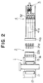
- the adhesive tape feeding section 23 is positioned below the press roller 22a as shown in FIG. 3 before the leading end of the first tape-like article Tb is fed from the discharge guide 14 of the feed unit 1.
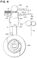
- the double-sided adhesive tape feeding section 23 is lifted up as shown in FIG. 4 to hold the leading end of the first tape-like article Tb between the press roller 22a and the double-sided adhesive tape sticking roller 24f.
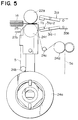
- the adhesive tape severing means 26 is actuated to apply the blade edge 27a to the double-sided adhesive tape 5 having the separated paper 5a so as to sever the adhesive tape 5 while leaving the separated paper 5a uncut, as shown in FIG. 5.
- the cutting blade 27a is returned and the double-sided adhesive tape sticking roller 24f is rotated by the predetermined rotation angle to feed out the first tape-like article Tb and the severed portion 5b of the double-sided adhesive tape 5 is stuck to the back surface of the first tape-like article Tb as shown in FIG. 6.
- the rewinding roller 24e is driven to start the rotation of the drawing roller 24d and to rewind the separated paper 5a on the rewinding roller 24e.
- the severed portion 5b of the double-sided adhesive tape 5 is drawn-out together with the first tape-like article Tb and stuck onto the back surface of the first tape-like article Tb. Then, a gripper 31a of the tape-like article drawing and winding unit 3 is standing-by in front of the both rollers 22a, 24f to hold the leading end of the first tape-like article Tb.
- the tape-like article drawing and winding unit 3 having the gripper 31 is standing-by in the upwardly front location of the tape-like article winding unit 4 as shown in FIG. 1 during winding of the first tape-like article Tb.
- the tape-like article drawing and winding unit 3 is horizontally moved to a position for gripping the tape-like article between the press roller 22a and the double-sided adhesive tape sticking roller 24f. After the leading end of the first tape-like article Tb is held by the gripper 31a, it is returned to its original location and is downwardly moved therefrom.
- the tape-like article drawing and winding unit 3 is provided with the tape-like article holding portion 31 and the tape-like article pressing portion 32 and can be horizontally and vertically moved by the cylinder means.
- FIG. 8 and FIG. 9 the tape-like article holding portion 31 and the tape-like article pressing portion 32 are shown in detail and are supported by a common support member 33.
- the support member 33 comprises an inversely L-shaped frame 34 and a bracket 35 projected horizontally from the lower end of the frame as shown in FIG. 1.
- the upper end horizontal portion of the inversely L-shaped frame 34 is attached to a vertical cylinder 36 secured to a machine base not shown, and the tape-like article holding portion 31 and the tape-like article press portion 32 are moved vertically by the vertical cylinder 36.
- a horizontal cylinder is also attached to the inversely L-shaped frame 34, and the tape-like article holding portion 31 and the tape-like article pressing portion 32 are also moved horizontally via the inversely L-shaped frame 34 by the horizontal cylinder.
- the bracket 35 is composed of upper and lower two separate steps structure as shown in FIG. 9.
- the tip end of the upper surface of the bracket 35 is formed as a downwardly inclined surface and a slide groove 35a-1 is extended in the protruding direction along the whole length of the bracket 35.
- a guide plate member 35a-2 is parallelly disposed with a predetermined interval to the bracket 35a.
- a cylinder support plate 35a-3 is attached to the right end of the guide plate member 35a-2 by bolts, and a push pin 35a-4 is resiliently protruded toward the slide groove 35a-1 and is mounted in the end of the guide plate member 35a-2.
- a sliding member 37 is engaged in the slide groove 35a-1 and the right portion of the sliding member 37 is engaged with the tip end of the piston rod of a cylinder 37a supported by the cylinder support plate 35a-3, so that the sliding member 37 is reciprocated by the actuation of the cylinder 37a.
- the tape-like article pressing portion 32 is vertically rotatably connected through a pin to the left end of the sliding member 37.
- the tape-like article press portion 32 comprises a base member 32a, arm members 32b, and press members 32c as shown in FIG. 8 and FIG. 9. According to this embodiment, since four first tape-like articles Tb are simultaneously wound, four sets of arm members 32b and press members 32c are also slidably accommodated in cavities 32a-1 which are parallelly formed in the base member. 32a.
- the individual arm member 32b is accommodated via a compression spring 32b-1 in the individual cavity 32a-1.
- a pair of rollers 32c-1 is provided in the end surface of the press member 32c to be contacted and pressed on the periphery of the winding spool 6.
- the base of the press member 32c is vertically turnably connected via a pin to the end of the arm member 32b.
- the tape-like article pressing portion 32 is downwardly pressed by the push pin 35a-4, so that the whole pressing portion is downwadly inclined along the downwardly slanted surface of the bracket 35a as shown in the phantom line.
- the rollers 32c-1 of the press member 32c are pressed against the peripheral surface of the winding spool 6 as shown by the phantom line.
- a lower bracket 35b has a wedge portion 35b-1 therein which is advanced and returned, and a pair of legs 35b-2 which are extended in parallel (in the vertical direction in FIG. 9) from the end thereof.
- the tape-like article holding portion 31 which is a part of the characterizing part of this invention, is held between a pair of the legs 35b-2. That is, a gripper 31a comprising a pair of upper and lower board holders 31a-1 is turnably supported between the legs 35b-2 by the pins 35a-3.
- the gripper 31 is opened by a coil spring 35b-4.
- the rear end of the holder 31a-1 is resiliently pushed on the surface of the wedge portion 35b-1.
- Mouthpieces 31a-2 are respectively welded to the opposed surfaces of the upper and lower holders 31a-1.
- the mouthpieces 31a-2 have the same width as the four first tape-like articles Tb to be able to grip simultaneously the four first tape-like articles Tb which are transferred in parallel.
- the fourth unit of this invention the tape-like article winding unit 4 is disposed ahead of the double-sided adhesive tape sticking unit 2 in the tape-like article feeding direction as shown in FIG. 1, and is composed of a known winding means not shown in the drawing, a tape-like article guiding portion 41 and an empty spool supplying means 42.
- the winding means is naturally provided with a spool exchanging mechanism.
- the tape-like article guiding portion 41 is composed of plural guide plates 41a which are arranged in parallel at intervals about equal to the width of the first tape-like article Tb fed from the feed unit 1.
- the lower tip ends of the guide plates 41a are disposed adjacent to the peripheral surface of the winding spool 6 on the winding means.
- a guide roller 41b is rotatably supported in the rear end (left side in the drawing) of the guide plate 41a. Since four first tape-like articles Tb are simultaneously wound, three guide plates 41a are disposed in parallell at the predetermined intervals and the guide roller 41b is attached to the rear end of the guide plates.
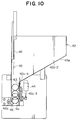
- the empty spool supplying means 42 is composed of an empty spool supplying hopper 42a disposed in front of the winding means and an automatic delivering member 42b arranged below the empty spool discharging opening of the hopper 42a, as shown in FIG. 1.
- FIG. 10 shows an enlarged sectional view of the empty spool supplying hopper 42a.
- the empty spool hopper 42a comprises a square inlet, a slanted surface 42a-2 inclined toward the opposite side wall 42a-1 and an empty spool discharging path 42a-3 which is extended vertically from the position where the interval between the lower end of the slanted surface 42a-2 and the opposite side wall 42a-1 is about equal to the ex ternal diameter of the empty spool 6a.
- a slit 42a-4 is formed in parallel to the longitudinal direction of the empty spool 6a in the lower end portion of the slanted surface 42a-2.
- a plate 43 is moved vertically to be projected through the slit 42a-4 into the hopper and is disposed along the external wall of the empty spool discharging path 42a-3.
- the vertically movable plate 43 is actuated by the cylinder 44.
- a vertically movable pushing plate 45 is also provided on the inner surface of the upper part of the opposite side wall 42a-1.
- a plurality of the empty spools 6a accommodated in the hopper are individually separated from the block of the empty spools when the vertically movable plate 43 is projected vertically into the hopper, and the empty spools 6a are aligned and individually discharged into the empty spool discharging path 42a-3 when the push plate 45 is lowered to push the empty spool.
- a lateral substantially V-shaped discharge-regulating member 46 is supported on a shaft 46a in the spool discharging opening of the lower end of the opposite side wall 42a-1 so that the discharge regulating member 46 can turn by the predetermined angle about the shaft parallel to the longitudinal direction of the empty spool 6a.
- the discharge regulating member 46 is driven at the predetermined timing by a turning and driving means not shown in the drawing and always set in the position shown by the solid line in FIG. 10.
- the discharge regulating member 46 returns to the original position to regulate the discharge of the succeeding empty spool 6a.
- the discharge regulating member 46 is turned between the solid line and the phantom line in FIG. 10 by a spring not shown.
- the automatic delivering member 42b is disposed below the empty spool discharging opening of the empty spool supplying hopper 42a and has an empty spool support 47 which is reciprocated between the empty spool discharging opening and the spool supporting portion of the winding means by the cylinder 42b-1 as shown in FIG. 1.
- This empty spool support 47 is composed of an arm having an upwardly opened substantially U-shaped section.
- the supporting portion 47a opposed to the winding means 4 usually stands upright by being urged by the spring 47b and is turned to the horizontal position when the load is applied from the inside to the supporting portion. Until the preceding winding is finished, the empty spool support 47 is located at the position shown in FIG. 1.
- the succeeding empty spool 6a is discharged from the empty spool discharging opening of the empty spool supplying hopper 42a and is received by the empty spool support 47. If the empty spool 6a is not set on the empty spool support 47 because no empty spool 6a is discharged from the empty spool supplying hopper 42a, the non-existence of the empty spool is detected by a phototube sensor not shown in the drawing and the projecting plate 43 is actuated by a control means also not shown and projected upwardly to break the caked state of the empty spools 6a accommodated in the hopper 42a so as to discharge the empty spool 6a from the discharging opening.
- the push plate 45 is lowered to align the empty spool 6a so as to discharge them through the empty spool discharging path 42a-3 from the empty spool discharging opening.
- the empty spool support 47 is advanced to the spool body supporting portion of the winding means. Then, when the empty spool 6a held by the empty spool support 47 is transferred to the winding means, the empty spool support 47 is returned. Since the shaft end of the empty spool 6a is held by the winding means, the supporting portion 47a is turned to the horizontal position against the spring force and returned to the original position while the empty spool 6a is kept on the winding means, so as to deliver the empty spool 6a finally.
- the winding spool 6 is made of a paper tube or a plastic tube which is used usually. In the case for simultaneously winding a plurality of first tape-like articles Tb, the required numbers of winding spools 6 are held on a core tube and connected together to wind-up the plural tape-like articles at the same time.
- the automatic winding machine for tape-like articles of this embodiment when four winding spools 6 of the winding unit 4 are exchanged for new winding spools 6, the leading ends of the four first tape-like articles Tb are simultaneously fed for respective predetermined length from the discharge guide 14. Then, the double-sided adhesive tape feeding section 23 is disposed below and apart the press roller 22a as shown in FIG. 3.
- the double-sided adhesive tape feeding section 23 is lifted up to hold the leading end of the tape-like article Tb between the press roller 22a and the double-sided adhesive tape sticking roller 24f as shown in FIG. 4.
- the adhesive tape severing means 26 is actuated to apply the cutting blade 27a to the surface of the double-sided adhesive tape 5 so as to sever the adhesive portion of the adhesive tape while leaving the separated paper 5a uncut.
- the cutting blade 27 is returned and the separated paper rewinding roller 24e is driven to start the rotation of the separated paper drawing roller 24d and to rewind the separated paper 5a on the rewinding roller 24e gradually.
- the first tape-like article Tb is drawn-out from the discharge guide 14 and the severed piece 5b of the adhesive tape 5a is stuck onto the back surface of the first tape-like article Tb by rewinding of the separated paper 5a in conjunction with drawing of the first tape-like article Tb.
- the gripper 31a of the tape-like article drawing and winding unit 3 described later is standing by in front of the both press roller 22a and sticking roller 24f to hold the leading end of the first tape-like article Tb therebetween.
- the rotation of the separated paper rewinding roller 24e is stopped.
- the leading end of the first tape-like article Tb is fed into the inner portion of the gripper 31a standing-by in front of the press roller 22a and the sticking roller 24f while being held between the both press and sticking rollers 22a, 24f as shown in FIG. 6, so that the leading end portion is held by the gripper 31a.
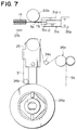
- the double-sided adhesive tape supplying section 23 is lowered to start the predetermined movement of the gripper 31a while holding the first tape-like article Tb as shown in FIG. 7, so that the leading end of the first tape-like article Tb is transferred to the predetermined position of the tape-like article winding unit 4.
- the tape-like article drawing and winding unit 3 provided with the gripper 31a is standing-by at the upward front location of the tape-like article winding unit 4 in winding of the first tape-like article Tb.
- the drawing and winding unit 3 is moved horizontally to the tape-like article gripping position in front of the press roller 22a and the sticking roller 24f.
- the gripper 31a is returned to the stand-by position and downwardly moved therefrom.
- respective first tape-like articles Tb gripped by the four grippers 31a are guided through a guide roller 41b into respective spaces between the three guide plates 41a arranged in parallel at the predetermined intervals and the right and left flanges of the winding spool 6 and are further transferred to the peripheral surfaces of four connected winding spools 6.
- the tape-like article pressing portion 32 When the leading end of the first tape-like article Tb is transferred by the gripper 31a to the peripheral surface of the spool 6, the tape-like article pressing portion 32 is inclined downwardly to push the leading end surface of the first tape-like article onto the peripheral surface of the winding spool 6 by the rollers 32c-1 of the press member 32c, so that the double-sided adhesive tape 5 stuck onto the back surface of the tape-like article is stuck and joined to the peripheral surface of the winding spool 6.
- the tape-like article drawing and winding unit 3 is returned to the stand-by position and the winding unit 4 is actuated to start the winding of the first tape-like article.
- the feeding is stopped and the feed gripper 13 is actuated to project the second tape-like article Ta for the predetermined length through the second guide path 16b into the passage 17a of the movable cutter 17.
- the movable cutter 17 is lifted up to sever firstly the first tape-like article Tb and successively the projected end of the second tape-like aritcle Ta in cooperation with the stationay cutter 16.
- the severed piece of the second tape-like article Ta is projected rearwardly from the severed end of the first tape-like article Tb.
- the severed piece or joint piece of the second tape-like article Ta is attached to the severed end of the first tape-like article Tb and further wound onto the winding spool 6, and when the end of the first tape-like article Tb reaches to the wound surface layer, the tape-like article pressing portion 32 is again actuated to press and join the joint piece of the second tape-like article Ta projected from the wound end of the first tape-like article Tb onto the surface of the wound surface layer to finish the winding operation.
- the leading end and the trailing end of the tape-like article can be automatically and stably guided on the peripheral surface of the desired winding spool.
- the leading and trailing ends of the tape-like article are certainly stuck and joined to the peripheral surface of the conventional usual spool.
Landscapes
- Replacement Of Web Rolls (AREA)
- Adhesive Tape Dispensing Devices (AREA)
- Folding Of Thin Sheet-Like Materials, Special Discharging Devices, And Others (AREA)
- Basic Packing Technique (AREA)
Applications Claiming Priority (2)
| Application Number | Priority Date | Filing Date | Title |
|---|---|---|---|
| JP4227418A JP2672925B2 (ja) | 1992-08-26 | 1992-08-26 | テープ状体の自動巻取機 |
| JP227418/92 | 1992-08-26 |
Publications (2)
| Publication Number | Publication Date |
|---|---|
| EP0585092A1 true EP0585092A1 (de) | 1994-03-02 |
| EP0585092B1 EP0585092B1 (de) | 1997-08-06 |
Family
ID=16860535
Family Applications (1)
| Application Number | Title | Priority Date | Filing Date |
|---|---|---|---|
| EP93306651A Expired - Lifetime EP0585092B1 (de) | 1992-08-26 | 1993-08-23 | Automatische Wickelmaschine für bandartige Produkte |
Country Status (4)
| Country | Link |
|---|---|
| US (1) | US5419511A (de) |
| EP (1) | EP0585092B1 (de) |
| JP (1) | JP2672925B2 (de) |
| DE (1) | DE69312823T2 (de) |
Cited By (1)
| Publication number | Priority date | Publication date | Assignee | Title |
|---|---|---|---|---|
| CN105129470A (zh) * | 2013-12-31 | 2015-12-09 | 黄聪伟 | 具有满料轮自动包装装置的单体生料带自动复卷生产线 |
Families Citing this family (8)
| Publication number | Priority date | Publication date | Assignee | Title |
|---|---|---|---|---|
| US6431497B1 (en) * | 2000-09-08 | 2002-08-13 | Robert P. Hoyt | Failure resistant multiline tether |
| JP4130887B2 (ja) * | 2002-10-03 | 2008-08-06 | 日立オムロンターミナルソリューションズ株式会社 | 紙幣収納放出装置及び紙幣搬送装置 |
| US7028794B2 (en) * | 2003-02-26 | 2006-04-18 | Mitsubishi Denki Kabushiki Kaisha | Transmission gear apparatus for motor vehicle |
| CN106006145A (zh) * | 2016-07-18 | 2016-10-12 | 东莞市坚华机械有限公司 | 一种自动卷带设备 |
| CN214727198U (zh) * | 2019-05-27 | 2021-11-16 | 深圳创怡兴实业有限公司 | 贴胶条装置 |
| EP3747810A1 (de) * | 2019-06-06 | 2020-12-09 | Georg Sahm GmbH & Co. KG | Verfahren zum verbinden von bändern, bänderverbindungseinrichtung, verarbeitungssystem und verwendung |
| KR102506420B1 (ko) * | 2021-03-09 | 2023-03-03 | 주식회사 클레버 | 파우치형 이차전지 테이핑 장치용 테이프 공급 유닛 |
| CN115432502A (zh) * | 2021-06-02 | 2022-12-06 | 泰科电子(上海)有限公司 | 绑带设备 |
Citations (11)
| Publication number | Priority date | Publication date | Assignee | Title |
|---|---|---|---|---|
| DE2138088A1 (de) * | 1971-07-30 | 1973-05-17 | Thaelmann Schwermaschbau Veb | Vorrichtung zum einfuehren von bandmaterial, insbesondere mehrerer bandmaterialstreifen |
| DE2825154A1 (de) * | 1978-06-08 | 1979-12-13 | Ludwig Bruecher & Co Maschinen | Kleinrollenwickelvollautomat |
| EP0036311A1 (de) * | 1980-03-13 | 1981-09-23 | John William Rogers | Mechanisches Überführen einer Materialbahn zu einer Aufwickelvorrichtung |
| JPS61263574A (ja) * | 1985-05-17 | 1986-11-21 | Yoshida Kogyo Kk <Ykk> | テ−プ状体の巻取りスプ−ルおよび巻取り方法 |
| EP0221737A2 (de) * | 1985-10-26 | 1987-05-13 | Yoshida Kogyo K.K. | Vorrichtung zum Abtrennen und Befestigen von Verbindungsstücken |
| DE3806200A1 (de) * | 1988-02-26 | 1989-09-07 | Agfa Gevaert Ag | Vorrichtung zum anwickeln eines filmanfangs an eine aufwickelspule |
| EP0387632A2 (de) * | 1989-03-15 | 1990-09-19 | BASF Magnetics GmbH | Schneide- und Wickelvorrichtung für Folienstreifen |
| WO1991004935A1 (en) * | 1989-10-02 | 1991-04-18 | Eastman Kodak Company | Method and apparatus for taping lead and tail ends of web during winding onto a core |
| US5022597A (en) * | 1989-09-27 | 1991-06-11 | Krantz America, Inc. | Sheet winding apparatus |
| EP0442038A2 (de) * | 1990-02-07 | 1991-08-21 | JAGENBERG Aktiengesellschaft | Verfahren und Vorrichtung zum automatischen Wechseln einer vollen Wickelrolle gegen eine neue Wickelhülse |
| WO1992005100A1 (de) * | 1990-09-14 | 1992-04-02 | Jagenberg Aktiengesellschaft | Verfahren und vorrichtung zum wechseln von wickelrollen |
Family Cites Families (8)
| Publication number | Priority date | Publication date | Assignee | Title |
|---|---|---|---|---|
| ES400106A1 (es) * | 1971-02-27 | 1975-06-16 | Alberto | Perfeccionamientos en una maquina automatica para formar rollos de tejido en pieza. |
| US4094474A (en) * | 1977-03-03 | 1978-06-13 | Rotoflex Engraving Limited | Slitting apparatus |
| DE2724955C2 (de) * | 1977-06-02 | 1983-03-24 | Erwin Kampf Gmbh & Co Maschinenfabrik, 5276 Wiehl | Rollenwickelmaschine zur Bildung von Einzelwickeln |
| ZA775455B (en) * | 1977-08-09 | 1978-07-26 | Kollmorgen Tech Corp | Improved methods and apparatus for making scribed circuit boards |
| JPS58148140A (ja) * | 1982-02-24 | 1983-09-03 | Rengo Co Ltd | サ−フエ−スワインダ |
| JPS58157666A (ja) * | 1982-03-12 | 1983-09-19 | Konishiroku Photo Ind Co Ltd | ウエブ自動巻取装置 |
| JPH078435B2 (ja) * | 1987-07-09 | 1995-02-01 | 松下電器産業株式会社 | 交流ア−ク溶接装置 |
| JPH07108745B2 (ja) * | 1989-11-20 | 1995-11-22 | 住友重機械工業株式会社 | ワインダのコア巻取準備方法および粘着材貼付装置 |
-
1992
- 1992-08-26 JP JP4227418A patent/JP2672925B2/ja not_active Expired - Lifetime
-
1993
- 1993-08-23 DE DE69312823T patent/DE69312823T2/de not_active Expired - Fee Related
- 1993-08-23 EP EP93306651A patent/EP0585092B1/de not_active Expired - Lifetime
- 1993-08-26 US US08/111,877 patent/US5419511A/en not_active Expired - Fee Related
Patent Citations (13)
| Publication number | Priority date | Publication date | Assignee | Title |
|---|---|---|---|---|
| DE2138088A1 (de) * | 1971-07-30 | 1973-05-17 | Thaelmann Schwermaschbau Veb | Vorrichtung zum einfuehren von bandmaterial, insbesondere mehrerer bandmaterialstreifen |
| DE2825154A1 (de) * | 1978-06-08 | 1979-12-13 | Ludwig Bruecher & Co Maschinen | Kleinrollenwickelvollautomat |
| EP0036311A1 (de) * | 1980-03-13 | 1981-09-23 | John William Rogers | Mechanisches Überführen einer Materialbahn zu einer Aufwickelvorrichtung |
| JPS61263574A (ja) * | 1985-05-17 | 1986-11-21 | Yoshida Kogyo Kk <Ykk> | テ−プ状体の巻取りスプ−ルおよび巻取り方法 |
| EP0202591A2 (de) * | 1985-05-17 | 1986-11-26 | Yoshida Kogyo K.K. | Aufwickeln von langgestrecktem biegsamen Material |
| JPH0115283B2 (de) * | 1985-10-26 | 1989-03-16 | Yoshida Kogyo Kk | |
| EP0221737A2 (de) * | 1985-10-26 | 1987-05-13 | Yoshida Kogyo K.K. | Vorrichtung zum Abtrennen und Befestigen von Verbindungsstücken |
| DE3806200A1 (de) * | 1988-02-26 | 1989-09-07 | Agfa Gevaert Ag | Vorrichtung zum anwickeln eines filmanfangs an eine aufwickelspule |
| EP0387632A2 (de) * | 1989-03-15 | 1990-09-19 | BASF Magnetics GmbH | Schneide- und Wickelvorrichtung für Folienstreifen |
| US5022597A (en) * | 1989-09-27 | 1991-06-11 | Krantz America, Inc. | Sheet winding apparatus |
| WO1991004935A1 (en) * | 1989-10-02 | 1991-04-18 | Eastman Kodak Company | Method and apparatus for taping lead and tail ends of web during winding onto a core |
| EP0442038A2 (de) * | 1990-02-07 | 1991-08-21 | JAGENBERG Aktiengesellschaft | Verfahren und Vorrichtung zum automatischen Wechseln einer vollen Wickelrolle gegen eine neue Wickelhülse |
| WO1992005100A1 (de) * | 1990-09-14 | 1992-04-02 | Jagenberg Aktiengesellschaft | Verfahren und vorrichtung zum wechseln von wickelrollen |
Cited By (1)
| Publication number | Priority date | Publication date | Assignee | Title |
|---|---|---|---|---|
| CN105129470A (zh) * | 2013-12-31 | 2015-12-09 | 黄聪伟 | 具有满料轮自动包装装置的单体生料带自动复卷生产线 |
Also Published As
| Publication number | Publication date |
|---|---|
| DE69312823T2 (de) | 1998-02-19 |
| EP0585092B1 (de) | 1997-08-06 |
| JPH0672620A (ja) | 1994-03-15 |
| JP2672925B2 (ja) | 1997-11-05 |
| US5419511A (en) | 1995-05-30 |
| DE69312823D1 (de) | 1997-09-11 |
Similar Documents
| Publication | Publication Date | Title |
|---|---|---|
| US4157794A (en) | Device and method for rolling up continuous sheets | |
| US4278489A (en) | Web splicing apparatus | |
| JPH0479893B2 (de) | ||
| EP1008543B1 (de) | Vorrichtung zum Formen einer Spleissverbindung in einer Papierbahn | |
| JPS6356143B2 (de) | ||
| EP0585092B1 (de) | Automatische Wickelmaschine für bandartige Produkte | |
| JP2005514292A (ja) | シート材料のロールにスプライシングテープを貼付する方法および装置 | |
| US4555070A (en) | Method and apparatus for unwinding and splicing successive rolls | |
| US5288361A (en) | Apparatus for splicing of a continuous packaging web | |
| KR20030077411A (ko) | 필름 포장기 | |
| EP1149788A2 (de) | Vorrichtung zum Spleissen von Wellpappe, Wellpappenmaschine, und Verfahren zum Spleissen von Wellpappe | |
| CN212503165U (zh) | 一种卷轴、卷材卡爪组件以及卷材机器人 | |
| US5305965A (en) | Apparatus for winding and storing a tape-like article in a container | |
| KR19990070826A (ko) | 레이블 권회장치 | |
| JP4342015B2 (ja) | ラベル供給装置 | |
| JP2786537B2 (ja) | ウェブ材料ストリップのスプール巻き装置 | |
| JPWO1996035345A1 (ja) | スライドファスナーの製造方法 | |
| GB2037262A (en) | Web splicing apparatus | |
| JPS61123416A (ja) | 巻取り機 | |
| EP0463461B1 (de) | Verfahren und Gerät zum Aufwickeln eines Magnetbandes | |
| JPH1095408A (ja) | 帯状材の接続装置 | |
| EP0567718B1 (de) | Einheit zum Schneiden und Verbinden für ein automatisches Kassettenladegerät und damit durchgeführtes Verfahren zum Bandladen | |
| JPH09278237A (ja) | 長尺物シート同士の接続方法と装置 | |
| JPH0720792B2 (ja) | テープの連続的フィード方法と装置 | |
| JPH026033Y2 (de) |
Legal Events
| Date | Code | Title | Description |
|---|---|---|---|
| PUAI | Public reference made under article 153(3) epc to a published international application that has entered the european phase |
Free format text: ORIGINAL CODE: 0009012 |
|
| AK | Designated contracting states |
Kind code of ref document: A1 Designated state(s): DE FR GB IT |
|
| 17P | Request for examination filed |
Effective date: 19940615 |
|
| RAP1 | Party data changed (applicant data changed or rights of an application transferred) |
Owner name: YKK CORPORATION |
|
| 17Q | First examination report despatched |
Effective date: 19960122 |
|
| GRAG | Despatch of communication of intention to grant |
Free format text: ORIGINAL CODE: EPIDOS AGRA |
|
| GRAH | Despatch of communication of intention to grant a patent |
Free format text: ORIGINAL CODE: EPIDOS IGRA |
|
| GRAH | Despatch of communication of intention to grant a patent |
Free format text: ORIGINAL CODE: EPIDOS IGRA |
|
| GRAA | (expected) grant |
Free format text: ORIGINAL CODE: 0009210 |
|
| AK | Designated contracting states |
Kind code of ref document: B1 Designated state(s): DE FR GB IT |
|
| ITF | It: translation for a ep patent filed | ||
| REF | Corresponds to: |
Ref document number: 69312823 Country of ref document: DE Date of ref document: 19970911 |
|
| ET | Fr: translation filed | ||
| PLBE | No opposition filed within time limit |
Free format text: ORIGINAL CODE: 0009261 |
|
| STAA | Information on the status of an ep patent application or granted ep patent |
Free format text: STATUS: NO OPPOSITION FILED WITHIN TIME LIMIT |
|
| 26N | No opposition filed | ||
| PGFP | Annual fee paid to national office [announced via postgrant information from national office to epo] |
Ref country code: FR Payment date: 20010810 Year of fee payment: 9 |
|
| PGFP | Annual fee paid to national office [announced via postgrant information from national office to epo] |
Ref country code: DE Payment date: 20010813 Year of fee payment: 9 |
|
| PGFP | Annual fee paid to national office [announced via postgrant information from national office to epo] |
Ref country code: GB Payment date: 20010822 Year of fee payment: 9 |
|
| REG | Reference to a national code |
Ref country code: GB Ref legal event code: IF02 |
|
| PG25 | Lapsed in a contracting state [announced via postgrant information from national office to epo] |
Ref country code: GB Free format text: LAPSE BECAUSE OF NON-PAYMENT OF DUE FEES Effective date: 20020823 |
|
| PG25 | Lapsed in a contracting state [announced via postgrant information from national office to epo] |
Ref country code: DE Free format text: LAPSE BECAUSE OF NON-PAYMENT OF DUE FEES Effective date: 20030301 |
|
| GBPC | Gb: european patent ceased through non-payment of renewal fee |
Effective date: 20020823 |
|
| PG25 | Lapsed in a contracting state [announced via postgrant information from national office to epo] |
Ref country code: FR Free format text: LAPSE BECAUSE OF NON-PAYMENT OF DUE FEES Effective date: 20030430 |
|
| REG | Reference to a national code |
Ref country code: FR Ref legal event code: ST |
|
| PG25 | Lapsed in a contracting state [announced via postgrant information from national office to epo] |
Ref country code: IT Free format text: LAPSE BECAUSE OF NON-PAYMENT OF DUE FEES Effective date: 20050823 |