EP0583085A2 - Gerät zum Positionieren für Mehrspindelbearbeitungen - Google Patents
Gerät zum Positionieren für Mehrspindelbearbeitungen Download PDFInfo
- Publication number
- EP0583085A2 EP0583085A2 EP93305664A EP93305664A EP0583085A2 EP 0583085 A2 EP0583085 A2 EP 0583085A2 EP 93305664 A EP93305664 A EP 93305664A EP 93305664 A EP93305664 A EP 93305664A EP 0583085 A2 EP0583085 A2 EP 0583085A2
- Authority
- EP
- European Patent Office
- Prior art keywords
- spindle
- movement
- machining
- rail
- saddle
- Prior art date
- Legal status (The legal status is an assumption and is not a legal conclusion. Google has not performed a legal analysis and makes no representation as to the accuracy of the status listed.)
- Granted
Links
- 238000003754 machining Methods 0.000 title claims abstract description 48
- 230000001133 acceleration Effects 0.000 claims abstract description 12
- 239000002131 composite material Substances 0.000 claims description 10
- OKTJSMMVPCPJKN-UHFFFAOYSA-N Carbon Chemical class [C] OKTJSMMVPCPJKN-UHFFFAOYSA-N 0.000 claims description 9
- 238000005520 cutting process Methods 0.000 claims description 8
- 239000010439 graphite Substances 0.000 claims description 8
- 229910002804 graphite Inorganic materials 0.000 claims description 8
- 238000000034 method Methods 0.000 claims description 7
- 230000002706 hydrostatic effect Effects 0.000 claims description 6
- 239000000463 material Substances 0.000 claims description 3
- 239000013598 vector Substances 0.000 claims description 3
- 230000000295 complement effect Effects 0.000 claims 2
- 238000001816 cooling Methods 0.000 claims 2
- 238000003287 bathing Methods 0.000 claims 1
- 239000012530 fluid Substances 0.000 claims 1
- 239000002184 metal Substances 0.000 claims 1
- 230000000712 assembly Effects 0.000 description 9
- 238000000429 assembly Methods 0.000 description 9
- 230000008859 change Effects 0.000 description 9
- 238000012546 transfer Methods 0.000 description 6
- 238000010276 construction Methods 0.000 description 5
- 230000007246 mechanism Effects 0.000 description 3
- 238000012986 modification Methods 0.000 description 3
- 230000004048 modification Effects 0.000 description 3
- 229910000831 Steel Inorganic materials 0.000 description 2
- 230000008878 coupling Effects 0.000 description 2
- 238000010168 coupling process Methods 0.000 description 2
- 238000005859 coupling reaction Methods 0.000 description 2
- 238000013461 design Methods 0.000 description 2
- 239000004744 fabric Substances 0.000 description 2
- 238000003780 insertion Methods 0.000 description 2
- 230000037431 insertion Effects 0.000 description 2
- 230000002441 reversible effect Effects 0.000 description 2
- 239000007787 solid Substances 0.000 description 2
- 239000010959 steel Substances 0.000 description 2
- XAGFODPZIPBFFR-UHFFFAOYSA-N aluminium Chemical compound [Al] XAGFODPZIPBFFR-UHFFFAOYSA-N 0.000 description 1
- 229910052782 aluminium Inorganic materials 0.000 description 1
- 239000004411 aluminium Substances 0.000 description 1
- 230000004888 barrier function Effects 0.000 description 1
- 238000005266 casting Methods 0.000 description 1
- 238000005553 drilling Methods 0.000 description 1
- 230000009977 dual effect Effects 0.000 description 1
- 239000010438 granite Substances 0.000 description 1
- 238000012423 maintenance Methods 0.000 description 1
- 238000004519 manufacturing process Methods 0.000 description 1
- 238000003801 milling Methods 0.000 description 1
Images


Classifications
-
- B—PERFORMING OPERATIONS; TRANSPORTING
- B23—MACHINE TOOLS; METAL-WORKING NOT OTHERWISE PROVIDED FOR
- B23Q—DETAILS, COMPONENTS, OR ACCESSORIES FOR MACHINE TOOLS, e.g. ARRANGEMENTS FOR COPYING OR CONTROLLING; MACHINE TOOLS IN GENERAL CHARACTERISED BY THE CONSTRUCTION OF PARTICULAR DETAILS OR COMPONENTS; COMBINATIONS OR ASSOCIATIONS OF METAL-WORKING MACHINES, NOT DIRECTED TO A PARTICULAR RESULT
- B23Q39/00—Metal-working machines incorporating a plurality of sub-assemblies, each capable of performing a metal-working operation
- B23Q39/02—Metal-working machines incorporating a plurality of sub-assemblies, each capable of performing a metal-working operation the sub-assemblies being capable of being brought to act at a single operating station
- B23Q39/021—Metal-working machines incorporating a plurality of sub-assemblies, each capable of performing a metal-working operation the sub-assemblies being capable of being brought to act at a single operating station with a plurality of toolheads per workholder, whereby the toolhead is a main spindle, a multispindle, a revolver or the like
- B23Q39/025—Metal-working machines incorporating a plurality of sub-assemblies, each capable of performing a metal-working operation the sub-assemblies being capable of being brought to act at a single operating station with a plurality of toolheads per workholder, whereby the toolhead is a main spindle, a multispindle, a revolver or the like with different working directions of toolheads on same workholder
- B23Q39/026—Metal-working machines incorporating a plurality of sub-assemblies, each capable of performing a metal-working operation the sub-assemblies being capable of being brought to act at a single operating station with a plurality of toolheads per workholder, whereby the toolhead is a main spindle, a multispindle, a revolver or the like with different working directions of toolheads on same workholder simultaneous working of toolheads
-
- B—PERFORMING OPERATIONS; TRANSPORTING
- B23—MACHINE TOOLS; METAL-WORKING NOT OTHERWISE PROVIDED FOR
- B23Q—DETAILS, COMPONENTS, OR ACCESSORIES FOR MACHINE TOOLS, e.g. ARRANGEMENTS FOR COPYING OR CONTROLLING; MACHINE TOOLS IN GENERAL CHARACTERISED BY THE CONSTRUCTION OF PARTICULAR DETAILS OR COMPONENTS; COMBINATIONS OR ASSOCIATIONS OF METAL-WORKING MACHINES, NOT DIRECTED TO A PARTICULAR RESULT
- B23Q1/00—Members which are comprised in the general build-up of a form of machine, particularly relatively large fixed members
- B23Q1/01—Frames, beds, pillars or like members; Arrangement of ways
- B23Q1/015—Frames, beds, pillars
-
- Y—GENERAL TAGGING OF NEW TECHNOLOGICAL DEVELOPMENTS; GENERAL TAGGING OF CROSS-SECTIONAL TECHNOLOGIES SPANNING OVER SEVERAL SECTIONS OF THE IPC; TECHNICAL SUBJECTS COVERED BY FORMER USPC CROSS-REFERENCE ART COLLECTIONS [XRACs] AND DIGESTS
- Y10—TECHNICAL SUBJECTS COVERED BY FORMER USPC
- Y10T—TECHNICAL SUBJECTS COVERED BY FORMER US CLASSIFICATION
- Y10T29/00—Metal working
- Y10T29/49—Method of mechanical manufacture
- Y10T29/49995—Shaping one-piece blank by removing material
- Y10T29/49996—Successive distinct removal operations
-
- Y—GENERAL TAGGING OF NEW TECHNOLOGICAL DEVELOPMENTS; GENERAL TAGGING OF CROSS-SECTIONAL TECHNOLOGIES SPANNING OVER SEVERAL SECTIONS OF THE IPC; TECHNICAL SUBJECTS COVERED BY FORMER USPC CROSS-REFERENCE ART COLLECTIONS [XRACs] AND DIGESTS
- Y10—TECHNICAL SUBJECTS COVERED BY FORMER USPC
- Y10T—TECHNICAL SUBJECTS COVERED BY FORMER US CLASSIFICATION
- Y10T29/00—Metal working
- Y10T29/51—Plural diverse manufacturing apparatus including means for metal shaping or assembling
- Y10T29/5104—Type of machine
- Y10T29/5105—Drill press
- Y10T29/5107—Drilling and other
-
- Y—GENERAL TAGGING OF NEW TECHNOLOGICAL DEVELOPMENTS; GENERAL TAGGING OF CROSS-SECTIONAL TECHNOLOGIES SPANNING OVER SEVERAL SECTIONS OF THE IPC; TECHNICAL SUBJECTS COVERED BY FORMER USPC CROSS-REFERENCE ART COLLECTIONS [XRACs] AND DIGESTS
- Y10—TECHNICAL SUBJECTS COVERED BY FORMER USPC
- Y10T—TECHNICAL SUBJECTS COVERED BY FORMER US CLASSIFICATION
- Y10T408/00—Cutting by use of rotating axially moving tool
- Y10T408/03—Processes
-
- Y—GENERAL TAGGING OF NEW TECHNOLOGICAL DEVELOPMENTS; GENERAL TAGGING OF CROSS-SECTIONAL TECHNOLOGIES SPANNING OVER SEVERAL SECTIONS OF THE IPC; TECHNICAL SUBJECTS COVERED BY FORMER USPC CROSS-REFERENCE ART COLLECTIONS [XRACs] AND DIGESTS
- Y10—TECHNICAL SUBJECTS COVERED BY FORMER USPC
- Y10T—TECHNICAL SUBJECTS COVERED BY FORMER US CLASSIFICATION
- Y10T408/00—Cutting by use of rotating axially moving tool
- Y10T408/91—Machine frame
-
- Y—GENERAL TAGGING OF NEW TECHNOLOGICAL DEVELOPMENTS; GENERAL TAGGING OF CROSS-SECTIONAL TECHNOLOGIES SPANNING OVER SEVERAL SECTIONS OF THE IPC; TECHNICAL SUBJECTS COVERED BY FORMER USPC CROSS-REFERENCE ART COLLECTIONS [XRACs] AND DIGESTS
- Y10—TECHNICAL SUBJECTS COVERED BY FORMER USPC
- Y10T—TECHNICAL SUBJECTS COVERED BY FORMER US CLASSIFICATION
- Y10T409/00—Gear cutting, milling, or planing
- Y10T409/30—Milling
- Y10T409/303752—Process
- Y10T409/303808—Process including infeeding
-
- Y—GENERAL TAGGING OF NEW TECHNOLOGICAL DEVELOPMENTS; GENERAL TAGGING OF CROSS-SECTIONAL TECHNOLOGIES SPANNING OVER SEVERAL SECTIONS OF THE IPC; TECHNICAL SUBJECTS COVERED BY FORMER USPC CROSS-REFERENCE ART COLLECTIONS [XRACs] AND DIGESTS
- Y10—TECHNICAL SUBJECTS COVERED BY FORMER USPC
- Y10T—TECHNICAL SUBJECTS COVERED BY FORMER US CLASSIFICATION
- Y10T409/00—Gear cutting, milling, or planing
- Y10T409/30—Milling
- Y10T409/306664—Milling including means to infeed rotary cutter toward work
- Y10T409/307728—Milling including means to infeed rotary cutter toward work including gantry-type cutter-carrier
-
- Y—GENERAL TAGGING OF NEW TECHNOLOGICAL DEVELOPMENTS; GENERAL TAGGING OF CROSS-SECTIONAL TECHNOLOGIES SPANNING OVER SEVERAL SECTIONS OF THE IPC; TECHNICAL SUBJECTS COVERED BY FORMER USPC CROSS-REFERENCE ART COLLECTIONS [XRACs] AND DIGESTS
- Y10—TECHNICAL SUBJECTS COVERED BY FORMER USPC
- Y10T—TECHNICAL SUBJECTS COVERED BY FORMER US CLASSIFICATION
- Y10T409/00—Gear cutting, milling, or planing
- Y10T409/30—Milling
- Y10T409/30784—Milling including means to adustably position cutter
- Y10T409/307952—Linear adjustment
- Y10T409/308288—Linear adjustment including gantry-type cutter-carrier
-
- Y—GENERAL TAGGING OF NEW TECHNOLOGICAL DEVELOPMENTS; GENERAL TAGGING OF CROSS-SECTIONAL TECHNOLOGIES SPANNING OVER SEVERAL SECTIONS OF THE IPC; TECHNICAL SUBJECTS COVERED BY FORMER USPC CROSS-REFERENCE ART COLLECTIONS [XRACs] AND DIGESTS
- Y10—TECHNICAL SUBJECTS COVERED BY FORMER USPC
- Y10T—TECHNICAL SUBJECTS COVERED BY FORMER US CLASSIFICATION
- Y10T483/00—Tool changing
- Y10T483/10—Process
-
- Y—GENERAL TAGGING OF NEW TECHNOLOGICAL DEVELOPMENTS; GENERAL TAGGING OF CROSS-SECTIONAL TECHNOLOGIES SPANNING OVER SEVERAL SECTIONS OF THE IPC; TECHNICAL SUBJECTS COVERED BY FORMER USPC CROSS-REFERENCE ART COLLECTIONS [XRACs] AND DIGESTS
- Y10—TECHNICAL SUBJECTS COVERED BY FORMER USPC
- Y10T—TECHNICAL SUBJECTS COVERED BY FORMER US CLASSIFICATION
- Y10T483/00—Tool changing
- Y10T483/16—Tool changing with means to transfer work
- Y10T483/165—Plural machine tools, e.g., flexible manufacturing
-
- Y—GENERAL TAGGING OF NEW TECHNOLOGICAL DEVELOPMENTS; GENERAL TAGGING OF CROSS-SECTIONAL TECHNOLOGIES SPANNING OVER SEVERAL SECTIONS OF THE IPC; TECHNICAL SUBJECTS COVERED BY FORMER USPC CROSS-REFERENCE ART COLLECTIONS [XRACs] AND DIGESTS
- Y10—TECHNICAL SUBJECTS COVERED BY FORMER USPC
- Y10T—TECHNICAL SUBJECTS COVERED BY FORMER US CLASSIFICATION
- Y10T483/00—Tool changing
- Y10T483/17—Tool changing including machine tool or component
- Y10T483/1733—Rotary spindle machine tool [e.g., milling machine, boring, machine, grinding machine, etc.]
Definitions
- the invention relates to positioning assemblies using electrical linear motors and, more particularly, to such assemblies that accelerate and decelerate a movable working element at a rate approaching or exceeding one G.
- Improving such positioning assemblies requires breaking the productivity barrier in machining a variety of surfaces and configurations on a given workpiece without dedicated tooling clusters, and to do so with more than one cutting tool that is independently positioned but simultaneously controlled.
- High-volume prior art machining lines providing 500,000 machined units per year, or more, of one type, are not economical if marketing demand for such workpiece drops.
- Such lines may use multiple-spindle turret heads which are costly to change when modifying the line to machine other workpieces, and are limited to only one of either drilling, boring, or milling.
- Such problem can be overcome by use of multiple-spindle machines having positioning accelerations many times faster than commercial machining cells.
- a high degree of flexibility can be achieved by eliminating product-specific worktables, dedicated cutting heads requiring replacement when workpiece changes are made, and utilising unprecedented speeds not only to complete machining tasks but to change tools or fixtures from an adjacent inventory. Timing for changing to a new product (workpiece) can be substantially reduced, requiring only software control modifications.
- Magnetic loading to increase guidance of a linear motor assembly has been used in conjunction with sliding or roller bearings (see U.S. patents 4,505,464 and 4,985,651). Magnetic loading of bearings does little to enhance stiffness because it is imprecise and weak; magnetic loading is primarily suited to a use that assists in following more closely a guided track and therefore does little to promote stiffness of the linear motor assembly.
- the invention in a first aspect, is a positioning apparatus for multiple-spindle machining.
- the apparatus comprises: (a) a plurality of upstanding columns rigidly interconnected to a common platform and aligned parallel to each other and perpendicular to the platform within an accuracy of ⁇ .0005 inches; (b) rail means extending between each of the columns along the periphery defined by the footprint of the columns for providing movable support and having bearing means on the columns providing for movement of each rail means along the Y-axis; (c) other movement means slidable on each of the rail means along at least another axis of movement; (d) linear motor means for selectively moving the rail means and other movement means along said respective Y and another axis at peak accelerations or decelerations of about 1-2 G's; and (d) spindle means on each ram having a spindle rotationally driven about an S-axis thereof.
- Each of the plurality of spindles is rapidly positioned to enter a cubed machining space through a
- the invention is a method of machining simultaneously a sequence of surfaces on each of multiple sides of a workpiece, comprising: (a) supporting a plurality of rotary-driven spindles, each carrying a cutting tool, each spindle being supported by a plurality of relatively movable elements that provide for movement into and out of a predetermined sized, cubed machining space, such support providing for spindle movement having vectors along at least mutually perpendicular axes; (b) placing the workpiece in the machining space at a predetermined location; (c) actuating relative movement of the elements by use of linear motors to accurately position each spindle for simultaneous machining of first surfaces on separate sides of the workpiece; and (d) actuating the elements by use of said linear motors to reposition the plurality of spindles for simultaneous machining of other surfaces on each of the sides of the workpiece.
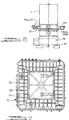
- Such apparatus comprises a plurality of columns B; rails assemblies C (here four in number: C-1 through C-4), stationed between columns and movable along a Y-axis; saddle assembly D on each rail assembly movable along an X-axis; ram assembly E on each said saddle assembly D (carrying a spindle F, rotational about an S-axis, to enter each upright side of a cubed machining space I); a superstructure G laying across the columns and supporting a flexible assembly H movable in X and Z axes and about an A axis to enter and carry a spindle J through the top side of the machining space I; linear motor assemblies M for selectively moving the assemblies C, D, E, and H to position and feed the spindles F and J; adjustable and movable workpiece support K and tool inventory L for the vertical spindle J and a tool inventory N for horizontal
- the apparatus in Figure 1 has five spindles: four horizontally oriented spindles (1-4) arranged to independently enter an upright side of the cubed machining space I, and one vertically oriented spindle (5) arranged to independently enter the top of the cubed machining space I.
- the apparatus is capable of simultaneously rapidly and accurately positioning each of such spindles within such space at accelerations/decelerations of about 1-2 G's.
- the apparatus is also capable of simultaneously or selectively moving the spindles at slower feed rates to carry out machining of faces 11 of the workpiece 12 aligned or juxtaposed with each of the various sides 13, 14, 15, 16, and 17 of the machining space.
- the spindles F and J can be repositioned individually and concurrently to carry out machining of sequential tasks along the respective workpiece faces 11 associated with a spindle. Moreover, the spindles can be extremely rapidly withdrawn from the cubed machining space I to carry out a quick tool exchange with apparatus L or N within a timespan of about less than about four seconds.
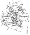
- Such plurality of spindles may be less than five, such as shown in the alternative embodiment in Figure 8, or more than five spindles.
- the latter variation increases the difficulty of placing independently movable support means for each of such spindles within a given envelope surrounding the machining space.
- the four columns B for the machine are heavy-duty steel weldments, although any rigid and vibration-absorbing construction may be utilised; they should be aligned to ⁇ .0005 inch. These columns are supported on precision levelling devices 19 that are located on the machine foundation. These columns support all movable assemblies C, D, E, and H; due to the massive nature of such columns, deflections are reduced. The levelling devices under the columns allow the columns to be aligned to each other, and the Y-axis slideways can be realigned on the columns.
- Each rail assembly has a beam or rail 18 extending between the columns, along the column footprint periphery, and is carried by two Y-axis slides 20, 21 (see Figure 3).
- Each beam 18 is constructed of high-strength graphite composite material in a triangular cross-sectional configuration (see Figure 4), bulkheads 22 are configured as honeycomb cells faced with composite material cloth 23, and the saddle 24 has outside panels of solid graphite composite material.
- the graphite composite preferably should have its graphite fibres arranged to give homogeneous orientation.
- the beam 25, used to support the upper spindle J is the same in construction as the beams used for the horizontal spindles except that it is shorter.
- Each beam may be provided with a rotary joint that allows the ram assembly E to pivot with respect to the work cube.
- a beam can be rotated by dual A-axis drive motors, one located on each end of the beam; the drive motors would turn a worm that is engaged with a worm gear mounted in the Y-axis slide.
- the worm gear can be carried on a pair of angular contact precision ball bearings and rotary feedback scales could be mounted on each end of the beam with the drive motors driving against one another during the final positioning of the beam to remove all of the backlash.
- the beam could then clamped into position by a precision face coupling; such clamping can be done on the A-axis because it is not a contouring axis.
- Each Y-axis slide 20, 21 is located at each end of the beam.
- Each of the Y-axis slides 20, 21 are constructed as a high-strength aluminium casting and each slide is carried on roller bearings 29. These bearings run on a dovetail way surface 30 that is adjustable on the column to allow for realignment of the way surface if it is ever required.
- the slides are powered by linear motors M-1 with coils 26 mounted on the Y-axis slide. Magnets 27 for the motor are located on the column.
- a linear inductosyn scale 28 for the Y-axis slide is located between the motor and the guideway.
- Each beam is counterbalanced by two air cylinders 31, and each slide is also equipped with a brake that will keep the slide from falling when power is removed from the slide.
- the slides are independent linear motor actuated and provide the required high acceleration/deceleration and velocity characteristics.
- the software of the controller, as shown in Figure 9, for the linear motor is designed to prevent skewing of each of the beams.
- Each saddle assembly D has an X-axis saddle 24 uniquely wrapped around the beam cross-section.
- the saddle is constructed of high-strength graphite composite panel material; the panels are mechanically joined at their intersection for ease of maintenance and enhanced stiffness.
- the saddle assembly also has a tunnel 32 securely sitting on the saddle, also of graphite composite material.
- the linear motors 33 and 34 that power the ram 35 and the saddle 24 respectively are carried on the saddle assembly D.
- the motors 34 are symmetrically located on two sides 36 and 37 of the triangular beam 18 and on two sides 38, 39 of the triangular tunnel 32 that supports the saddle on the beam.
- a linear feedback scale 40 (Inductsyn) for the saddle is centrally located on the third side 41 of the beam 18 and a feedback scale 42 is located in a similar manner on the interior of tunnel 32.
- the saddle 24 carries hydrostatic bearings 43 that support the saddle on the beam 18 and also carries hydrostatic bearings 44 on the tunnel to support the ram 35 therein.
- the ram assembly E has a ram 35 fabricated of high-strength graphite composite material with outside panels of solid composite and the intermediate bulkheads as a honeycomb material faced with composite cloth.
- the magnets 45 for the linear motors 33 are symmetrically placed on two of the surfaces of the ram triangular structure.
- the Z-axis ram 35 carries the machine spindle.
- the linear feedback scale 42 for the ram is mounted at the third side of the ram. This provides a centrally located feedback device that is in line with the spindle and the motors.
- the superstructure G is constructed of heavy-duty steel fabrication and rigidly supported by the four columns.
- X-axis slides 45 for the flex assembly H move in a horizontal direction and connect opposite ends of the rail 25 to rigid ways 47, 48.
- the slides have roller bearings to carry the rial on the ways.
- the saddle 49 and tunnel 50 are similar to those used on the other assemblies except that saddle provides for A-axis movement and the tunnel Z-axis movement. All of the previously stated features apply to the upper flexible assembly.
- the tool inventory or changer L for the vertically oriented spindle J consists of a rotating tool magazine 80 supported for rotation on a column 81 and bore 82; a change arm 83 is supported at 84 by head structure 85 for reversible 180 rotation movements. Grippers 86 and 87 at opposite ends of the arm 83 are actuatable to grab a tool from magazine 80 at station 88. The arm 83 is rotated 180 and presents the tool for transfer to spindle J which is lowered to align with the tool and mechanically connect by insertion into the tool holder.
- the tool inventory or changer N for the horizontally disposed spindles F is provided as a free-standing tray structure and is not physically connected to the machine (see Figures 6 and 7). It is designed to provide easy operator access to the 24-tool magazine 52 from floor level.
- the tool magazine is set at an elevation suitable to the required level for tool changing and access by the head of a spindle F. No tool change arm is necessary to reach the tool magazine 52; the spindles F are positioned to be inserted into the holder of a tool 55 as it sits in the magazine pocket 54.
- the tool search and replacement of the tool in the magazine is internal to the machining cycle.
- the result is that the only part of the tool change cycle that is part of the machining cycle is the removal of a tool 55 from the spindle by insertion of the spindle into the tool holder and withdrawal of the spindle from the magazine.
- the estimated time for tool change, chip-to-chip, is about 10.3 seconds.
- a cell worktable 56 is centrally located inside of the machining cell 10. It is mounted on the W-axis slide 57 and has a travel of about 12 inches in both perpendicular directions from the centre of the cell. This does not require the worktable to leave the slide and only requires one table per cell.
- the worktable has a coupling which allows it to be adjustable in horizontally rotational increments of one-half degree.
- a modification of the design of the machining cell 10 is the concept of carrying all of the tools 55 required for a particular operation on a pallet that is transferred onto the worktable with the fixtured workpiece 59.
- the pallet fits onto the worktable in a drawer-type design that also is the mechanism for clamping the pallet to the worktable.
- the pallet is spring-clamped and power-unclamped to ensure clamping of the pallet if there is a loss of power.
- the pallet is located on the top of the worktable by at least three pins. Two of the pins are pallet locators and the third pin is to crowd the pallet into the same location on the locator pins before it is clamped. This allows each tool tray to be custom designed for tools that are required for one side of the workpiece.
- the tools rotate on the worktable with the workpiece. Since the tools are carried on the pallet, there is no need to have a tool changer for the horizontal spindles.
- the tools are changed by positioning the spindle in front of the required tool, clamping the tool onto the spindle, and moving the spindle in the vertical direction to lift the tool out of the tool support.
- the tool is returned to the tool support in the same manner.
- the result is a fast tool change without a tool changer.
- the estimated time for a tool change, chip-to-chip is 5.7 seconds.
- the transfer concept for such modification is to move the pallet through the machine, in one side and out the other. This allows the pallet to be transferred from an unclamped station (on a low-cost cell automation) to the fixture unload area.
- the pallet may be placed on a transfer car outside the machining cell and transferred into the cell on rails.
- the transfer may also be powered by ball screw drivers or by electric linear motors.
- the change transfer mechanism is located on the top of the car and, when the car is in position, the pallet is raised to match the worktable, transferred onto the worktable, and then clamped on the table as previously described.
- the pallets are removed from the worktable in the reverse steps that are described above. Pallet transfer may take approximately 20 seconds.
- a feature of this invention is the use of tandem coordinated slides for raising or moving a rail.
- An alternative embodiment, shown in Figure 8, uses tandem slides 60, 61, but operating with tandem rails 62, 63 extending between concrete columns B; the embodiment of Figure 8 also limits the multiple of spindles to three.
- the bearing and linear motor interface construction between the slides 60, 61 and rails 62, 63 can be the same as described for the preferred embodiment.
- the saddle 64, tunnel 65, and ram 66 construction is also similar to that of the preferred embodiment except that (i) the saddle 64 rides on an upright beam 67 extending between and supported by the slides 61, 62; and (ii) the motors and scales are arranged along one surface or face of the rails 62, 63 or ram 66.
- Ram 66 carry horizontally oriented spindles 73, 74. Coupled to each of the upper slides 61 is a stub rail 68 upon which is mounted a pair of slides 69 for supporting a horizontal rail 70 which in turn is used to carry a movable assembly 71 having a vertically oriented spindle 72. Suitable bearing and linear motor actuating apparatus is deployed between slides 69 and rail 68.
- the method of this invention for simultaneously machining a sequence of surface on each of multiple sides of a workpiece comprises: (a) supporting a plurality of rotary-driven spindles, each carrying a cutting tool, each spindle being supported by a plurality of relatively movable elements that provide for movement into and out of a predetermined sized, cubed machining space, such support providing for spindle movement having vectors along at least mutually perpendicular axes; (b) placing said workpiece in said machining space at a predetermined location; (c) actuating relative movement of said elements by use of linear motors to accurately position each spindle for simultaneous machining of first surfaces on each side of said workpiece; and (d) actuating said elements by use of said linear motors to reposition said plurality of spindles for simultaneously machining other surfaces on each side of said workpiece.
Landscapes
- Engineering & Computer Science (AREA)
- Mechanical Engineering (AREA)
- Machine Tool Units (AREA)
- Turning (AREA)
Priority Applications (1)
| Application Number | Priority Date | Filing Date | Title |
|---|---|---|---|
| EP97117026A EP0819499A3 (de) | 1992-07-31 | 1993-07-19 | Verfahren für Mehrspindelbearbeitungen |
Applications Claiming Priority (2)
| Application Number | Priority Date | Filing Date | Title |
|---|---|---|---|
| US07/923,436 US5314397A (en) | 1992-07-31 | 1992-07-31 | Positioning apparatus for multiple-spindle machining |
| US923436 | 2004-08-20 |
Related Child Applications (1)
| Application Number | Title | Priority Date | Filing Date |
|---|---|---|---|
| EP97117026A Division EP0819499A3 (de) | 1992-07-31 | 1993-07-19 | Verfahren für Mehrspindelbearbeitungen |
Publications (3)
| Publication Number | Publication Date |
|---|---|
| EP0583085A2 true EP0583085A2 (de) | 1994-02-16 |
| EP0583085A3 EP0583085A3 (de) | 1995-08-09 |
| EP0583085B1 EP0583085B1 (de) | 1998-10-21 |
Family
ID=25448686
Family Applications (2)
| Application Number | Title | Priority Date | Filing Date |
|---|---|---|---|
| EP93305664A Expired - Lifetime EP0583085B1 (de) | 1992-07-31 | 1993-07-19 | Gerät zum Positionieren für Mehrspindelbearbeitungen |
| EP97117026A Withdrawn EP0819499A3 (de) | 1992-07-31 | 1993-07-19 | Verfahren für Mehrspindelbearbeitungen |
Family Applications After (1)
| Application Number | Title | Priority Date | Filing Date |
|---|---|---|---|
| EP97117026A Withdrawn EP0819499A3 (de) | 1992-07-31 | 1993-07-19 | Verfahren für Mehrspindelbearbeitungen |
Country Status (6)
| Country | Link |
|---|---|
| US (2) | US5314397A (de) |
| EP (2) | EP0583085B1 (de) |
| JP (1) | JPH06155203A (de) |
| CA (1) | CA2101406A1 (de) |
| DE (1) | DE69321674T2 (de) |
| MX (1) | MX9304376A (de) |
Cited By (7)
| Publication number | Priority date | Publication date | Assignee | Title |
|---|---|---|---|---|
| EP0742072A3 (de) * | 1995-05-12 | 1996-11-27 | Ingersoll Milling Machine Co | |
| EP0933162A3 (de) * | 1998-01-30 | 2001-05-23 | J.G. Weisser Söhne Werkzeugmaschinenfabrik GmbH & Co. KG | Werkzeugmaschine |
| WO2002028592A1 (en) * | 2000-10-03 | 2002-04-11 | Camozzi Holding S.P.A. | Multi-axis linear motor machine tool |
| US6745098B2 (en) | 2000-12-13 | 2004-06-01 | Shapex Solid Image Systems Lp | Machining based on master program merged from parts programs |
| IT201800004269A1 (it) * | 2018-04-06 | 2019-10-06 | Valter Ferlin | Unita' di foratura e contemporanea fresatura su un unico elemento, particolarmente ma non esclusivamente nel settore della produzione di stampi per materie plastiche. |
| IT201800004266A1 (it) * | 2018-04-06 | 2019-10-06 | Valter Ferlin | Unita' di foratura e contemporanea fresatura su un unico elemento, particolarmente ma non esclusivamente nel settore della produzione di stampi per materie plastiche |
| WO2024101991A1 (en) * | 2022-11-10 | 2024-05-16 | Voortman Steel Machinery Holding B.V. | Machining assembly and method of exchanging a machining tool |
Families Citing this family (30)
| Publication number | Priority date | Publication date | Assignee | Title |
|---|---|---|---|---|
| DE4307482A1 (de) * | 1993-03-10 | 1994-09-22 | Max Rhodius Gmbh | Werkzeugmaschine |
| FR2743741B1 (fr) * | 1996-01-23 | 1998-03-06 | Renault Automation | Structure logique d'une machine-outil d'usinage a grande vitesse du type porte-broche |
| US5699599A (en) * | 1996-04-04 | 1997-12-23 | Zieve; Peter B. | Multiple axis yoke for large scale workpiece assembly systems |
| EP0912290A1 (de) * | 1996-12-30 | 1999-05-06 | Sascha Mantovani | Station mit mehreren bearbeitungseinheiten für werkzeugmaschinen |
| US5848458A (en) * | 1997-05-15 | 1998-12-15 | Northrop Grumman Corporation | Reconfigurable gantry tool |
| EP0893196B1 (de) * | 1997-07-24 | 2003-11-19 | Toyoda Koki Kabushiki Kaisha | Werkzeugmaschine |
| US6010440A (en) * | 1997-09-03 | 2000-01-04 | Miyano; Toshiharu Tom | Automated machine tool including a plurality of processing units and a shared tool stocker |
| CA2312348C (en) | 1997-12-02 | 2004-07-20 | Lacent Technologies Inc. | Gantry-mounted laser nozzle and method for controlling laser positioning |
| US6457919B1 (en) * | 1998-08-11 | 2002-10-01 | William D. Sangster | Multi-purpose machine tool for high volume secondary operations |
| DE19857013C2 (de) * | 1998-12-09 | 2001-09-06 | Schwaebische Werkzeugmaschinen | Werkzeugmaschine mit horizontaler Arbeitsspindel |
| WO2000051779A2 (en) * | 1999-02-26 | 2000-09-08 | Mori Seiki Co., Ltd | Machine tool |
| JP3256879B2 (ja) * | 1999-07-01 | 2002-02-18 | ホーコス株式会社 | 工作機械 |
| ITBO20000516A1 (it) * | 2000-09-06 | 2002-03-06 | Jobs Spa | Macchina utensile |
| DE10045176B4 (de) * | 2000-09-13 | 2004-03-18 | Deckel Maho Pfronten Gmbh | Werkzeugmaschine |
| ITBO20010134A1 (it) * | 2001-03-13 | 2002-09-13 | Jobs Spa | Macchina utensile |
| KR100450427B1 (ko) * | 2001-12-31 | 2004-09-30 | 대우종합기계 주식회사 | 절삭가공용 공작기계 |
| ITBO20030071A1 (it) * | 2003-02-19 | 2004-08-20 | Jobs Spa | Macchina utensile. |
| JP4427689B2 (ja) * | 2004-07-08 | 2010-03-10 | オークマ株式会社 | 工作機械 |
| US20080067035A1 (en) * | 2006-09-01 | 2008-03-20 | Keith Malcolm E | Automatic pallet changer |
| US7264581B1 (en) * | 2007-01-08 | 2007-09-04 | Ding Koan Machinery Co., Ltd | Machining center with a relay tool exchange device |
| WO2008100865A1 (en) * | 2007-02-13 | 2008-08-21 | Nye Paul H | A personal affector machine |
| KR101103326B1 (ko) | 2009-01-22 | 2012-01-11 | (재)대구기계부품연구원 | 다축 복합 전용가공기 |
| CN102152134A (zh) * | 2011-02-23 | 2011-08-17 | 西安理工大学 | 基于齿轮机构的大角度可斜向加工机床结构模块 |
| US9144870B2 (en) * | 2012-09-07 | 2015-09-29 | Midaco Corporation | Rotary pallet pool |
| JP6128595B2 (ja) * | 2013-07-17 | 2017-05-17 | 株式会社ソディック | 工作機械 |
| JP6389618B2 (ja) * | 2014-02-24 | 2018-09-12 | Dmg森精機株式会社 | 工作機械の移動体案内機構 |
| WO2017174966A1 (en) * | 2016-04-08 | 2017-10-12 | Renishaw Plc | Coordinate positioning machine |
| EP3311950A1 (de) * | 2016-10-19 | 2018-04-25 | Bystronic Laser AG | Transportvorrichtung, verfahren und computerprogrammprodukt zum beladen und entladen zumindest einer materialbearbeitungsmaschine |
| JP7189260B2 (ja) * | 2021-04-13 | 2022-12-13 | 株式会社牧野フライス製作所 | 工作機械 |
| KR102521739B1 (ko) * | 2022-05-04 | 2023-04-18 | (주)티에스테크 | 다면 가공장치 |
Citations (1)
| Publication number | Priority date | Publication date | Assignee | Title |
|---|---|---|---|---|
| DE3400017C2 (de) | 1984-01-02 | 1990-11-08 | Esab-Held Gmbh, 6056 Heusenstamm, De |
Family Cites Families (34)
| Publication number | Priority date | Publication date | Assignee | Title |
|---|---|---|---|---|
| US1878707A (en) * | 1927-06-23 | 1932-09-20 | Ingersoll Milling Machine Co | Right angle milling and boring attachment for milling machines |
| GB1043240A (en) * | 1962-12-22 | 1966-09-21 | Jones & Shipman A A Ltd | Improved horizontal spindle surface grinding machine |
| DE1652751C3 (de) * | 1968-03-15 | 1974-10-10 | Werkzeugmaschinenfabrik Adolf Waldrich Coburg, 8630 Coburg | Vorrichtung zum Einstellen von spanabhebenden Werkzeugen für deren Zustellung bei Werkzeugmaschinen, insbesondere Fräsmaschinen |
| FR2362703A1 (fr) * | 1976-08-30 | 1978-03-24 | Komatsu Mfg Co Ltd | Machine-outil complexe destinee a des usinages multiples |
| US4102035A (en) * | 1977-04-25 | 1978-07-25 | Ex-Cell-O Corporation | Machining center with automatic tool changer |
| SU738786A1 (ru) * | 1978-01-06 | 1980-06-05 | Куйбышевский политехнический институт им. В.В.Куйбышева | Устройство дл автоматического позиционировани поперечины |
| FR2462100A1 (fr) * | 1979-07-31 | 1981-02-13 | Renault | Machine-outil a changement d'outil automatique |
| LU82096A1 (fr) * | 1980-01-21 | 1981-09-10 | Know How Ets Ind | Perfectionnements aux machines-outils du type centre d'usinage |
| US4571799A (en) * | 1980-12-22 | 1986-02-25 | Anorad Corporation | Method for producing air bearing pads for positioning table |
| US4392642A (en) * | 1980-12-22 | 1983-07-12 | Anorad Corporation | Workpiece positioning table with air bearing pads |
| US4505464A (en) * | 1983-03-28 | 1985-03-19 | Anorad Corporation | High precision workpiece positioning table |
| US4509002A (en) * | 1983-12-20 | 1985-04-02 | International Business Machines Corporation | Precision X-Y positioner |
| JPS60207746A (ja) * | 1984-03-30 | 1985-10-19 | Washino Koki Kk | 多面加工機械 |
| SU1196208A2 (ru) * | 1984-06-07 | 1985-12-07 | Ивановское Специальное Конструкторское Бюро Расточных Станков | Металлорежущий станок |
| DE3427245C2 (de) * | 1984-07-24 | 1986-07-17 | Maschinenfabrik Diedesheim GmbH, 6950 Mosbach | Werkzeugmaschine |
| US4658485A (en) * | 1984-08-21 | 1987-04-21 | Yang Tai Her | Machine tool with articulated crossbeam |
| JPS6171343U (de) * | 1984-10-16 | 1986-05-15 | ||
| DE3506314A1 (de) * | 1985-02-22 | 1986-08-28 | Kuka Schweissanlagen + Roboter Gmbh, 8900 Augsburg | Verfahren und vorrichtung zum automatischen fuegen und bearbeiten |
| US4761876A (en) * | 1986-04-18 | 1988-08-09 | Dynamotion Corporation | High speed precision drilling system |
| GB2194907A (en) * | 1986-09-10 | 1988-03-23 | W R Vaughan & Associates Limit | Machine tools and automatic loading equipment therefor |
| SU1380915A1 (ru) * | 1986-09-23 | 1988-03-15 | Специальное Конструкторское Бюро Алмазно-Расточных И Радиально-Сверлильных Станков | Гибкий производственный модуль |
| DE3714862A1 (de) * | 1987-05-05 | 1988-11-17 | Mauser Werke Oberndorf | Flexible cnc-vielstellenmesseinrichtung |
| IT1204693B (it) * | 1987-06-09 | 1989-03-10 | Guido Salvagnini | Macchina utensile per tornitura,fresatura,alesature,foratura e lavaggio con presa autonoma del pezzo in lavorazione |
| US4985651A (en) * | 1987-10-19 | 1991-01-15 | Anwar Chitayat | Linear motor with magnetic bearing preload |
| US4834353A (en) * | 1987-10-19 | 1989-05-30 | Anwar Chitayat | Linear motor with magnetic bearing preload |
| US4890241A (en) * | 1987-10-26 | 1989-12-26 | Megamation Incorporated | Robotic system |
| FR2631869A1 (fr) * | 1988-05-25 | 1989-12-01 | Somex Sa | Machine-outil modulaire comportant au moins une unite d'usinage |
| CH677746A5 (de) * | 1989-01-25 | 1991-06-28 | Dixi Sa | |
| IL89484A (en) * | 1989-03-03 | 1992-08-18 | Nct Ltd Numerical Control Tech | System for automatic finishing of machined parts |
| US4973819A (en) * | 1989-09-26 | 1990-11-27 | Mcdonnell Douglas Corporation | Gantry with a laser mounted numerically controlled carriage |
| JP2864155B2 (ja) * | 1990-07-12 | 1999-03-03 | キタムラ機械株式会社 | パレット交換装置 |
| JPH0482641A (ja) * | 1990-07-25 | 1992-03-16 | Toshiba Mach Co Ltd | 工作機械の工具交換装置 |
| DE4033520A1 (de) * | 1990-08-07 | 1992-02-13 | Adaptronic Ag | Mehrspindelmaschine zum bohren, fraesen oder dergleichen |
| JP3159266B2 (ja) * | 1991-02-14 | 2001-04-23 | 三洋電機株式会社 | 作業装置 |
-
1992
- 1992-07-31 US US07/923,436 patent/US5314397A/en not_active Expired - Lifetime
-
1993
- 1993-07-19 EP EP93305664A patent/EP0583085B1/de not_active Expired - Lifetime
- 1993-07-19 EP EP97117026A patent/EP0819499A3/de not_active Withdrawn
- 1993-07-19 DE DE69321674T patent/DE69321674T2/de not_active Expired - Fee Related
- 1993-07-20 MX MX9304376A patent/MX9304376A/es unknown
- 1993-07-27 CA CA002101406A patent/CA2101406A1/en not_active Abandoned
- 1993-07-30 JP JP5188591A patent/JPH06155203A/ja active Pending
- 1993-09-24 US US08/125,825 patent/US5379509A/en not_active Expired - Lifetime
Patent Citations (1)
| Publication number | Priority date | Publication date | Assignee | Title |
|---|---|---|---|---|
| DE3400017C2 (de) | 1984-01-02 | 1990-11-08 | Esab-Held Gmbh, 6056 Heusenstamm, De |
Non-Patent Citations (1)
| Title |
|---|
| N.MATTEN, E.WIELAND: "Antriebe fuer Hochdynamische und sehr genaue Achsen", DIMA: AUS FORSCHUNG UND WISSENSCHAFT, no. 5, 1991, pages 45 |
Cited By (9)
| Publication number | Priority date | Publication date | Assignee | Title |
|---|---|---|---|---|
| EP0742072A3 (de) * | 1995-05-12 | 1996-11-27 | Ingersoll Milling Machine Co | |
| CN1086975C (zh) * | 1995-05-12 | 2002-07-03 | 尹格索碾磨机公司 | 对称多轴线线性电动机机床 |
| EP0933162A3 (de) * | 1998-01-30 | 2001-05-23 | J.G. Weisser Söhne Werkzeugmaschinenfabrik GmbH & Co. KG | Werkzeugmaschine |
| WO2002028592A1 (en) * | 2000-10-03 | 2002-04-11 | Camozzi Holding S.P.A. | Multi-axis linear motor machine tool |
| US6745098B2 (en) | 2000-12-13 | 2004-06-01 | Shapex Solid Image Systems Lp | Machining based on master program merged from parts programs |
| IT201800004269A1 (it) * | 2018-04-06 | 2019-10-06 | Valter Ferlin | Unita' di foratura e contemporanea fresatura su un unico elemento, particolarmente ma non esclusivamente nel settore della produzione di stampi per materie plastiche. |
| IT201800004266A1 (it) * | 2018-04-06 | 2019-10-06 | Valter Ferlin | Unita' di foratura e contemporanea fresatura su un unico elemento, particolarmente ma non esclusivamente nel settore della produzione di stampi per materie plastiche |
| WO2024101991A1 (en) * | 2022-11-10 | 2024-05-16 | Voortman Steel Machinery Holding B.V. | Machining assembly and method of exchanging a machining tool |
| NL2033503B1 (en) * | 2022-11-10 | 2024-05-28 | Voortman Steel Machinery Holding B V | Machining assembly and method of exchanging a machining tool |
Also Published As
| Publication number | Publication date |
|---|---|
| CA2101406A1 (en) | 1994-02-01 |
| EP0583085A3 (de) | 1995-08-09 |
| US5379509A (en) | 1995-01-10 |
| MX9304376A (es) | 1994-03-31 |
| US5314397A (en) | 1994-05-24 |
| EP0819499A3 (de) | 1998-09-02 |
| EP0583085B1 (de) | 1998-10-21 |
| DE69321674T2 (de) | 1999-03-18 |
| EP0819499A2 (de) | 1998-01-21 |
| DE69321674D1 (de) | 1998-11-26 |
| JPH06155203A (ja) | 1994-06-03 |
Similar Documents
| Publication | Publication Date | Title |
|---|---|---|
| US5314397A (en) | Positioning apparatus for multiple-spindle machining | |
| JP4763938B2 (ja) | 工作機械 | |
| CA2101405C (en) | Multi-positioner machining system | |
| US5368425A (en) | Multi-axis linear motor positioner with Y-axis supported at single end | |
| US5172464A (en) | Machine tool | |
| JP3068001B2 (ja) | 複数のスピンドルを備えた工作機械 | |
| CA2093773C (en) | Machining centre constructed from assemblies | |
| US5401128A (en) | Octahedral machine with a hexapodal triangular servostrut section | |
| US6178608B1 (en) | Rotary transfer machine | |
| US4700453A (en) | Turning machine | |
| US4697318A (en) | Adaptable machining system | |
| CA2101407C (en) | High-force linear motor assembly using tandem axes | |
| JPH07251386A (ja) | 特にプリント回路基板のための機械式板加工用マシン | |
| US20250353130A1 (en) | Machining centre for the mechanical processing of workpieces | |
| JPH07110465B2 (ja) | 工作機械のパレット交換装置 | |
| Brecher et al. | Metal cutting machines for tools with geometrically defined cutting edge (chip removal) | |
| CN224088510U (zh) | 一种四通道加工设备 | |
| US6536312B1 (en) | Compound machining center compound machining method and machining tool | |
| CN114043316A (zh) | 一种多功能复合加工中心 | |
| JPH04240056A (ja) | 工作機械 | |
| CN121199700A (zh) | 一种适用于超大行程动立柱式新构型翻板铣设备 | |
| GB2295976A (en) | Method of machining aluminium-based components | |
| JPH0197543A (ja) | パレット交換方法 | |
| CS223528B1 (cs) | Horizontální frézovací a vyvrtávací stroj |
Legal Events
| Date | Code | Title | Description |
|---|---|---|---|
| PUAI | Public reference made under article 153(3) epc to a published international application that has entered the european phase |
Free format text: ORIGINAL CODE: 0009012 |
|
| AK | Designated contracting states |
Kind code of ref document: A2 Designated state(s): DE FR GB |
|
| PUAL | Search report despatched |
Free format text: ORIGINAL CODE: 0009013 |
|
| AK | Designated contracting states |
Kind code of ref document: A3 Designated state(s): DE FR GB |
|
| 17P | Request for examination filed |
Effective date: 19960118 |
|
| 17Q | First examination report despatched |
Effective date: 19970305 |
|
| TPAD | Observations filed by third parties |
Free format text: ORIGINAL CODE: EPIDOS TIPA |
|
| GRAG | Despatch of communication of intention to grant |
Free format text: ORIGINAL CODE: EPIDOS AGRA |
|
| GRAG | Despatch of communication of intention to grant |
Free format text: ORIGINAL CODE: EPIDOS AGRA |
|
| GRAH | Despatch of communication of intention to grant a patent |
Free format text: ORIGINAL CODE: EPIDOS IGRA |
|
| GRAH | Despatch of communication of intention to grant a patent |
Free format text: ORIGINAL CODE: EPIDOS IGRA |
|
| GRAA | (expected) grant |
Free format text: ORIGINAL CODE: 0009210 |
|
| AK | Designated contracting states |
Kind code of ref document: B1 Designated state(s): DE FR GB |
|
| XX | Miscellaneous (additional remarks) |
Free format text: TEILANMELDUNG 97117026.1 EINGEREICHT AM 01/10/97. |
|
| REF | Corresponds to: |
Ref document number: 69321674 Country of ref document: DE Date of ref document: 19981126 |
|
| ET | Fr: translation filed | ||
| PLBQ | Unpublished change to opponent data |
Free format text: ORIGINAL CODE: EPIDOS OPPO |
|
| PLBI | Opposition filed |
Free format text: ORIGINAL CODE: 0009260 |
|
| PLBF | Reply of patent proprietor to notice(s) of opposition |
Free format text: ORIGINAL CODE: EPIDOS OBSO |
|
| 26 | Opposition filed |
Opponent name: GEBR. HELLER MASCHINENFABRIK GMBH Effective date: 19990721 |
|
| PLBF | Reply of patent proprietor to notice(s) of opposition |
Free format text: ORIGINAL CODE: EPIDOS OBSO |
|
| REG | Reference to a national code |
Ref country code: FR Ref legal event code: TP Ref country code: FR Ref legal event code: CD |
|
| REG | Reference to a national code |
Ref country code: GB Ref legal event code: 732E |
|
| REG | Reference to a national code |
Ref country code: FR Ref legal event code: TQ |
|
| PLBO | Opposition rejected |
Free format text: ORIGINAL CODE: EPIDOS REJO |
|
| REG | Reference to a national code |
Ref country code: GB Ref legal event code: IF02 |
|
| PLBN | Opposition rejected |
Free format text: ORIGINAL CODE: 0009273 |
|
| STAA | Information on the status of an ep patent application or granted ep patent |
Free format text: STATUS: OPPOSITION REJECTED |
|
| 27O | Opposition rejected |
Effective date: 20011224 |
|
| PGFP | Annual fee paid to national office [announced via postgrant information from national office to epo] |
Ref country code: FR Payment date: 20040702 Year of fee payment: 12 |
|
| REG | Reference to a national code |
Ref country code: FR Ref legal event code: CD Ref country code: FR Ref legal event code: CA |
|
| PG25 | Lapsed in a contracting state [announced via postgrant information from national office to epo] |
Ref country code: FR Free format text: LAPSE BECAUSE OF NON-PAYMENT OF DUE FEES Effective date: 20060331 |
|
| REG | Reference to a national code |
Ref country code: FR Ref legal event code: ST Effective date: 20060331 |
|
| PGFP | Annual fee paid to national office [announced via postgrant information from national office to epo] |
Ref country code: DE Payment date: 20070731 Year of fee payment: 15 |
|
| PG25 | Lapsed in a contracting state [announced via postgrant information from national office to epo] |
Ref country code: DE Free format text: LAPSE BECAUSE OF NON-PAYMENT OF DUE FEES Effective date: 20090203 |
|
| PGFP | Annual fee paid to national office [announced via postgrant information from national office to epo] |
Ref country code: GB Payment date: 20120625 Year of fee payment: 20 |
|
| REG | Reference to a national code |
Ref country code: GB Ref legal event code: PE20 Expiry date: 20130718 |
|
| PG25 | Lapsed in a contracting state [announced via postgrant information from national office to epo] |
Ref country code: GB Free format text: LAPSE BECAUSE OF EXPIRATION OF PROTECTION Effective date: 20130718 |