EP0571711A2 - Boîte pliante avec couvercle emboîtable - Google Patents
Boîte pliante avec couvercle emboîtable Download PDFInfo
- Publication number
- EP0571711A2 EP0571711A2 EP93101979A EP93101979A EP0571711A2 EP 0571711 A2 EP0571711 A2 EP 0571711A2 EP 93101979 A EP93101979 A EP 93101979A EP 93101979 A EP93101979 A EP 93101979A EP 0571711 A2 EP0571711 A2 EP 0571711A2
- Authority
- EP
- European Patent Office
- Prior art keywords
- tab
- side wall
- side walls
- flap
- packaging
- Prior art date
- Legal status (The legal status is an assumption and is not a legal conclusion. Google has not performed a legal analysis and makes no representation as to the accuracy of the status listed.)
- Granted
Links
- 230000002093 peripheral effect Effects 0.000 claims abstract description 5
- 238000004806 packaging method and process Methods 0.000 claims description 103
- 239000000463 material Substances 0.000 claims description 23
- 239000000853 adhesive Substances 0.000 claims description 14
- 230000001070 adhesive effect Effects 0.000 claims description 14
- 238000004080 punching Methods 0.000 claims description 10
- 238000004049 embossing Methods 0.000 claims description 6
- 238000000926 separation method Methods 0.000 claims 1
- 238000004519 manufacturing process Methods 0.000 description 5
- LZDYZEGISBDSDP-UHFFFAOYSA-N 2-(1-ethylaziridin-1-ium-1-yl)ethanol Chemical compound OCC[N+]1(CC)CC1 LZDYZEGISBDSDP-UHFFFAOYSA-N 0.000 description 4
- 238000000034 method Methods 0.000 description 4
- 230000001154 acute effect Effects 0.000 description 3
- 238000004026 adhesive bonding Methods 0.000 description 3
- 230000015572 biosynthetic process Effects 0.000 description 2
- 239000003292 glue Substances 0.000 description 2
- 238000003780 insertion Methods 0.000 description 2
- 230000037431 insertion Effects 0.000 description 2
- 229920003023 plastic Polymers 0.000 description 2
- 239000004033 plastic Substances 0.000 description 2
- 239000002390 adhesive tape Substances 0.000 description 1
- 238000001514 detection method Methods 0.000 description 1
- 239000000428 dust Substances 0.000 description 1
- 238000012856 packing Methods 0.000 description 1
- 230000003319 supportive effect Effects 0.000 description 1
Images


Classifications
-
- B—PERFORMING OPERATIONS; TRANSPORTING
- B65—CONVEYING; PACKING; STORING; HANDLING THIN OR FILAMENTARY MATERIAL
- B65D—CONTAINERS FOR STORAGE OR TRANSPORT OF ARTICLES OR MATERIALS, e.g. BAGS, BARRELS, BOTTLES, BOXES, CANS, CARTONS, CRATES, DRUMS, JARS, TANKS, HOPPERS, FORWARDING CONTAINERS; ACCESSORIES, CLOSURES, OR FITTINGS THEREFOR; PACKAGING ELEMENTS; PACKAGES
- B65D5/00—Rigid or semi-rigid containers of polygonal cross-section, e.g. boxes, cartons or trays, formed by folding or erecting one or more blanks made of paper
- B65D5/42—Details of containers or of foldable or erectable container blanks
- B65D5/64—Lids
- B65D5/68—Telescope flanged lids
- B65D5/685—Telescope flanged lids having an inwardly or upwardly extending tab on the lid side wall cooperating with a tab on, or an opening in, the container side wall
Definitions
- the invention relates to a package for individual items combined to form a shipping and sales unit, consisting of a cuboid or other geometrical shape having a packaging body consisting of an open top part receiving the individual items in the form of a tray with vertical side walls and a base plate and a base part overlapping, hood-shaped upper part with vertical side walls and an upper cover plate, the lower part and the upper part preferably consisting of a folding blank of cardboard, cardboard or the like.
- the upper part in the central region of each lower longitudinal edge of two opposing side walls each has a tab which, when the upper part is placed on the lower part to form a closure, is supported on a stop edge which on the side walls of the lower part corresponding to the tab-bearing side walls is trained.
- a cuboid packaging made of a foldable material, such as corrugated cardboard, cardboard or the like, for packaging individual goods combined into a shipping unit is known, the packaging consisting of a base part and a base part closed cover part is joined together on one opening side in the full seat, the bottom part consisting of an erected bottom cut with side walls hinged to a bottom section via fold lines and corner flaps connecting them, and the cover part consisting of a lid cut erected into a box-shaped part via fold lines hinged side walls.
- the bottom part is more accommodating than the individual goods Insert designed in the form of a tray, stub flaps forming hinged flaps being articulated on the side of the lid part receiving the bottom part on opposite side walls of the lid blank, which stub flaps forming a bottom part receiving the bottom part between them.
- the lid part is designed so that it is held by means of insertion tabs on the tray by means of edge tabs encompassing the bottom of the tray, in the latter case adhesive connections are provided by means of which the edge tabs are attached to the bottom of the tray.
- the cover part can also have edge tabs which grip under the bottom of the tray, these edge tabs then being fastened to the outer wall surface of the bottom blank of the tray via adhesive connections.
- packaging for containers located on trays which overlaps the containers and can be attached to the tray.
- the packaging consists of a blank with a roof surface which preferably rests on the containers and has adjoining side surfaces and wings that extend down to the tray edges, the wings and / or the side surfaces being arranged parallel to the tear edges and have associated returns and wherein the connection between the tray and the outer packaging folded from the blank can be produced with the aid of point adhesives or one or more tear-open adhesive tapes.
- the packaging is opened by means of four tear-open tabs, each of which two tear-open tabs are arranged on opposite side walls of the package and run parallel to the tray edges in these.
- the opening of the four tear-open tabs does not take place by jerky lifting from the bottom upwards, but by pulling them sideways, the two tabs on each side wall being pulled apart in horizontal and opposite directions, which is done in such a way that the free ends of the two tabs are aligned with the fingers of both hands must be detected, and that only the two tabs on one side of the package and thereafter the two tabs on the other side of the package, including the package must be rotated by 180 o. It is not possible to open the pull tab at the same time. Before opening the packaging, the four tabs must be torn up and down one after the other by hand or by means of an object. In a further operation, the outer packaging can only be removed from the tray and the contents.
- the packaging Since the two tabs on each side of the packaging are not connected to each other at the opposite ends, there is a risk that the tab ends will be lifted off and bent off from their contact surface during improper transport, so that later detection for the purpose of opening the packaging could lead to difficulties.
- the packaging is folded from a blank in such a way that the overlapping flaps of the upper ceiling parts only partially close with the side wings. As a result, double support of the filling material by the outer packaging is not possible. Furthermore, there is no dust protection, since there is no overlap of the side flaps in the lower area of the packaging.
- DE-U-90 05 410 relates to packaging in the form of a cuboid for individual items combined to form a shipping and sales unit.
- This packaging consists of an open top, the individual pieces receiving the bottom part in the form of a tray from a bottom cut with four vertical side walls and a cross-section of the bottom part, hood-shaped top part, or the like from a folding blank of cardboard, cardboard.
- This upper part comprises an upper blank with side walls folded on the longitudinal edges thereof and with side walls folded on the edges of the narrow sides of the upper blank, each side wall of which is provided with folded side flaps, each side wall in the region of its free longitudinal edge being formed in and over the side wall surface has a folding line held in the longitudinal side wall grip tab.
- the long side walls are on the side flaps and attached to the longitudinal side walls of the bottom part by means of separable point adhesives, the grip tabs being held on the longitudinal side walls of the bottom part without any adhesions.
- the upper part which forms the outer packaging, is shaped over the tray and is specifically glued to it. This point bonding of the two longitudinal side walls of the upper part on the side flaps and on the longitudinal side walls of the bottom part is intended to ensure quick, unproblematic opening, whereas there is no need to glue the bottom of parts of the top part.
- This targeted point gluing should on the one hand ensure high stability of the overall packaging and on the other hand also easy opening by pulling off the longitudinal side walls of the upper part by means of the handle flaps formed in the longitudinal side walls, which can only be folded out of the longitudinal side walls and thus can be easily grasped in order to solve the point gluing to open the top and remove it from the bottom.
- the upper part and the bottom part are connected by means of a point glue to be released in order to open the package.
- DE-U-72 30 742 describes a slip lid box consisting of a lid and a base base, which has two latching tabs hinged to one another opposite one another and resiliently bent inwards and upwards at an acute angle, the base base being provided with corresponding locking recesses .
- Pull tabs are provided on the free ends of the snap-in tabs punched on the lower edges of the cover, which in turn are provided with stop widenings with rounded edges at their free ends.
- the width of the pull tabs corresponds to the width of slots, the distance from the lower edge of the respective side wall is smaller than the length of the locking tabs, so that they protrude at an acute angle in the stop position of the stop tabs and engage in the recesses in the base edge.
- the slots through which the stop tabs pass are formed in the side walls of the cover. With the section which is formed by the acute angle between the latching tab and the stop tab, the latching tabs are supported on the upper edge of the latching recess on the base base, as a result of which a locking between the cover and the base base takes place.
- the formation of such a closure is expensive in terms of materials and laborious in terms of production technology.
- the portions of the stop tabs protruding from the side walls of the lid are damaged and kinked during transport and stacking of this box, so that they are often not usable as a handle-like handle for unlocking the closure. Automatic unlocking in the event of tension or pressure acting on the free end of the stop plate is also possible. Unlocking of the closure is achieved simply by kinking the free stop tab ends.
- the invention has for its object to provide a transport packaging and outer packaging according to the type mentioned, with which a reduction in material is achieved by eliminating shipping cartons without reducing transport protection, which is simultaneously usable as an exhibitor or tray and from cost-saving reasons can be produced in contract packing companies or in home work, the upper and lower part of the packaging being held together in the closed position by means of a spring lock.
- the tamper-evident seal thus created is intended to guarantee the integrity of the packaging, which is also easy to open for use.
- the upper part in the middle region of each lower longitudinal edge of at least two opposite side walls each has a flap folded onto the inner side wall surface of the side wall, which is held with a section by means of separating perforations in the side wall of the upper part, whereas the lower part each with the side wall carrying the flap corresponding side wall or in this to form a snap or snap closure when the upper part is placed on the lower part is provided with a stop edge on which the flap is supported with its flap longitudinal edge formed on the free flap end, the width of the inside Tab section corresponds to the distance of the stop edge from the bottom plate of the lower part.
- each tab in the lower edge region of the upper part has a handle recess starting from its fold line, which corresponds to the longitudinal edge of the side wall carrying the tab.
- the upper part forming the transport packaging and the lower part as a tray together form a unit. Both parts are erected individually.
- the tray is filled with products and the upper part, the flaps of which are folded in, is put over it.
- the tabs now lying in the inner area between the side walls of the upper part and the lower part snap in such a way on the stop edges or a window-like one Punch out or break through in the lower part so that the packaging can only be opened by destroying the breaking device on the two long side parts of the transport packaging.
- This packaging essentially represents a manual packaging, whereby the packaging can also be erected mechanically and produced.
- the packaging has a tamper-evident seal, is theft-proof and dust-proof.
- the packaging also creates a shipping unit that is appropriate for the store and logistics and can also be used as an exhibitor or tray. This type of packaging is intended as a replacement for shipping boxes with exhibitors; it brings both components together as a unit and thereby saves costs because the shipping unit is the same as the sales unit with an integrated tray.
- the upper part In the undestroyed state of the tabs, the upper part is prevented from being pulled off from the lower part by the fact that the tabs are supported with their upper longitudinal tab edges on the stop edges which are provided on the outer side wall surfaces of those side walls of the lower part which are opposite the side walls of the upper part carrying the tabs.
- These stop edges can be in the form of strip-shaped blanks and are fastened to the outer wall surfaces of the side walls of the lower part, in the region of the tabs folded or placed on the inner wall surfaces of the upper part, so that when the upper part is placed on the lower part, the tabs with their upper longitudinal edges engage under the stop edges on the lower part.
- stop edges for the tabs of the upper part can also be formed by the upper edges of window-like openings or punched-outs which are provided and designed in the side walls of the lower part in such a way that upper stop edges form which are undercut by the upper free ends of the tabs.
- the window-like openings are made by means of cuts from cardboard, cardboard or the like. covered, these blanks being fastened in the region of these window-like openings on the inner wall surfaces of the side walls of the lower part carrying the window-like openings by means of an adhesive or heat seal connection.
- These stop edges for the tabs can also be formed by stamping from the material of the side walls of the lower part.
- the upper part in the central region of each lower longitudinal edge of at least two opposite side walls each has a flap folded onto the inner side wall surface of the side wall, which is held with a section by means of separating perforations in the side wall of the upper part, whereas the lower part in each with the side wall of the upper part carrying the flap to form a snap or snap closure when the upper part is placed on the lower part, a window-like opening or punching out with a length corresponding to the length of the plate or the plate section and with a window-like opening or Punching out in two window sections dividing central web to form a slight deformation of the tab section on the lower part of the upper part with simultaneous hooking of the two outer, horizontal edge areas of the tab section of the tab with the upper edges of the two window sections of the window-like openings or punched-outs, the height A1 of the tab section being the distance A of the upper edges of the two window sections from the circumferential one Edge of the lower part corresponds.
- each tab in the lower edge region of the upper part has a handle recess starting from its fold line, which corresponds to the longitudinal edge of the side wall carrying the tab.
- the tab section lying in the area of the window sections is deformed, it can, inter alia, also act as a curvature, wherein this tab section can have any shape or shape. It is essential that this tab section with the window punch is suitable so that when the upper part is brought together with the lower part, the tab section of the upper part snaps into the window-like punch.
- This engagement or hooking of the tabs with their two outer, ie lateral edge areas is achieved by means of the central web between the two window sections in that the central web a slight curvature of the tab section engaging in the window sections is produced, as a result of which the outer, lateral, upper edge regions of this tab section are pressed into the window sections and can get caught there, while at the same time preventing the tab section forming the spring closure from becoming in one piece pushes the filling space inside the packaging.
- the outside of this tab section thus interlocks with the outside of the window-like cut-out.
- the free tab section Since the tab section engaging in the window-like punching is connected via a fold line to the side wall part or to the tab section integrated in the side wall part and the top part preferably consists of corrugated cardboard with a microwave in order to give the top part a high degree of rigidity, the free tab section has a resilience in such a way that this tab section tries to spring outwards, thereby supporting the hooking process into the punched-out area. It is essential that the upper part of the packaging has a high degree of rigidity in the side wall area in order to create a flawless, effective spring lock. This inherent stiffness can be achieved by additional edge stiffening.
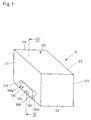
- the cuboid packaging 10 shown in FIGS. 1 and 2 for individual pieces combined to form a shipping and sales unit consists of a lower part 20 receiving the individual pieces in the form of a tray and of an upper part 120 in the form of an outer packaging which overlaps the lower part 20.
- the lower part 20 is formed by a rectangular base plate 25, two longitudinal side walls 21, 23 and two narrow side walls 22, 24.
- This lower part 20 can be produced as a one-piece molded body from plastics or other suitable materials; It is also possible to manufacture the lower part 20 using the deep-drawing process.
- the material used for the manufacture of the lower part 20 should be chosen so that the lower part 20 has sufficient inherent rigidity and stability.
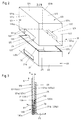
- the lower part 20 consists of a folding blank 220 made of cardboard, cardboard or other suitable materials, the longitudinal side walls 21, 23 via folding lines 26, 27 and the narrow side walls 22, 24 via folding lines 28, 29 are attached to the blanks forming the base plate 25 of the lower part 20.
- the longitudinal side walls 21, 23 and the narrow side walls 22, 24 have the same heights.
- the longitudinal side wall 21 carries a flap 21 ′ which is connected to the longitudinal side wall 21 via a fold line 21 ′′.
- the two longitudinal side walls 21, 23 are connected to the narrow side wall 22 via fold lines 22 ', 22''.
- the narrow side wall 24 is folded onto the longitudinal side wall 23 by means of a fold line 24 '.
- the base plate 25 of the lower part 20, which is open at the top, is formed by individual cut parts in order to obtain a folding box with a folding bottom, wherein the lower part 20 can also be designed as a plug-in box (FIG. 4).
- the upper part 120 of the packaging 10 is also formed by a rectangular folding blank 320 (FIG. 5) and, in addition to an upper cover plate 125, has two longitudinal side walls 121, 123 and two narrow side walls 122, 124, the dimensions and the shape of the cover plate 125 being that of the base plate 25 of the lower part 20 corresponds so that the upper part 120 can be pushed onto the lower part 20 (FIGS. 1 and 2).
- the longitudinal edges of the longitudinal side walls 121, 123 of the upper part 120 are designated by 121a, 123a, the side inner wall surfaces of these two side walls by 121b, 123b and the side outer wall surfaces of these side walls by 121c, 123c.
- the side inner wall surfaces of the longitudinal side walls 21, 23 of the lower part 20, which correspond to the longitudinal side walls 121, 123 of the upper part 120 or are opposite to them, are designated by 21b, 23b (FIG. 2).
- tabs 130 are held in the center, which consist of approximately rectangular or square blanks and of the same material from which the upper part 120 is also made. These tabs protruding from the longitudinal edges 121a, 123a of the longitudinal side walls 121, 123 of the upper part 120 with a tab section 130b are held with their other tab section 130a in the respective longitudinal side wall 121 and 123 of the top part 120 by means of two separating perforations indicated at 132 in the folding blank 320, whereas this is the case free tab end 134 opposite end 134a is connected to the longitudinal side wall 121 or 123 via a fold line 136.
- the tab 130 on the longitudinal side wall 121 is designed in accordance with that tab 130 which is held in the longitudinal side wall 123 of the upper part 120.
- the two flap sections 130a, 130b are connected via a fold line 133, this fold line 133 extending in the region of the longitudinal edge 121a of the long side wall 121, so that the flap section 130b can be folded around the fold line 133 onto the side inner wall surface 121b of the long side wall 121 (FIG. 3 ).
- Each flap 130 is provided with a handle recess 135 in the center and lying in the area of the fold line 133, which is designed as a circular opening in the flap 130, so that after the flap section 130b has been folded onto the side inner wall surface 121b of the longitudinal side wall 121, a semi-circular handle recess results ( 2 and 5).
- the two tabs 130 in the longitudinal side walls 121, 123 are arranged or formed in the center and congruently.
- the longitudinal side wall 121 is connected to the narrow side wall 122 via a fold line 121 ', which carries at its free end a tab 126 which is connected to the narrow side wall 122 via a fold line 122'.
- This flap 126 of the folding blank 320 and also the flap 21 'of the folding blank 220 serve to connect the free ends of the folding blanks 220; 320 in order to form the lower part 20 and the upper part 120.
- These tabs 126 and 21 ' are provided with an adhesive application in order to obtain a firm connection after the folding blanks 220; 320 have been folded accordingly.
- the longitudinal side wall 121 is connected to the narrow side wall 124 via a fold line 121 ′′, which in turn is connected to the longitudinal side wall 123 via a fold line 123 ′.
- the folding blank 320 for forming the cover plate 125 of the upper part 120 being designed as a folded bottom box or as a plug-in bottom box, whereby
- the lower part 20 and the upper part 120 can also be provided with differently designed closure flaps in order to form the base plate 25 and the cover plate 125.
- the upper part 120 or its folding blank 220 is made of cardboard, cardboard or another suitable, preferably foldable, material.
- the height of the longitudinal side walls 121, 123 and the narrow side walls 122, 124 of the upper part 120 preferably corresponds to the height of the long side walls 21, 23 and the narrow side walls 22, 24 of the lower part 20, so that when the upper part 120 is placed on the lower part 20, this has its bottom edges in the area of the base plate 25 of the lower part 20 comes to rest (Fig.1).
- the tabs 130 are provided on two opposite side walls, here on the longitudinal side walls 121, 123.
- the longitudinal side walls 121, 123 carry more than one tab 130.
- the number and arrangement of the tabs 130 will depend in each case on the size of the packaging 10.
- the packaging 10 need not be cuboid.
- the packaging 10 can also have other geometric shapes. Even packaging with sloping side walls can be produced in the same way, can be formed and provided with a snap or snap lock.
- the lower part 20 is provided on each of the longitudinal side walls 21, 23 of the upper part 120 that supports the tab 130, or in each case with a stop edge 50, the number the stop edges 50 corresponds to the number of tabs 130.
- the tab 130 is supported with its tab longitudinal edge 131 formed at the free tab end 134, the width, ie the height of the inside tab portion 131b, of each tab 130 corresponding to the distance of the stop edge 150 from the base plate 25 of the lower part 20 (Fig.3).
- each tab 130 bears against the side inner wall surface 121b of the longitudinal side wall 121, in such a way that the longitudinal tab edge 131 engages under the stop edge 50 which emerges from the longitudinal side wall 21 of the lower part 20 or is formed therein that it is not possible to pull off the upper part 120 from the lower part 20 in the direction of the arrow X (FIG. 3).
- the stop edge 50 When the upper part 120 is lifted, the forward movement of the tab section 130b is inhibited by the stop edge 50.
- a peel or lifting the upper part 120 from the lower part 20 is only possible if the tabs 130 on both sides of the packaging 10 are bent outwards in the direction of the arrow X1 with the aid of the handle recesses 135, the separating perforations 132 in the longitudinal side walls of the upper part 120 being destroyed, so that the flaps 130 can be bent outwards by means of the fold lines 136, the two flap sections 130a, 130b then lying against one another for opening.
- the stop edge 50 consists of a strip-shaped blank 60, which is attached to the outer wall surface of each longitudinal side wall 21 or 23 of the lower part 20, in each case on the longitudinal side walls 21, 23 of the lower part 20, which are connected to the Corresponding tabs 130 carrying longitudinal side walls 121, 123 of the upper part 120, these longitudinal side walls 121, 123 carrying the tabs 130.
- This strip-shaped and 60 forming the stop edge 50 consists of the material of the lower part 20 and / or the upper part 120 and is by means of an adhesive connection, a heat seal or Welded connection attached to the long side wall.
- the strip-shaped blank preferably consists of cardboard, cardboard or another suitable material and has a thickness that corresponds to the thickness of the material of the upper part 120 or the flap 130.
- the longitudinal side wall 21 of the lower part 20 corresponding to the longitudinal side wall 121 of the upper part 120 carrying the tab 130 is provided with a window-like opening or punch-out corresponding to the length of the tab 130 70 provided by a lower longitudinal edge 71, an upper longitudinal edge 73 and two side edges 72,74 is limited.
- the upper longitudinal edge 73 of the window-like opening 70 forms the stop edge 50 (FIGS. 3 and 4).
- This window-like opening 70 is by means of a blank 80 made of cardboard, cardboard or the like. covered, which is fastened to the side inner wall surface 21b of the longitudinal side wall 21 of the lower part 20 by means of an adhesive connection 75.
- This blank 80 which closes the window-like opening 70 to the interior of the lower part 20, can be fastened as an independent blank by means of the adhesive connection to the side inside wall surface of the longitudinal side wall having the window-like opening.
- the blank 80, which covers the window-like opening 70 is folded onto the longitudinal side wall 21 or 23 carrying the window-like opening 70, so that the blank 80 is an integral part of the folding blank 220 from which the lower part 20 is formed.
- the two blanks 80 are connected to the longitudinal side walls 21, 23 via fold lines 81.
- the dimensions of these blanks 80 correspond to the dimensions of the two longitudinal side walls 21, 23 of the lower part 20 or its folding blank 220 (FIG. 5). After the blanks 80 have been folded onto the two longitudinal side walls 21, 23, the blanks 80 are attached to these longitudinal side walls by means of the adhesive connection 75.
- the corresponding adhesive surfaces are indicated in FIG. 4 at 75 'and are arranged above the window-like opening 70. The height of each window-like opening 70 is smaller than the height of the blank 80 (FIG. 3).
- the distance A between the longitudinal side wall 121 of the upper part 120 and the longitudinal side wall 21 of the lower part 20 corresponding to this longitudinal side wall is dimensioned such that even with a fixed one If the tab portion 130b of the tab 130 bears against the inner wall surface of the longitudinal side wall 121 of the upper part 120, this cannot be pulled off the lower part 20 and the locking formed by the stop edge 50 and the tab 130 is not released.
- the stop edge 50 can also be formed by embossing or deep embossing from the material of the longitudinal side wall 21 or 23 of the lower part 20, it being essential that from the plane of the side outer wall surface of the longitudinal side wall 21 or 23 of the lower part 20 the stop edge 50 is formed outstanding.
- the complete package 10 thus consists of the lower part 20 and the upper part 120.
- the upper part 120 has a cover plate glued in accordance with ECMA code A 510, any other possibility of closure being possible.
- a tab 130 is provided on each side on the lower longitudinal edge of the upper part 120, specifically in the middle of the longitudinal edge. After the upper part 120 has been erected, the tabs 130 are inserted with their tab portions 130b inwards and the entire upper part is placed on the lower part 20 filled with products. After being completely slipped over to the base plate 25 of the lower part 20, the tabs 130 snap into the window-like openings or cutouts 70 in the side walls of the lower part 20 or the tabs are supported on the formed stop edges 50.
- the inside tab sections 130b ie the tabs 130, can be glued off be solved with the lower part 20.
- the crescent-shaped recesses 135 in the area of the break-open tabs provided with separating perforation support the opening of the packaging.
- a simple handgrip opens the product in order to place it on the shelf.
- the closure provided and designed for the packaging 10 also serves as an anti-theft device and as a tamper-evident closure.
- the lower part 20 also has a base plate bonded in accordance with ECMA code A 510, any other closure configuration also being possible.
- This lower part 20 has in the form of blanks 80 elongated long sides, which are grooved in the middle or provided with fold lines. These blanks 80, i.e. the upper long sides are folded down and glued to the long side walls of the lower part 20. The gluing is above the window-like opening 70. This is the only way to achieve a desired, firm heel, i.e. Stop edge 50 is reached in the opening area 70, in which the tabs 130 of the upper part 120 snap into place.
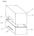
- the cuboid packaging 410 shown in FIGS. 7 and 8 of a further embodiment for individual pieces combined to form a shipping and sales unit consists of a lower part 420 receiving the individual pieces in the form of a tray and an upper part 520 in the form of an outer packaging which overlaps the lower part 420 .
- the lower part 420 is formed by a rectangular base plate 425, two longitudinal side walls 421, 423 and two narrow side walls 422, 424.
- This lower part 420 can be produced as a one-piece molded body from plastics or other suitable materials; also it is possible to manufacture the lower part 420 using the deep-drawing process.
- the material used for the production of the lower part 420 should be chosen so that the lower part 420 has sufficient inherent rigidity and stability.
- the lower part 420 consists of a folding blank 720 made of cardboard, cardboard or other suitable materials, the longitudinal side walls 421, 423 via folding lines 426, 427 and the narrow side walls 422, 424 via folding lines 428, 429 on the bottom plate 425 of the lower part 420 forming blanks are attached.
- the long side walls 421, 423 and the narrow side walls 422, 424 have the same heights.
- the longitudinal side wall 421 carries a flap 421 ′ which is connected to the longitudinal side wall 421 via a fold line 421 ′′.
- the two longitudinal side walls 421, 423 are connected to the narrow side wall 422 via fold lines 422 ', 422' '.
- the narrow side wall 424 is folded onto the longitudinal side wall 423 by means of a fold line 424 '.
- the bottom plate 425 of the lower part 420 which is open at the top, is formed by individual cut parts in order to obtain a folding box with a folding bottom, wherein the lower part 420 can also be designed as a plug-in box (FIG. 11).
- the upper part 520 of the packaging 410 is likewise formed by a rectangular folding blank 620 (FIG. 10) and, in addition to an upper cover plate 525, has two longitudinal side walls 521, 523 and two narrow side walls 522, 524, the dimensions and the shape of the cover plate 525 being that of the base plate 425 of the lower part 420 corresponds, so that the upper part 520 on the lower part 420 can be pushed on (FIGS. 7 and 8).
- the longitudinal edges of the longitudinal side walls 521, 523 of the upper part 520 are denoted by 521, 523a, the side inner wall surfaces of these two side walls by 521b, 523b and the side outer wall surfaces of these side walls by 521c, 523c.
- the side inner wall surfaces of the longitudinal side walls 421, 423 of the lower part 420, which correspond to the longitudinal side walls 521, 523 of the upper part 520 or are opposite to them, are designated by 421b, 423b (FIG. 8).
- tabs 530 are held in the center, which consist of approximately rectangular or square blanks and of the same material as the upper part 520.
- These tabs projecting from the longitudinal edges 521a, 523a of the longitudinal side walls 521, 523 of the upper part 520 with a tab section 430b are held with their other tab section 530a in the respective longitudinal side wall 521 and 523 of the top part 520 by means of two separating perforations indicated at 532 in the folding blank 620, whereas this is the case Free tab end 534 opposite end 534a is connected via a fold line 536 to the longitudinal side wall 521 or 523.
- the tab 530 on the longitudinal side wall 521 is designed corresponding to that tab 530 which is held in the longitudinal side wall 523 of the upper part 520.
- the two flap sections 530a, 530b are connected via a fold line 533, this fold line 533 running in the region of the longitudinal edge 521a of the longitudinal side wall 521, so that the flap section 530b can be folded around the fold line 533 onto the side inner wall surface 521b of the longitudinal side wall 521 (FIG. 9 ).
- Each flap 530 is provided in the center and lying in the region of the folding line 533 with a handle recess 535 which acts as circular opening is formed in the tab 530, so that after the tab section 530b is folded onto the side inner wall surface 521b of the longitudinal side wall 521, a semicircular handle recess results (FIGS. 8 and 10).
- the two tabs 530 are arranged or formed in the center and congruent in the longitudinal side walls 521, 523.
- the longitudinal side wall 521 is connected to the narrow side wall 522 via a fold line 521 ', which carries at its free end a tab 526 which is connected to the narrow side wall 522 via a fold line 522'.
- This flap 526 of the folding blank 620 and also the flap 421 'of the folding blank 720 serve to connect the free ends of the folding blanks 620; 720 in order to form the lower part 420 and the upper part 520.
- These tabs 526 and 421 ' are provided with an adhesive application in order to obtain a firm connection after the folding blanks 620; 720 have been folded accordingly.
- the longitudinal side wall 521 is connected to the narrow side wall 524 via a folding line 521 ′′, which in turn is connected to the longitudinal side wall 523 via a folding line 523 ′.
- the parts forming the cover plate 525 are folded, the folding blank 620 for forming the cover plate 425 of the upper part 520 being designed as a folded bottom box or as a plug-in box, the The lower part 420 and the upper part 520 also have different designs Closure flaps can be provided to form the bottom plate 425 and the top plate 525.
- the upper part 520 or its folding blank 620 is made of cardboard, cardboard or another suitable, preferably foldable material.
- the height of the longitudinal side walls 521, 523 and the narrow side walls 522, 524 of the upper part 520 preferably corresponds to the height of the long side walls 421, 423 and the narrow side walls 422, 424 of the lower part 420, so that when the upper part 520 is placed on the lower part 420, this has its bottom edges in the region of the base plate 425 of the lower part 420 comes to rest (Fig. 7).
- the tabs 530 are provided on two opposite side walls, here on the longitudinal side walls 521, 523. However, there is also the possibility of providing additional tabs on the narrow side walls 522, 524. Each longitudinal side wall 521, 523 can also carry more than one tab 530. The number and arrangement of the tabs 530 will depend in each case on the size of the packaging 410.
- the packaging 410 need not be cuboid.
- Package 410 may also have other geometric shapes. Even packaging with sloping side walls can be produced in the same way, can be formed and provided with a snap or snap lock.
- the lower part 420 is in each length corresponding to the long side wall 521, 523 of the upper part 520 carrying the flap 530, with a window-like opening or punching 470 with a length corresponding to the length of the flap 530 or the flap section 530b Mistake.
- This punched-out 470 is divided by means of a central web 470a into two window sections 470a ′, 470a ′′, which are preferably of equal size and the same size and dimensions, and the upper stop edges 470b, 470b ′. point.
- each punching 570 causes a slight curvature in the central area of the tab section 530b of the tab 530, so that the two outer, horizontal edge areas 530c, 530c 'align with the upper edges 470b , 470b 'of the two window sections 470a', 470a '', the height A1 of the tab section 530b being the distance A of the upper edges 470b, 470b 'of the two window sections 470a', 470a '' from the peripheral edge or the outer edges 521a, 523a of the lower part 420 corresponds (FIGS. 10 and 11).
- the tab 530 is supported on the stop edges 470b, 470b 'with its lower edge regions 530c, 530c', the width, ie the height, of the inside tab section 531b of each tab 530 the distance of the stop edges 470b, 470b 'from the base plate 425 of the lower part 420 corresponds (FIG. 9).
- the tab portion 530b of each tab 530 bears against the side inner wall surface 521b of the longitudinal side wall 521, in such a way that the outer tab edge areas 530c, 530c 'from the longitudinal.
- the upper part 520 can only be pulled off or lifted off from the lower part 420 if, with the aid of the handle recesses 535 on both sides of the packaging 410, the tabs 530 are bent outwards in the direction of the arrow X2, the separating perforations 532 in the longitudinal side walls of the upper part 520 being destroyed so that the flap 530 can be bent outwards by means of the folding lines 536, the two flap sections 530a, 530b then lying against one another for opening (FIG. 9).
- the stop edges 470b, 470b ' can also be formed by embossing or deep embossing from the material of the longitudinal side wall 421 or 423 of the lower part 420, it being essential that from the plane of the side outer wall surface of the longitudinal side wall 421 or 423 of the lower part 420, the stop edges are protruding.
- the complete packaging 410 thus consists of the lower part 420 and the upper part 520.
- the upper part 520 has a cover plate glued in accordance with ECMA code A 610, wherein any other possibility of closure is also possible.
- a tab 530 is provided on each side on the lower longitudinal edge of the upper part 520, specifically in the middle of the longitudinal edge. After the upper part 520 has been erected, the tabs 530 are inserted with their tab sections 530b inwards and the entire upper part is placed on the lower part 420 filled with products.
- the tabs 530 After completely slipping over to the base plate 425 of the lower part 420, the tabs 530 snap into the window-like openings or punched-out areas 470 in the side walls of the lower part 420 or the tabs are supported on the formed stop edges 470b, 470b '. Due to the separating perforation 532 arranged on both sides of the tab section 530a arranged in each side wall of the upper part 520, the inside tab sections 530b, ie the tabs 530, can be released. Support for opening the packaging is provided by the crescent-shaped handle recesses 535 formed in the area of the break-open perforations provided with separating perforations. A simple handgrip opens the product in order to place it on the shelf.
- the closure provided and designed for the packaging 410 also serves as an anti-theft protection and as a tamper-evident closure.
- the lower part 420 also has a base plate adhered to ECMA code A 610, and any other closure configuration is also possible.
- each window-like opening or cut-out 470 has a conical shape that tapers to the peripheral edge of the lower part 420 or an oval or another geometric shape.
- the tabs 530 and the window-like openings or punch-outs 470 corresponding to them are provided on the narrow sides of the packaging, since in these areas the packaging 410 has the highest inherent rigidity in the region of its side walls.
- the packaging has on each side wall a plurality of tabs 530 arranged one behind the other with the window-like openings or punch-outs 470 corresponding to them. This configuration is always advantageous if the packaging has larger dimensions.
- the packaging can also have at least one tab 530 on each of its four side walls with a window-like opening or punching 470 corresponding to it.
Landscapes
- Engineering & Computer Science (AREA)
- Mechanical Engineering (AREA)
- Cartons (AREA)
Applications Claiming Priority (4)
| Application Number | Priority Date | Filing Date | Title |
|---|---|---|---|
| DE9207105U DE9207105U1 (de) | 1992-05-26 | 1992-05-26 | Verpackung |
| DE9207105U | 1992-05-26 | ||
| DE9214668U | 1992-10-29 | ||
| DE9214668U DE9214668U1 (de) | 1992-10-29 | 1992-10-29 | Verpackung |
Publications (3)
| Publication Number | Publication Date |
|---|---|
| EP0571711A2 true EP0571711A2 (fr) | 1993-12-01 |
| EP0571711A3 EP0571711A3 (fr) | 1994-03-23 |
| EP0571711B1 EP0571711B1 (fr) | 1996-05-15 |
Family
ID=25959541
Family Applications (1)
| Application Number | Title | Priority Date | Filing Date |
|---|---|---|---|
| EP93101979A Expired - Lifetime EP0571711B1 (fr) | 1992-05-26 | 1993-02-09 | Boîte pliante avec couvercle emboîtable |
Country Status (2)
| Country | Link |
|---|---|
| EP (1) | EP0571711B1 (fr) |
| DE (1) | DE59302567D1 (fr) |
Cited By (17)
| Publication number | Priority date | Publication date | Assignee | Title |
|---|---|---|---|---|
| WO1996017793A1 (fr) * | 1994-12-08 | 1996-06-13 | Csr Limited | Emballage de protection |
| AU690711B2 (en) * | 1994-12-08 | 1998-04-30 | Csr Limited | Improvements in and relating to packaging |
| GB2332421A (en) * | 1997-12-17 | 1999-06-23 | Smurfit Corrugated Res Ltd | Display packaging |
| AU711215B3 (en) * | 1999-05-26 | 1999-10-07 | Carter Holt Harvey Limited | Pack |
| DE10033338A1 (de) * | 2000-07-08 | 2001-09-06 | Henkel Kgaa | Umverpackung für Produktaufnahmebehältnisse |
| DE102007037405A1 (de) | 2007-08-08 | 2009-02-12 | Beiersdorf Ag | Zweiteilige Umverpackung für schwere Güter |
| EP2308762A1 (fr) | 2009-10-09 | 2011-04-13 | The Procter & Gamble Company | Plateau et emballage de hotte |
| ES2395441A1 (es) * | 2011-04-07 | 2013-02-12 | Cartonajes International, S.L., Sociedad Unipersonal | Caja expositora de dos piezas con medios de unión |
| CN109703862A (zh) * | 2019-03-11 | 2019-05-03 | 深圳市尚普瑞科技有限公司 | 包装盒 |
| IT201900015399A1 (it) * | 2019-09-02 | 2021-03-02 | Igb Srl | Confezione a prova di bambino e procedimento per la realizzazione della stessa, metodo di chiusura ed apertura di detta confezione |
| IT201900015410A1 (it) * | 2019-09-02 | 2021-03-02 | Igb Srl | Confezione a prova di bambino e procedimento per la realizzazione della stessa, metodo di chiusura ed apertura di detta confezione |
| WO2021044270A1 (fr) * | 2019-09-02 | 2021-03-11 | I.G.B. S.R.L. | Système d'accouplement, procédé de fabrication dudit système d'accouplement, récipient à sécurité-enfants et emballage à sécurité-enfants |
| US11732216B2 (en) | 2020-06-10 | 2023-08-22 | The Procter & Gamble Company | Laundry care or dish care composition comprising a poly alpha-1,6-glucan derivative |
| US11794947B2 (en) | 2020-07-09 | 2023-10-24 | The Procter & Gamble Company | Cardboard support element |
| US11932468B2 (en) | 2020-05-08 | 2024-03-19 | The Procter & Gamble Company | Detergent product container with lock |
| US11965147B2 (en) | 2020-06-10 | 2024-04-23 | The Procter & Gamble Company | Laundry care or dish care composition comprising a poly alpha-1,6-glucan derivative |
| US12006489B2 (en) | 2016-12-16 | 2024-06-11 | The Procter & Gamble Company | Amphiphilic polysaccharide derivatives and compositions comprising same |
Citations (5)
| Publication number | Priority date | Publication date | Assignee | Title |
|---|---|---|---|---|
| DE1212861B (de) * | 1963-04-05 | 1966-03-17 | Rotopack G M B H Verpackungsmi | Stuelpfaltschachtel |
| DE2425694A1 (de) * | 1974-05-28 | 1975-12-11 | 4 P Verpackungen Gmbh | Stuelpdeckelschachtel |
| FR2631608A1 (fr) * | 1988-05-20 | 1989-11-24 | Rochette Cenpa | Caisse d'emballage inviolable |
| DE9011828U1 (de) * | 1990-08-10 | 1990-11-29 | Europa Carton Ag, 2000 Hamburg | Verpackung aus faltbarem Material |
| DE9105890U1 (de) * | 1990-05-12 | 1991-08-01 | Beiersdorf Ag, 20253 Hamburg | Verpackung |
-
1993
- 1993-02-09 EP EP93101979A patent/EP0571711B1/fr not_active Expired - Lifetime
- 1993-02-09 DE DE59302567T patent/DE59302567D1/de not_active Expired - Lifetime
Patent Citations (5)
| Publication number | Priority date | Publication date | Assignee | Title |
|---|---|---|---|---|
| DE1212861B (de) * | 1963-04-05 | 1966-03-17 | Rotopack G M B H Verpackungsmi | Stuelpfaltschachtel |
| DE2425694A1 (de) * | 1974-05-28 | 1975-12-11 | 4 P Verpackungen Gmbh | Stuelpdeckelschachtel |
| FR2631608A1 (fr) * | 1988-05-20 | 1989-11-24 | Rochette Cenpa | Caisse d'emballage inviolable |
| DE9105890U1 (de) * | 1990-05-12 | 1991-08-01 | Beiersdorf Ag, 20253 Hamburg | Verpackung |
| DE9011828U1 (de) * | 1990-08-10 | 1990-11-29 | Europa Carton Ag, 2000 Hamburg | Verpackung aus faltbarem Material |
Cited By (27)
| Publication number | Priority date | Publication date | Assignee | Title |
|---|---|---|---|---|
| WO1996017793A1 (fr) * | 1994-12-08 | 1996-06-13 | Csr Limited | Emballage de protection |
| AU690711B2 (en) * | 1994-12-08 | 1998-04-30 | Csr Limited | Improvements in and relating to packaging |
| GB2332421A (en) * | 1997-12-17 | 1999-06-23 | Smurfit Corrugated Res Ltd | Display packaging |
| GB2332421B (en) * | 1997-12-17 | 2002-02-13 | Smurfit Corrugated Ltd | Improvements in or relating to display packaging |
| AU711215B3 (en) * | 1999-05-26 | 1999-10-07 | Carter Holt Harvey Limited | Pack |
| WO2000073157A1 (fr) * | 1999-05-26 | 2000-12-07 | Carter Holt Harvey Limited | Ensembles recipient/encadrement |
| AU744208B2 (en) * | 1999-05-26 | 2002-02-21 | Carter Holt Harvey Limited | Container/surround assemblies |
| DE10033338A1 (de) * | 2000-07-08 | 2001-09-06 | Henkel Kgaa | Umverpackung für Produktaufnahmebehältnisse |
| DE102007037405A1 (de) | 2007-08-08 | 2009-02-12 | Beiersdorf Ag | Zweiteilige Umverpackung für schwere Güter |
| EP2960170A1 (fr) | 2009-10-09 | 2015-12-30 | The Procter and Gamble Company | Plateau et emballage de hotte |
| EP2308762A1 (fr) | 2009-10-09 | 2011-04-13 | The Procter & Gamble Company | Plateau et emballage de hotte |
| WO2011044403A1 (fr) | 2009-10-09 | 2011-04-14 | The Procter & Gamble Company | Emballage à plateau et couvercle |
| ES2395441A1 (es) * | 2011-04-07 | 2013-02-12 | Cartonajes International, S.L., Sociedad Unipersonal | Caja expositora de dos piezas con medios de unión |
| US12006489B2 (en) | 2016-12-16 | 2024-06-11 | The Procter & Gamble Company | Amphiphilic polysaccharide derivatives and compositions comprising same |
| CN109703862B (zh) * | 2019-03-11 | 2023-12-19 | 深圳市尚普瑞科技有限公司 | 包装盒 |
| CN109703862A (zh) * | 2019-03-11 | 2019-05-03 | 深圳市尚普瑞科技有限公司 | 包装盒 |
| IT201900015399A1 (it) * | 2019-09-02 | 2021-03-02 | Igb Srl | Confezione a prova di bambino e procedimento per la realizzazione della stessa, metodo di chiusura ed apertura di detta confezione |
| WO2021044267A1 (fr) * | 2019-09-02 | 2021-03-11 | I.G.B. S.R.L. | Emballage à l'épreuve des enfants et son procédé de fabrication, procédé de fermeture et d'ouverture dudit emballage |
| WO2021044270A1 (fr) * | 2019-09-02 | 2021-03-11 | I.G.B. S.R.L. | Système d'accouplement, procédé de fabrication dudit système d'accouplement, récipient à sécurité-enfants et emballage à sécurité-enfants |
| US20220332480A1 (en) * | 2019-09-02 | 2022-10-20 | I.G.B. S.R.L. | Coupling system, process of making the same, child-proof container and child-proof package |
| WO2021044268A1 (fr) * | 2019-09-02 | 2021-03-11 | I.G.B. S.R.L. | Emballage à l'épreuve des enfants et son procédé de fabrication, procédé de fermeture et d'ouverture dudit emballage |
| US11897673B2 (en) | 2019-09-02 | 2024-02-13 | I.G.B. S.R.L. | Child-proof package and process of making the same, method for closing and opening said package |
| IT201900015410A1 (it) * | 2019-09-02 | 2021-03-02 | Igb Srl | Confezione a prova di bambino e procedimento per la realizzazione della stessa, metodo di chiusura ed apertura di detta confezione |
| US11932468B2 (en) | 2020-05-08 | 2024-03-19 | The Procter & Gamble Company | Detergent product container with lock |
| US11732216B2 (en) | 2020-06-10 | 2023-08-22 | The Procter & Gamble Company | Laundry care or dish care composition comprising a poly alpha-1,6-glucan derivative |
| US11965147B2 (en) | 2020-06-10 | 2024-04-23 | The Procter & Gamble Company | Laundry care or dish care composition comprising a poly alpha-1,6-glucan derivative |
| US11794947B2 (en) | 2020-07-09 | 2023-10-24 | The Procter & Gamble Company | Cardboard support element |
Also Published As
| Publication number | Publication date |
|---|---|
| EP0571711A3 (fr) | 1994-03-23 |
| DE59302567D1 (de) | 1996-06-20 |
| EP0571711B1 (fr) | 1996-05-15 |
Similar Documents
| Publication | Publication Date | Title |
|---|---|---|
| EP0571711B1 (fr) | Boîte pliante avec couvercle emboîtable | |
| EP1637460B1 (fr) | Conditionnement | |
| EP0341549B1 (fr) | Récipient et procédure de remplissage et emploi | |
| DD285321A5 (de) | Verpackungsbehaelter und verfahren zum fuellen sowie inbetriebnehmen des behaelters | |
| EP0456896B1 (fr) | Emballage | |
| US6651873B2 (en) | Container with bag cuff grab means | |
| DE9105890U1 (de) | Verpackung | |
| DE69211219T2 (de) | Öffnungskonstruktion für keilförmige Torteschachtel | |
| EP0409366A2 (fr) | Emballage parallèlipipédique en matériel pliant | |
| EP0784013B1 (fr) | Boíte d'emballage cartonnée | |
| EP0524400A1 (fr) | Emballage pour petits objets, du type articles courts rigides ou similaires | |
| DE4214040C1 (en) | Vending pack with pendant support and resealable closure - is made from sheet of folded card with double layer support flap | |
| DE2315127A1 (de) | Verpackung | |
| DE9207105U1 (de) | Verpackung | |
| DE2904055C2 (de) | Sammelverpackung mit Verwendungsmöglichkeit als Verkaufspackung | |
| DE8522798U1 (de) | Zuschnitt für einen Verpackungskarton mit Präsentationsfenster und Traggriff | |
| DE9214668U1 (de) | Verpackung | |
| DE602004000602T2 (de) | Verpackung mit abreissbarer Laschen, die zum Greifen des Halses einer Phiole vorgesehen sind | |
| DE4217111A1 (de) | Faltschachtel | |
| EP0157338A2 (fr) | Gaine d'emballage en carton pour plusieurs objets | |
| DE8605398U1 (de) | Verpackung aus trayartigem Unterteil und haubenartiger Abdeckung, insbesondere für Flaschen | |
| EP1110872A1 (fr) | Emballage et flan pour l'emballage, le transport et la distribution d'articles | |
| DE4320100C2 (de) | Versandverpackung | |
| DE4447026A1 (de) | Schachtel, insbesondere Faltschachtel, vorzugsweise für Schuhe | |
| EP2239209B1 (fr) | Dispositif de rembourrage destiné à servir de protection de transport ainsi qu'élément de rembourrage en tant que composant d'une protection de transport |
Legal Events
| Date | Code | Title | Description |
|---|---|---|---|
| PUAI | Public reference made under article 153(3) epc to a published international application that has entered the european phase |
Free format text: ORIGINAL CODE: 0009012 |
|
| AK | Designated contracting states |
Kind code of ref document: A2 Designated state(s): DE ES FR IT NL |
|
| PUAL | Search report despatched |
Free format text: ORIGINAL CODE: 0009013 |
|
| AK | Designated contracting states |
Kind code of ref document: A3 Designated state(s): DE ES FR IT NL |
|
| 17P | Request for examination filed |
Effective date: 19940603 |
|
| 17Q | First examination report despatched |
Effective date: 19950726 |
|
| ITF | It: translation for a ep patent filed | ||
| GRAA | (expected) grant |
Free format text: ORIGINAL CODE: 0009210 |
|
| AK | Designated contracting states |
Kind code of ref document: B1 Designated state(s): DE ES FR IT NL |
|
| PG25 | Lapsed in a contracting state [announced via postgrant information from national office to epo] |
Ref country code: NL Free format text: LAPSE BECAUSE OF FAILURE TO SUBMIT A TRANSLATION OF THE DESCRIPTION OR TO PAY THE FEE WITHIN THE PRESCRIBED TIME-LIMIT Effective date: 19960515 Ref country code: ES Free format text: THE PATENT HAS BEEN ANNULLED BY A DECISION OF A NATIONAL AUTHORITY Effective date: 19960515 |
|
| ET | Fr: translation filed | ||
| REF | Corresponds to: |
Ref document number: 59302567 Country of ref document: DE Date of ref document: 19960620 |
|
| NLV1 | Nl: lapsed or annulled due to failure to fulfill the requirements of art. 29p and 29m of the patents act | ||
| PLBE | No opposition filed within time limit |
Free format text: ORIGINAL CODE: 0009261 |
|
| STAA | Information on the status of an ep patent application or granted ep patent |
Free format text: STATUS: NO OPPOSITION FILED WITHIN TIME LIMIT |
|
| 26N | No opposition filed | ||
| PGFP | Annual fee paid to national office [announced via postgrant information from national office to epo] |
Ref country code: IT Payment date: 20090221 Year of fee payment: 17 |
|
| PGFP | Annual fee paid to national office [announced via postgrant information from national office to epo] |
Ref country code: FR Payment date: 20090220 Year of fee payment: 17 |
|
| REG | Reference to a national code |
Ref country code: FR Ref legal event code: ST Effective date: 20101029 |
|
| PG25 | Lapsed in a contracting state [announced via postgrant information from national office to epo] |
Ref country code: FR Free format text: LAPSE BECAUSE OF NON-PAYMENT OF DUE FEES Effective date: 20100301 |
|
| PG25 | Lapsed in a contracting state [announced via postgrant information from national office to epo] |
Ref country code: IT Free format text: LAPSE BECAUSE OF NON-PAYMENT OF DUE FEES Effective date: 20100209 |
|
| PGFP | Annual fee paid to national office [announced via postgrant information from national office to epo] |
Ref country code: DE Payment date: 20120424 Year of fee payment: 20 |
|
| REG | Reference to a national code |
Ref country code: DE Ref legal event code: R071 Ref document number: 59302567 Country of ref document: DE |
|
| REG | Reference to a national code |
Ref country code: DE Ref legal event code: R082 Ref document number: 59302567 Country of ref document: DE Representative=s name: KEIL & SCHAAFHAUSEN PATENT- UND RECHTSANWAELTE, DE Effective date: 20130221 Ref country code: DE Ref legal event code: R081 Ref document number: 59302567 Country of ref document: DE Owner name: DS SMITH PACKAGING DEUTSCHLAND STIFTUNG & CO. , DE Free format text: FORMER OWNER: SCA PACKAGING DEUTSCHLAND STIFTUNG & CO. KG, 36043 FULDA, DE Effective date: 20130221 |
|
| PG25 | Lapsed in a contracting state [announced via postgrant information from national office to epo] |
Ref country code: DE Free format text: LAPSE BECAUSE OF EXPIRATION OF PROTECTION Effective date: 20130212 |