EP0571017B1 - Procédé de filtrage pour un système rayons X et agencement pour réaliser ledit procédé de filtrage - Google Patents
Procédé de filtrage pour un système rayons X et agencement pour réaliser ledit procédé de filtrage Download PDFInfo
- Publication number
- EP0571017B1 EP0571017B1 EP93201335A EP93201335A EP0571017B1 EP 0571017 B1 EP0571017 B1 EP 0571017B1 EP 93201335 A EP93201335 A EP 93201335A EP 93201335 A EP93201335 A EP 93201335A EP 0571017 B1 EP0571017 B1 EP 0571017B1
- Authority
- EP
- European Patent Office
- Prior art keywords
- filter
- ray
- energy
- quanta
- measurement
- Prior art date
- Legal status (The legal status is an assumption and is not a legal conclusion. Google has not performed a legal analysis and makes no representation as to the accuracy of the status listed.)
- Expired - Lifetime
Links
Images
Classifications
-
- G—PHYSICS
- G21—NUCLEAR PHYSICS; NUCLEAR ENGINEERING
- G21K—TECHNIQUES FOR HANDLING PARTICLES OR IONISING RADIATION NOT OTHERWISE PROVIDED FOR; IRRADIATION DEVICES; GAMMA RAY OR X-RAY MICROSCOPES
- G21K1/00—Arrangements for handling particles or ionising radiation, e.g. focusing or moderating
- G21K1/10—Scattering devices; Absorbing devices; Ionising radiation filters
Definitions
- the invention relates to a filter method for an X-ray system and an arrangement for carrying out this filter method.
- a filter method for an X-ray system which irradiates an examination area, the X-ray radiation from the examination area being measured by a detector arrangement.
- a first measurement is carried out with a first filter in the beam path between the X-ray emitter and the examination area and a second measurement is carried out with a second filter.
- the two filters have different absorption edges and are dimensioned such that they have the same absorption or transmission for all X-ray quanta outside the energy range between the absorption edges of the two filters. If the result of the two measurements is subtracted from one another, a difference value results which only depends on the spectral components of the polychromatic X-ray emitter which lie within the energy range between the two absorption edges.
- filters made of different materials are placed in the beam path between the X-ray source and the examination area
- a filter is placed in the beam path between the X-ray source and the examination area
- a filter is placed in the beam path placed between the examination area and the detector arrangement, the filter material being the same in both cases.
- the same filter can therefore be used for both measurements.
- the method according to the invention makes it possible to separate the components which have arisen from different interactions with the examination area.
- a first further development of the invention provides that an essentially monochromatic x-ray emitter is used, that the filter material has an absorption edge at a quantum energy which is slightly lower than the energy of the x-ray quanta emitted by the monochromatic x-ray emitter and that the x-ray quanta from the detector arrangement under one An angle is detected that is greater than the angle at which the energy loss of the X-ray quanta by Compton scattering corresponds exactly to the difference between the energy of the X-ray quanta and the quantum energy at which the filter has its absorption edge.
- This method allows the scatter cross section to be determined for elastic (coherent) scatter radiation or also for inelastic (incoherent) scatter radiation.
- an essentially monochromatic x-ray emitter is used, that the filter material has an absorption edge at a quantum energy which is slightly lower than the energy of the x-ray quanta emitted by the monochromatic x-ray emitter, that the x-ray quanta are below the detector arrangement an angle is detected that is smaller than the angle at which the energy loss of the X-ray quanta by Compton scattering corresponds exactly to the difference between the energy of the X-ray quanta and the energy of the X-ray quanta at which the filter material has an absorption edge and that the quantum energy is energy-resolving is measured.
- the components due to Compton and Rayleigh scattering can be suppressed, so that only components remain which are generated by photoelectronic braking radiation. It can be used to determine the content of substances with a low atomic number, e.g. Determine carbon, oxygen or nitrogen).
- Another embodiment of the invention provides that a polychromatic x-ray emitter is used and that the scattered radiation emerging under a certain scattering angle range is measured by the detector arrangement.
- the measured values obtained after subtractive combination of the measurement signals are only determined by X-ray quanta within a certain energy band; the effect of the other X-ray quanta is eliminated by the subtractive combination.
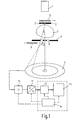
- Fig. 1 denotes an X-ray emitter which emits monochromatic X-ray radiation; the X-ray quanta emitted by the radiator 1 therefore all have essentially the same energy.
- a diaphragm 2 provided with a central bore allows only one needle beam (pencil beam) 3 to pass through the x-ray beam emitted by the x-ray emitter 1.
- the needle beam 3 passes through the central opening in a further diaphragm plate 4.
- the two diaphragm plates 2 and 4 delimit an examination area in the direction perpendicular to the needle beam 3, in which an examination object 7 is located.
- the X-ray quanta in the needle beam 3 interact with the examination object 7 and produce, among other things, elastic and inelastic scattered radiation.
- the scattered radiation which is generated in the examination object 7 between a minimum angle ⁇ 1 and a maximum angle ⁇ 2 can be formed in the aperture 4 through an annular opening 8 which is concentric with the needle beam 3 reach an annular detector 9 therethrough.
- the detector signal is amplified by an integrating amplifier 10 and converted into a digital data word by an analog-digital converter. This data word is proportional to the number of X-ray quanta registered by the annular detector 9 during an integration interval or a measuring time and is independent of the energy of the X-ray quanta.
- the data word can be stored in a memory 12 and further processed in an arithmetic logic unit (ALU 13).
- ALU 13 arithmetic logic unit
- the units 10-13 are controlled by a control unit 14.
- the units 12-14 can be part of a microprocessor.
- a first measurement is carried out first.
- this first measurement there is a filter 5 in the beam path between the monochromatic x-ray emitter 1 and the examination area 7, which has an absorption edge at a quantum energy E k which is slightly lower than the energy of the x-ray emitter emitted by the x-ray emitter 1.
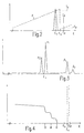
- FIG. 2 shows the energy spectrum (ie the intensity of the X-ray radiation as a function of the energy of the X-ray quanta).
- a line E p and a component E s with lower energy can be seen in the spectrum.
- the line E p is created by elastic scattering, in which the X-ray quanta are known to lose no energy.
- the energy E p is therefore also the energy of the X-ray quanta emitted by the X-ray emitter 1.
- E p is the energy of the X-ray quantum before the scattering process
- E s is the energy of the X-ray quantum
- after the scattering process c is a constant
- ⁇ is the angle that the path of the scattered X-ray quantum includes with the direction of the needle beam 3.
- Equation (1) assumes that the electrons are stationary. In reality, however, the electrons move. This leads to a widening of the Compton line (Compton shift). In this case, equation (1) describes the Energy of the Compton peak. The width of the Compton peak is small for scattering under a small scattering angle.
- the broadening of the component E s compared to the component E p also results from the fact that X-ray quanta can reach the detector ring 9 at different scattering angles. If it is ensured that scattered radiation can only reach the detector arrangement at a defined scattering angle, there is approximately a line for component E s .
- This can be achieved, for example, by using a primary beam with the shape of a cone shell instead of a needle-shaped primary beam and by forming the diaphragm 4 by collimator bodies concentric to the axis of symmetry of the cone shell, as described in DE-OS 40 34 602.
- the filter 5 shown in FIG. 1 consists of a material with an absorption edge at a quantum energy E k which is slightly smaller than the energy of the X-ray quanta emitted by the X-ray emitter but greater than the energy E s of the X-ray quanta influenced by the scattering process.
- E k the course of the transmission of this filter as a function of the energy of the X-ray quanta
- the transmission increases monotonously up to the absorption edge, then jumps to a low value and then rises again.
- the transmission of the filter 5 for the energy of the primary radiation is denoted by T p
- the (larger) transmission of the filter for the energy E s is denoted by T s .
- the analog-digital converter 11 delivers a signal which is proportional to the time integral over the intensity.
- a further measurement is then carried out, in which - as indicated by arrows - the filter 5 is moved out of the beam path and a filter 6 into the beam path between the examination area 7 and the detector arrangement 9.
- the filter 6 must be made of the same material as the filter 5 and can have the same thickness. In the latter case, one could get by with a filter that is above the examination area for one measurement and for the another measurement is arranged below the examination area.
- the filter 6 does not affect the scattered components E p and E s in the same way.
- the component E p is weakened by the filter 6 to the same extent as by the filter 5.
- the component E s is weakened less because T s is greater than T p .
- the measurement time available for this measurement corresponds to the measurement time for the previous measurement.
- the difference between the signals obtained in the measurements can be formed. Since the component E p is damped to the same extent by the filters 5 and 6 in the two measurements, the difference between the measurement signals depends only on the component E s , which is caused by Compton scattering. The difference signal is therefore a measure of the Compton scatter.
- the component E s experiences the same attenuation in both measurements, while the component E p is suppressed more during this second measurement. Therefore, if the difference between the measurement signals in the two measurements is formed, the difference signal is independent of E s and a measure of the elastic scattered radiation.
- the same result can also be achieved if a filter made of the same material and the same thickness is used in the beam path between the examination area 7 and the detector arrangement 9 as the filter 5 and the intensity of the needle beam 3 or the measuring time by a factor of T s / T p increased.
- a modification of the arrangement according to FIG. 1 allows the calculation of the scattering cross section of a volume element for elastic and / or non-elastic scatter radiation.
- a diaphragm arrangement must be arranged between the detector arrangement 9 and the examination area 7, through which the detector arrangement can only "see” a volume element on the needle beam 3 of the examination region 7. (In this case, it is expedient if the object 7 can be displaced relative to the other components of the arrangement - or vice versa - not only perpendicularly to the needle beam 3, but also in the direction of the needle beam 3, so that each volume element within the body 7 is examined if necessary can be).
- a e and A i are factors that are proportional to the scattering cross sections for elastic (Rayleigh) and inelastic (Compton) scattering radiation and I p the intensity in the needle beam 3.
- Equation 5 shows that the cross section A e for the elastic scattered radiation can also be determined without changing the filter thickness, the measuring time or the intensity I p .
- the subtractive combination of the signals S1 and S2 must not be realized directly by forming the difference, but by a linear combination in which the difference between the weighted measurement signals is formed.
- the filter has an absorption edge at a quantum energy E k which is below E p and above E s .
- the energy loss E p - E s of an X-ray quantum in a Compton scattering process must be sufficiently large.
- the energy loss E p -E s increases with the scattering angle.
- the energy loss corresponds exactly to the difference between the energy E p and the quantum energy E k at the absorption edge.
- the scattering angles at which the detector arrangement 9 detects the scattered X-ray quanta must therefore be larger than this scattering angle in order for elastically scattered X-ray quanta and inelastically scattered quanta to be separated from one another by a Comptom process.
- a monochromatic X-ray radiation could in principle be generated using a radionuclide. However, these radiation sources are of low intensity.
- An X-ray emitter has a much higher intensity, initially generating a polychromatic X-ray radiation, which is converted into quasi-monochromatic fluorescence radiation in a target.
- Such X-ray emitters are known from EP-OS 292 055 (PHD 87-098 EP) and from DE-OS 40 17 002. 3 shows the emission spectrum of such an X-ray emitter with a target made of tantalum.
- the spectrum of such a radiator is composed of four K lines ⁇ 2, ⁇ 1, ⁇ 1 and ⁇ 2 (increasing energy in the order); all other fluorescent lines of tantalum, not shown in FIG. 3, have a wide range underlying energy.
- the K ⁇ 1 line has an energy of 57.532 keV, while the K ⁇ 1 line is approximately 7.5 keV higher.
- a filter made of erbium with an absorption edge at a quantum energy E k of 57.485 keV is favorable, which lies above the K ⁇ 2 line and below the K ⁇ 2 line and below the K ⁇ 1 line.
- Equations 2 and 3 apply to each of the four lines. However, if the emission line and the line resulting from scattering are both both above or both below the K-absorption edge of the filter, T p and T s are practically identical, and the contributions of these lines to that arising after the subtractive combination of signals S1 and S2 Signals cancel out.
- the K ⁇ 2 line and especially the line resulting from it by Compton scattering lies below the absorption edge E k of the erbium filter.
- the K ⁇ 1 and K ⁇ 2 lines and the lines resulting therefrom by scattering lie above the absorption edge as long as the energy loss in the scattering processes is less than 7.5 keV or the scattering angle is less than 90 °. Only the K ⁇ 1 line makes a contribution because its energy lies above the absorption edge, while the line resulting from it by Compton scattering lies below the absorption edge if the scattering angle is at least 7 o .
- the detector ring 9 and the diaphragm 4 or collimator arrangement arranged between this detector ring and the examination area must be designed in such a way that the detector ring from the examination area can only receive radiation at an angle which is greater than 0 ° and smaller than that scattering angle at which is the energy loss due to Compton scattering in the range of the difference between the energy of the monochromatic radiation source 1 and the quantum energy at which the filter 5 has an absorption edge; In the aforementioned combination of a tantalum fluorescent radiation source and an erbium this angle 7 is o.
- This radiation arises when X-ray quanta each liberate an electron from the K shell of an atom, creating a photoelectron whose energy is less than the energy of the primary X-ray quantum.
- the energy difference compared to the generating (primary) X-ray quantum depends on the atomic number. It is e.g. for carbon approx. 284 eV, for nitrogen approx. 400 eV, and for oxygen 532 eV.
- a suitable detector 9 e.g. a germanium detector, which generates an impulsive signal when an X-ray quantum is detected, the amplitude of which is proportional to the energy of the X-ray quanta.
- a pulse height analyzer must be provided behind the amplifier 10, which registers the number of pulses for the different amplitude ranges, the amplitude of which falls within the respective amplitude range. This pulse height analyzer therefore provides a number of numbers for each measurement that represent the measured energy spectrum, i.e. characterize the intensity as a function of energy.
- FIG. 4 shows the energy spectrum occurring behind the examination object in the two measurements.
- a line E p which is determined by the energy of the monochromatic emitter and which, for example, corresponds to the K ⁇ 1 line of the tantalum fluorescent radiation, can again be seen.
- the line resulting from Compton scattering at E s lies below E p , but above the quantum energy E k of the absorption edge of the filter, which is effective in the two measurements in the beam path in front of and behind the examination area. Below the absorption edge E k there is a continuous spectrum, namely that Photoelectronic brake radiation spectrum.
- the energy spectrum has a step-shaped course in its short-wave part.
- the height of each of the stages is a measure of the proportion of carbon, nitrogen and oxygen.
- the ratio of the three components to one another can therefore be determined using a suitable curve fitting method. Since explosives are known to have a well-defined C / N / O ratio, this method can be used to detect explosives within a broader area of investigation, for example when checking baggage.
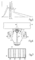
- FIG. 5 represents the energy spectrum of such an X-ray emitter which comprises an X-ray tube with a tungsten anode.
- the curve shown in dashed lines with S represents the spectrum (on a different scale than the spectrum P) that results when X-rays with the energy spectrum P in the examination area under a scattering angle of e.g. Is scattered 140 °.
- the radiation scattered at such an angle is essentially caused by Compton scattering processes which, according to equation (1), leads to an increasing energy loss with increasing energy of the X-ray quanta.
- the transmission jump caused by the absorption edge is due to the energy loss in the Compton scattering process at the lower energy E b .
- Spectral components above E b have a large attenuation and spectral components below E b have a low attenuation.
- the spectral components experience a lower attenuation below E b and higher attenuation above E a , although the attenuation effect on the primary side is slightly less than on the secondary side (with the same filter thickness). If you compensate for these differences in absorption or transmission by making the filter a little thicker on the primary side or - with the same thickness of the filter - increasing the measurement time accordingly if the filter is inserted on the secondary side, the influence of the spectral components increases below E b and above E a essentially when the signals obtained in the two measurements are subtracted from one another. This is not the case only in the area between E b and E a . The difference signal therefore corresponds to the signal that would result if the X-ray emitter only had X-ray quanta with an energy between E b and E a . The method described thus effects bandpass filtering.
- the difference formation results in a bandpass filter which makes X-ray quanta with energies in the range from 56 keV to 69.5 keV effective on the secondary side, which means an energy from 69.5 to 91.5 keV on the primary side. If you replace the tungsten filter with a cerium filter that has a K absorption edge at 40.45 KeV, this method results in an energy band between 35.5 and 40.45 keV on the secondary side or at a scattering angle of 140 °. from 40.45 to 47 keV on the primary side.
- the width of the energy band which is effective by this method, depends on the scattering angle and decreases with it. With a scattering angle of 90 °, for example, the energy band to be emphasized with a tungsten filter is sufficient from 61.2 keV to 69.5 keV on the secondary side or from 69.5 to 80.44 keV on the primary side.
- the device has a measuring head 15, which is provided with a gap 16 perpendicular to the plane of FIG. 6.
- the gap 16 fades out a fan-shaped beam bundle from the polychromatic beam bundle of an X-ray emitter, not shown, which strikes a rotatable roller 17 with a material that absorbs the X-ray radiation.
- two spirally extending slots are provided, which are offset from one another by 180 °, so that in each roller position a needle beam 18 is faded out of the fan-shaped beam 17, which is pivoted when the roller rotates in a plane perpendicular to the plane of the drawing.
- the needle beam 18 passes through an examination object 19 and generates (Compton) scattered radiation therein.
- the scattered radiation which is scattered at an angle of approximately 140 ° with the needle beam, passes through two slots 19 in the measuring head, which are perpendicular to the plane of the drawing and on both sides of the plane defined by the gap 16, and strikes two detector arrangements 20 each consisting of a plurality of detector elements in the measuring head.
- the detector elements which extend perpendicular to the plane of the drawing, detect the scattered radiation from different depths of the object because of the slot geometry.
- FIG. 6 the arrangement according to FIG. 6 is known from EP-PS 184 247.
- a filter arrangement 21 is provided in the beam path between the object 19 and the measuring head 15. With this filter arrangement, four different measurements are carried out for each position of the needle beam 18.
- the filter assembly comprises a holder 215 for four filter plates 210 .... 213th
- the two filter plates 210 and 211 are made of tungsten and have the same thickness.
- the two filter plates 212 and 213 are made of cerium and have the same thickness. There is a space between adjacent filter plates through which X-rays can pass unaffected.
- the filter In a first measurement, the filter is positioned in the beam path in such a way that the needle beam 18 can pass between the filter plates 210 and 211 without being weakened.
- the scattered radiation strikes the plates 210 and 211 on their way to the slots 19 and is influenced thereby.
- the filter is then moved laterally so that the filter plate 211 replaces the needle jet 18 in the second measurement.
- the scattered radiation then reaches the slots 19 unhindered.
- this second measurement takes somewhat longer than the first measurement.
- the measured values supplied by each individual element of the detector arrangements 20 for the same position of the needle beam 18 and the two positions of the filter arrangement 21 are subtracted from one another.
- the difference signal is equivalent to a measurement signal that would result if the spectrum of the X-ray emitter were restricted to a certain energy band (E b -E a - see FIG. 5).
- the cerium filter 212 is penetrated by the needle beam 18 in a third measurement.
- the scattered radiation reaches the detector arrangement 20 unhindered through the slots 19.
- the primary beam passes through the space between the two Cer filters 212 and 213 in a fourth measurement, which then filter the scattered radiation before it passes through the slots 19.
- the difference between the signals measured at the third and fourth positions of the filter arrangement is again formed, which results in a difference signal that corresponds to an energy band that is lower than the energy band that results from the difference of the first and the second measurement with the tungsten filters 210 and 211 results.
- Object 18 is thus irradiated with two different energies, which is essential for the so-called “dual energy” methods. These methods provide additional information about the examination subject 19.
- a dual-energy method can be carried out without the spectrum of the X-ray radiation generated by the X-ray emitter having to be changed, for example by switching over the high voltage that is present in the X-ray emitter X-ray tube is put on.
Landscapes
- Physics & Mathematics (AREA)
- Spectroscopy & Molecular Physics (AREA)
- Engineering & Computer Science (AREA)
- General Engineering & Computer Science (AREA)
- High Energy & Nuclear Physics (AREA)
- Analysing Materials By The Use Of Radiation (AREA)
- Apparatus For Radiation Diagnosis (AREA)
- Measurement Of Radiation (AREA)
Claims (7)
- Procédé de filtrage pour un système de rayons X Avec un générateur de rayons X émettant un quantum de rayons X et un dispositif détecteur produisant au moins un signal de mesure en vue de l'enregistrement des quantum de rayons X en interaction avec un objet dans une zone d'examen comportant les étapes de procédé suivantes :a) Une première mesure dans laquelle un filtre se trouve dans le trajet des rayons entre le générateur de rayons X et la zone d'examen est effectuée.b) Une autre mesure dans laquelle un filtre se trouve dans le trajet des rayons entre la zone d'examen et le dispositif détecteur, lequel filtre se compose du même matériau que le filtre utilisé pour la première mesure, est effectuée.c) Les signaux de mesure obtenus pour les deux mesures sont combinés l'un à l'autre par soustraction.
- Procédé de filtrage selon la revendication 1, caractérisé en ce qu'un générateur de rayons X essentiellement monochromatique est utilisé, que le matériau de filtrage présente une arête d'absorption pour une énergie quantique qui est légèrement inférieure à l'énergie des quantum de rayons X émis par le générateur de rayons X monochromatique, que les quantum de rayons X sont enregistrés par le dispositif détecteur dans un angle qui est inférieur à l'angle pour lequel la perte énergétique des quantum de rayons X par diffusion de Compton correspond précisément à la différence entre l'énergie des quantum de rayons X de l'énergie quantique à laquelle le filtre présente une arête d'absorption.
- Procédé de filtrage selon la revendication 1, caractérisé en ce qu'un générateur de rayons X essentiellement monochromatique est utilisé, que le matériau de filtrage présente une arête d'absorption pour une énergie quantique légèrement inférieure à l'énergie des quantum de rayons X émis par le générateur de rayons X monochromatique, que les quantum de rayons X sont enregistrés par le dispositif détecteur dans un angle inférieur à l'angle auquel la perte énergétique des quantum de rayons X par la diffusion de Compton correspond précisément à la différence entre l'énergie des quantum de rayons X et l'énergie quantique à laquelle le matériau de filtrage présente une arête d'absorption et que l'énergie est mesurée après dispersion de l'énergie.
- Procédé selon la revendication 1, caractérisé en ce qu'un générateur de rayons X polychromatique est utilisé et que le rayonnement diffusé sortant dans une gamme d'angles de diffusion déterminée est mesuré par le dispositif détecteur.
- Procédé de filtrage selon la revendication 2 ou 3, caractérisé en ce qu'un générateur de rayons X émettant un rayonnement fluorescent au tantale et un filtre d'erbium est utilisé.
- Dispositif d'exécution du procédé de filtrage selon la revendication 1 avec un système de rayons X doté d'un générateur de rayons X et d'un dispositif détecteur en vue de l'enregistrement des quantum de rayons X en interaction avec un objet d'examen, avec des moyens de filtrage en vue d'introduire un filtre pour la première mesure dans le trajet des rayons entre le générateur de rayons X et l'objet d'examen et dans le trajet des rayons entre l'objet d'examen et le détecteur pour l'autre mesure et avec des moyens en vue de la combinaison par soustraction des signaux de mesure produits par le dispositif détecteur.
- Dispositif selon la revendication 6 avec un générateur de rayons X polychromatique et un dispositif détecteur en vue de l'enregistrement du rayonnement diffusé dans un angle de plus d'environ 90°, caractérisé en ce qu'un dispositif de filtrage avec au moins un filtre plat est prévu et peut se déplacer perpendiculairement au trajet des rayons X s'étendant entre le générateur de rayons X et la zone d'examen dans au moins deux positions, le filtre étant pénétré par le rayonnement primaire dans l'une des positions et par le rayonnement diffusé dans l'autre position.
Applications Claiming Priority (2)
| Application Number | Priority Date | Filing Date | Title |
|---|---|---|---|
| DE4215343A DE4215343A1 (de) | 1992-05-09 | 1992-05-09 | Filterverfahren für ein Röntgensystem und Anordnung zur Durchführung eines solchen Filterverfahrens |
| DE4215343 | 1992-05-09 |
Publications (3)
| Publication Number | Publication Date |
|---|---|
| EP0571017A2 EP0571017A2 (fr) | 1993-11-24 |
| EP0571017A3 EP0571017A3 (fr) | 1995-05-31 |
| EP0571017B1 true EP0571017B1 (fr) | 1997-11-12 |
Family
ID=6458510
Family Applications (1)
| Application Number | Title | Priority Date | Filing Date |
|---|---|---|---|
| EP93201335A Expired - Lifetime EP0571017B1 (fr) | 1992-05-09 | 1993-05-07 | Procédé de filtrage pour un système rayons X et agencement pour réaliser ledit procédé de filtrage |
Country Status (4)
| Country | Link |
|---|---|
| US (1) | US5394454A (fr) |
| EP (1) | EP0571017B1 (fr) |
| JP (1) | JP3456722B2 (fr) |
| DE (2) | DE4215343A1 (fr) |
Families Citing this family (55)
| Publication number | Priority date | Publication date | Assignee | Title |
|---|---|---|---|---|
| US6438621B1 (en) | 1994-11-14 | 2002-08-20 | Microsoft Corporation | In-memory modification of computer programs |
| US5600700A (en) * | 1995-09-25 | 1997-02-04 | Vivid Technologies, Inc. | Detecting explosives or other contraband by employing transmitted and scattered X-rays |
| US5642393A (en) * | 1995-09-26 | 1997-06-24 | Vivid Technologies, Inc. | Detecting contraband by employing interactive multiprobe tomography |
| US5974111A (en) * | 1996-09-24 | 1999-10-26 | Vivid Technologies, Inc. | Identifying explosives or other contraband by employing transmitted or scattered X-rays |
| EP1120086A4 (fr) * | 1998-09-17 | 2003-05-21 | Quanta Vision Inc | Dispositif pour mammographie a angle reduit et variantes |
| US6249567B1 (en) * | 1998-12-01 | 2001-06-19 | American Science & Engineering, Inc. | X-ray back scatter imaging system for undercarriage inspection |
| DE19962281A1 (de) * | 1999-12-23 | 2001-06-28 | Philips Corp Intellectual Pty | Röntgenuntersuchungsgerät |
| US7010094B2 (en) * | 2000-02-10 | 2006-03-07 | American Science And Engineering, Inc. | X-ray inspection using spatially and spectrally tailored beams |
| US7538325B2 (en) * | 2000-02-10 | 2009-05-26 | American Science And Engineering, Inc. | Single-pulse-switched multiple energy X-ray source applications |
| US20080211431A1 (en) * | 2000-02-10 | 2008-09-04 | American Science And Engineering, Inc. | Pulse-to-Pulse-Switchable Multiple-Energy Linear Accelerators Based on Fast RF Power Switching |
| US6459761B1 (en) | 2000-02-10 | 2002-10-01 | American Science And Engineering, Inc. | Spectrally shaped x-ray inspection system |
| US20050117683A1 (en) * | 2000-02-10 | 2005-06-02 | Andrey Mishin | Multiple energy x-ray source for security applications |
| US9958569B2 (en) | 2002-07-23 | 2018-05-01 | Rapiscan Systems, Inc. | Mobile imaging system and method for detection of contraband |
| US8503605B2 (en) | 2002-07-23 | 2013-08-06 | Rapiscan Systems, Inc. | Four sided imaging system and method for detection of contraband |
| US8275091B2 (en) | 2002-07-23 | 2012-09-25 | Rapiscan Systems, Inc. | Compact mobile cargo scanning system |
| US7963695B2 (en) | 2002-07-23 | 2011-06-21 | Rapiscan Systems, Inc. | Rotatable boom cargo scanning system |
| US6928141B2 (en) | 2003-06-20 | 2005-08-09 | Rapiscan, Inc. | Relocatable X-ray imaging system and method for inspecting commercial vehicles and cargo containers |
| ATE530992T1 (de) * | 2003-08-21 | 2011-11-15 | Microsoft Corp | Elektronische tintenverarbeitung |
| US7809109B2 (en) * | 2004-04-09 | 2010-10-05 | American Science And Engineering, Inc. | Multiple image collection and synthesis for personnel screening |
| PL1733213T3 (pl) * | 2004-04-09 | 2010-07-30 | American Science & Eng Inc | Eliminowanie przesłuchu w bramce kontrolnej z rozpraszaniem wstecznym, zawierającej wiele źródeł, przez zapewnienie, że tylko jedno źródło emituje promieniowanie w tym samym czasie |
| GB0420222D0 (en) * | 2004-09-11 | 2004-10-13 | Koninkl Philips Electronics Nv | Coherent scatter imaging |
| DE102004060609A1 (de) * | 2004-12-16 | 2006-06-29 | Yxlon International Security Gmbh | Verfahren zum Messen des Impulsübertragungsspektrums von elastisch gestreuten Röntgenquanten |
| US7471764B2 (en) | 2005-04-15 | 2008-12-30 | Rapiscan Security Products, Inc. | X-ray imaging system having improved weather resistance |
| JP2007071697A (ja) * | 2005-09-07 | 2007-03-22 | Jeol Ltd | X線分析装置 |
| MX2008013595A (es) * | 2006-04-21 | 2009-03-06 | American Science & Eng Inc | Formacion de imagenes de rayos x de equipaje y de personal utilizando disposiciones de fuentes discretas y multiples haces colimados. |
| US7526064B2 (en) | 2006-05-05 | 2009-04-28 | Rapiscan Security Products, Inc. | Multiple pass cargo inspection system |
| US7646850B2 (en) * | 2007-01-18 | 2010-01-12 | The Research Foundation Of State University Of New York | Wide-field, coherent scatter imaging for radiography using a divergent beam |
| US8995619B2 (en) | 2010-03-14 | 2015-03-31 | Rapiscan Systems, Inc. | Personnel screening system |
| US8638904B2 (en) | 2010-03-14 | 2014-01-28 | Rapiscan Systems, Inc. | Personnel screening system |
| US8576982B2 (en) | 2008-02-01 | 2013-11-05 | Rapiscan Systems, Inc. | Personnel screening system |
| GB0809110D0 (en) | 2008-05-20 | 2008-06-25 | Rapiscan Security Products Inc | Gantry scanner systems |
| WO2010032163A1 (fr) * | 2008-09-16 | 2010-03-25 | Koninklijke Philips Electronics N.V. | Appareil d'imagerie comprenant une unité de correction du rayonnement diffusé |
| US8824632B2 (en) | 2009-07-29 | 2014-09-02 | American Science And Engineering, Inc. | Backscatter X-ray inspection van with top-down imaging |
| EP2459991B1 (fr) * | 2009-07-29 | 2019-09-11 | American Science & Engineering, Inc. | Remorque d'inspection de haut en bas par rayons x |
| CN102893181A (zh) | 2010-03-14 | 2013-01-23 | 拉皮斯坎系统股份有限公司 | 多屏检测系统 |
| PL3270185T3 (pl) | 2011-02-08 | 2023-06-12 | Rapiscan Systems, Inc. | Niejawny nadzór z wykorzystaniem wielomodalnościowego wykrywania |
| US9218933B2 (en) | 2011-06-09 | 2015-12-22 | Rapidscan Systems, Inc. | Low-dose radiographic imaging system |
| AU2013215064B2 (en) | 2012-02-03 | 2015-10-22 | Rapiscan Systems, Inc. | Combined scatter and transmission multi-view imaging system |
| US10670740B2 (en) | 2012-02-14 | 2020-06-02 | American Science And Engineering, Inc. | Spectral discrimination using wavelength-shifting fiber-coupled scintillation detectors |
| DE102013200839A1 (de) * | 2013-01-21 | 2014-04-17 | Siemens Aktiengesellschaft | Röntgenstreuung mit einem energieauflösenden Detektor |
| WO2014121097A1 (fr) | 2013-01-31 | 2014-08-07 | Rapiscan Systems, Inc. | Système d'inspection de sécurité portable |
| BR112016020638A2 (pt) | 2014-03-07 | 2018-06-19 | Rapiscan Systems, Inc. | detetores de ultra banda larga |
| US11280898B2 (en) | 2014-03-07 | 2022-03-22 | Rapiscan Systems, Inc. | Radar-based baggage and parcel inspection systems |
| GB2548299B (en) | 2014-11-25 | 2022-04-27 | Rapiscan Systems Inc | Intelligent security management system |
| PL3271709T3 (pl) | 2015-03-20 | 2023-02-20 | Rapiscan Systems, Inc. | Ręczny przenośny system kontroli rozpraszania wstecznego |
| US20170245819A1 (en) * | 2016-02-26 | 2017-08-31 | Peter J. Rothschild | Systems and methods for in-vivo detection of lead in bone |
| JP6759056B2 (ja) * | 2016-10-28 | 2020-09-23 | キヤノン株式会社 | 放射線検出装置及び放射線撮像システム |
| EP3226038B1 (fr) * | 2016-03-28 | 2020-05-06 | Canon Kabushiki Kaisha | Appareil de détection de rayonnement et système d'imagerie par rayonnement |
| WO2018064434A1 (fr) | 2016-09-30 | 2018-04-05 | American Science And Engineering, Inc. | Source de rayons x pour imagerie à faisceau de balayage 2d |
| WO2019245636A1 (fr) | 2018-06-20 | 2019-12-26 | American Science And Engineering, Inc. | Détecteurs de scintillation couplés à une feuille à décalage de longueur d'onde |
| WO2021246998A1 (fr) * | 2020-06-01 | 2021-12-09 | American Science And Engineering, Inc. | Systèmes et méthodes pour commander le contraste d'image dans un système radiographique |
| US11193898B1 (en) | 2020-06-01 | 2021-12-07 | American Science And Engineering, Inc. | Systems and methods for controlling image contrast in an X-ray system |
| US11175245B1 (en) | 2020-06-15 | 2021-11-16 | American Science And Engineering, Inc. | Scatter X-ray imaging with adaptive scanning beam intensity |
| CN114166874A (zh) * | 2020-09-11 | 2022-03-11 | 同方威视技术股份有限公司 | 背散射检查系统和方法 |
| US11340361B1 (en) | 2020-11-23 | 2022-05-24 | American Science And Engineering, Inc. | Wireless transmission detector panel for an X-ray scanner |
Family Cites Families (10)
| Publication number | Priority date | Publication date | Assignee | Title |
|---|---|---|---|---|
| US4445226A (en) * | 1981-05-05 | 1984-04-24 | The Board Of Trustees Of The Leland Stanford Junior University | Multiple-energy X-ray subtraction imaging system |
| US4611341A (en) * | 1981-05-05 | 1986-09-09 | The Board Of Trustees Of The Leland Stanford Junior University | Multiple-energy x-ray substraction imaging system |
| US4541106A (en) * | 1984-02-22 | 1985-09-10 | General Electric Company | Dual energy rapid switching imaging system |
| DE3443095A1 (de) * | 1984-11-27 | 1986-05-28 | Philips Patentverwaltung Gmbh, 2000 Hamburg | Anordnung zur untersuchung eines koerpers mit gamma- oder roentgenstrahlung |
| DE3716618A1 (de) * | 1987-05-18 | 1988-12-08 | Philips Patentverwaltung | Strahlenquelle zur erzeugung einer im wesentlichen monochromatischen roentgenstrahlung |
| US4945552A (en) * | 1987-12-04 | 1990-07-31 | Hitachi, Ltd. | Imaging system for obtaining X-ray energy subtraction images |
| DE69033232T2 (de) * | 1989-12-14 | 1999-12-30 | Aloka Co Ltd | Vorrichtung zur Messung des Kalziumgehaltes von Knochen |
| DE4000507A1 (de) * | 1990-01-10 | 1991-07-11 | Philips Patentverwaltung | Anordnung zur untersuchung eines pruefobjekts mit gamma- oder roentgenstrahlung |
| DE4034602A1 (de) * | 1990-06-20 | 1992-05-07 | Philips Patentverwaltung | Anordnung zur messung des impulsuebertragsspektrums von roentgenquanten |
| US5157074A (en) * | 1991-07-23 | 1992-10-20 | Miles Inc. | Aqueous compositions containing an at least partially blocked polyisocyanates and a trimerization catalyst and coatings and binders prepared therefrom |
-
1992
- 1992-05-09 DE DE4215343A patent/DE4215343A1/de not_active Withdrawn
-
1993
- 1993-05-07 JP JP10707193A patent/JP3456722B2/ja not_active Expired - Fee Related
- 1993-05-07 EP EP93201335A patent/EP0571017B1/fr not_active Expired - Lifetime
- 1993-05-07 DE DE59307657T patent/DE59307657D1/de not_active Expired - Fee Related
- 1993-05-07 US US08/060,174 patent/US5394454A/en not_active Expired - Fee Related
Also Published As
| Publication number | Publication date |
|---|---|
| DE59307657D1 (de) | 1997-12-18 |
| US5394454A (en) | 1995-02-28 |
| JP3456722B2 (ja) | 2003-10-14 |
| DE4215343A1 (de) | 1993-11-11 |
| EP0571017A3 (fr) | 1995-05-31 |
| JPH0638949A (ja) | 1994-02-15 |
| EP0571017A2 (fr) | 1993-11-24 |
Similar Documents
| Publication | Publication Date | Title |
|---|---|---|
| EP0571017B1 (fr) | Procédé de filtrage pour un système rayons X et agencement pour réaliser ledit procédé de filtrage | |
| EP0153786B1 (fr) | Appareil à rayons X | |
| EP0209952B1 (fr) | Procédé pour la mesure de la répartition spatiale de rayonnement X diffusé élastiquement ainsi que le dispositif pour la mise en oeuvre du procédé | |
| EP0496454B1 (fr) | Appareil de radiographie | |
| EP0311177B1 (fr) | Système pour examiner un corps avec une source de rayonnement | |
| EP0360347B1 (fr) | Dispositif pour la mesure du spectre de transfert d'impulsions | |
| DE60132556T2 (de) | Röntgeninspektionssystem mit gefiltertem strahl | |
| DE2733586C2 (fr) | ||
| EP0242895B1 (fr) | Procédé pour la détermination de la structure spatiale dans une couche de la zone examinée | |
| DE2544354A1 (de) | Verfahren zur bestimmung der dichte von koerpern mittels durchdingender strahlen und geraet zu seiner durchfuehrung | |
| EP1127546A2 (fr) | Tomographe assisté par ordinateur pour détecter le spectre de transmission d'impulsions dans une zone d'inspection | |
| EP0259921A2 (fr) | Procédé pour formation en 2 dimensions des images de profil Compton | |
| DE2358237A1 (de) | Vorrichtung zur bestimmung des gehalts an mindestens einem chemischen element in einer substanz mittels eines elektromagnetischen strahlungsmessverfahrens | |
| DE2432305A1 (de) | Verfahren und vorrichtung zur untersuchung eines koerpers mittels durchdringender strahlung | |
| DE2244160B2 (de) | Vorrichtung für die Röntgenanalyse | |
| EP0217464B1 (fr) | Procédé pour la détermination de l'atténuation photonique dans un domaine d'un corps et dispositif pour la mise en oeuvre du procédé | |
| DE2831038C2 (de) | Strahlendiagnostikgerät für die Erzeugung von Schichtbildern | |
| DE3035929C2 (de) | Vorrichtung zur Ermittlung der Volumenanteile eines Mehrkomponentengemisches durch Transmission mehrerer Gammalinien | |
| DE3300406A1 (de) | Referenzdetektorvorrichtung fuer multidetektor-tomodensitometer und mit dieser vorrichtung ausgeruestetes tomodensitometer | |
| DE2412161A1 (de) | Anordnung zur bestimmung des kalziumgehaltes von knochen | |
| EP2217946B1 (fr) | Dispositif pour la détermination en ligne du contenu d'une substance et procédé utilisant un tel dispositif | |
| DE2426794A1 (de) | Einrichtung zur strahlungsfeststellung und verfahren zur feststellung des vorhandenseins eines interessierenden elementes in einer probe | |
| DE19603000A1 (de) | Verfahren zum Kalibrieren einer Anordnung zur Ermittlung des Impulsübertragsspektrums und Kalibriereinheit zur Durchführung des Verfahrens | |
| DE3300566C2 (fr) | ||
| DE2001513A1 (de) | Vorrichtung zur Messung des Gehalts einer Probe an einem Element durch Gamma-Absorptiometrie |
Legal Events
| Date | Code | Title | Description |
|---|---|---|---|
| PUAI | Public reference made under article 153(3) epc to a published international application that has entered the european phase |
Free format text: ORIGINAL CODE: 0009012 |
|
| AK | Designated contracting states |
Kind code of ref document: A2 Designated state(s): DE FR GB |
|
| RAP1 | Party data changed (applicant data changed or rights of an application transferred) |
Owner name: N.V. PHILIPS' GLOEILAMPENFABRIEKEN Owner name: PHILIPS PATENTVERWALTUNG GMBH |
|
| PUAL | Search report despatched |
Free format text: ORIGINAL CODE: 0009013 |
|
| AK | Designated contracting states |
Kind code of ref document: A3 Designated state(s): DE FR GB |
|
| 17P | Request for examination filed |
Effective date: 19951130 |
|
| GRAG | Despatch of communication of intention to grant |
Free format text: ORIGINAL CODE: EPIDOS AGRA |
|
| 17Q | First examination report despatched |
Effective date: 19970206 |
|
| GRAH | Despatch of communication of intention to grant a patent |
Free format text: ORIGINAL CODE: EPIDOS IGRA |
|
| GRAH | Despatch of communication of intention to grant a patent |
Free format text: ORIGINAL CODE: EPIDOS IGRA |
|
| GRAA | (expected) grant |
Free format text: ORIGINAL CODE: 0009210 |
|
| AK | Designated contracting states |
Kind code of ref document: B1 Designated state(s): DE FR GB |
|
| REF | Corresponds to: |
Ref document number: 59307657 Country of ref document: DE Date of ref document: 19971218 |
|
| GBT | Gb: translation of ep patent filed (gb section 77(6)(a)/1977) |
Effective date: 19980123 |
|
| ET | Fr: translation filed | ||
| RAP4 | Party data changed (patent owner data changed or rights of a patent transferred) |
Owner name: KONINKLIJKE PHILIPS ELECTRONICS N.V. Owner name: PHILIPS PATENTVERWALTUNG GMBH |
|
| PLBE | No opposition filed within time limit |
Free format text: ORIGINAL CODE: 0009261 |
|
| REG | Reference to a national code |
Ref country code: FR Ref legal event code: CD |
|
| STAA | Information on the status of an ep patent application or granted ep patent |
Free format text: STATUS: NO OPPOSITION FILED WITHIN TIME LIMIT |
|
| 26N | No opposition filed | ||
| REG | Reference to a national code |
Ref country code: GB Ref legal event code: IF02 |
|
| REG | Reference to a national code |
Ref country code: FR Ref legal event code: D6 |
|
| REG | Reference to a national code |
Ref country code: GB Ref legal event code: 746 Effective date: 20021107 |
|
| PGFP | Annual fee paid to national office [announced via postgrant information from national office to epo] |
Ref country code: FR Payment date: 20040527 Year of fee payment: 12 |
|
| PGFP | Annual fee paid to national office [announced via postgrant information from national office to epo] |
Ref country code: GB Payment date: 20040528 Year of fee payment: 12 |
|
| PGFP | Annual fee paid to national office [announced via postgrant information from national office to epo] |
Ref country code: DE Payment date: 20040714 Year of fee payment: 12 |
|
| PG25 | Lapsed in a contracting state [announced via postgrant information from national office to epo] |
Ref country code: GB Free format text: LAPSE BECAUSE OF NON-PAYMENT OF DUE FEES Effective date: 20050507 |
|
| PG25 | Lapsed in a contracting state [announced via postgrant information from national office to epo] |
Ref country code: DE Free format text: LAPSE BECAUSE OF NON-PAYMENT OF DUE FEES Effective date: 20051201 |
|
| GBPC | Gb: european patent ceased through non-payment of renewal fee |
Effective date: 20050507 |
|
| PG25 | Lapsed in a contracting state [announced via postgrant information from national office to epo] |
Ref country code: FR Free format text: LAPSE BECAUSE OF NON-PAYMENT OF DUE FEES Effective date: 20060131 |
|
| REG | Reference to a national code |
Ref country code: FR Ref legal event code: ST Effective date: 20060131 |