EP0571017B1 - Filtering procedure for an X-ray system and arrangement to carry out such a filtering procedure - Google Patents
Filtering procedure for an X-ray system and arrangement to carry out such a filtering procedure Download PDFInfo
- Publication number
- EP0571017B1 EP0571017B1 EP93201335A EP93201335A EP0571017B1 EP 0571017 B1 EP0571017 B1 EP 0571017B1 EP 93201335 A EP93201335 A EP 93201335A EP 93201335 A EP93201335 A EP 93201335A EP 0571017 B1 EP0571017 B1 EP 0571017B1
- Authority
- EP
- European Patent Office
- Prior art keywords
- filter
- ray
- energy
- quanta
- measurement
- Prior art date
- Legal status (The legal status is an assumption and is not a legal conclusion. Google has not performed a legal analysis and makes no representation as to the accuracy of the status listed.)
- Expired - Lifetime
Links
Images
Classifications
-
- G—PHYSICS
- G21—NUCLEAR PHYSICS; NUCLEAR ENGINEERING
- G21K—TECHNIQUES FOR HANDLING PARTICLES OR IONISING RADIATION NOT OTHERWISE PROVIDED FOR; IRRADIATION DEVICES; GAMMA RAY OR X-RAY MICROSCOPES
- G21K1/00—Arrangements for handling particles or ionising radiation, e.g. focusing or moderating
- G21K1/10—Scattering devices; Absorbing devices; Ionising radiation filters
Description
Die Erfindung betrifft ein Filterverfahren für ein Röntgensystem sowie eine Anordnung zur Durchführung dieses Filterverfahrens. Aus der Zeitschrift J. Phys.E., Vol. 18, 1985, Seiten 354-357 ist ein Filterverfahren für ein Röntgensystem bekannt, das einen Untersuchungsbereich durchstrahlt, wobei die Röntgenstrahlung aus dem Untersuchungsbereich von einer Detektoranordnung gemessen wird. Bei dem bekannten Verfahren wird eine erste Messung mit einem ersten Filter im Strahlengang zwischen Röntgenstrahler und Untersuchungsbereich durchgeführt und eine zweite Messung mit einem zweiten Filter. Die beiden Filter besitzen unterschiedliche Absorptionskanten und sind so bemessen, daß sie für alle Röntgenquanten außerhalb des Energiebereiches zwischen den Absorptionskanten der beiden Filter die gleiche Absorption bzw. Transmission aufweisen. Wird das Ergebnis der beiden Messungen voneinander subtrahiert, dann resultiert ein Differenzwert, der nur von den Spektralkomponenten des polychromatischen Röntgenstrahlers abhängt, die innerhalb des Energiebereiches zwischen den beiden Absorptionskanten liegen.The invention relates to a filter method for an X-ray system and an arrangement for carrying out this filter method. From the journal J. Phys.E., Vol. 18, 1985, pages 354-357, a filter method for an X-ray system is known which irradiates an examination area, the X-ray radiation from the examination area being measured by a detector arrangement. In the known method, a first measurement is carried out with a first filter in the beam path between the X-ray emitter and the examination area and a second measurement is carried out with a second filter. The two filters have different absorption edges and are dimensioned such that they have the same absorption or transmission for all X-ray quanta outside the energy range between the absorption edges of the two filters. If the result of the two measurements is subtracted from one another, a difference value results which only depends on the spectral components of the polychromatic X-ray emitter which lie within the energy range between the two absorption edges.
Aufgabe der vorliegenden Erfindung ist es, ein anderes Filterverfahren anzugeben. Diese Aufgabe wird erfindungsgemäß gelöst durch ein Filterverfahren für ein Röntgen-System mit einem Röntgenquanten emittierenden Röntgenstrahler und einer wenigstens ein Meßsignal liefernden Detektoranordnung zur Erfassung der mit einem Objekt in einem Untersuchungsbereich in Wechselwirkung getretenen Röntgenquanten mit folgenden Verfahrensschritten:
- a) Es wird eine Messung durchgeführt, bei der sich im Strahlengang zwischen dem Röntgenstrahler und dem Untersuchungsbereich ein Filter befindet.
- b) Es wird eine Messung durchgeführt, bei der sich im Strahlengang zwischen dem Untersuchungsbereich und der Detektoranordnung ein Filter befindet, das aus dem gleichen Material besteht wie das bei der anderen Messung benutzte Filter.
- c) Die bei den beiden Messungen erhaltenen Meßsignale werden subtraktiv miteinader kombiniert.
- a) A measurement is carried out in which there is a filter in the beam path between the X-ray emitter and the examination area.
- b) A measurement is carried out in which there is a filter in the beam path between the examination area and the detector arrangement, which is made of the same material as the filter used in the other measurement.
- c) The measurement signals obtained in the two measurements are combined with each other subtractively.
Während also bei dem bekannten Verfahren bei zwei Messungen Filter aus unterschiedlichem Material jeweils im Strahlengang zwischen Röntgenstrahler und Untersuchungsbereich plaziert werden, wird bei der Erfindung bei der einen Messung ein Filter in den Strahlengang zwischen Röntgenstrahler und Untersuchungsbereich und bei der anderen Messung ein Filter in den Strahlengang zwischen dem Untersuchungsbereich und der Detektoranordnung plaziert, wobei das Filtermaterial in beiden Fällen dasselbe ist. Deshalb kann bei beiden Messungen das gleiche Filter verwendet werden. Es ist jedoch auch möglich, zwei Filter aus demselben Material zu verwenden.Thus, while in the known method with two measurements, filters made of different materials are placed in the beam path between the X-ray source and the examination area, in the case of the invention, a filter is placed in the beam path between the X-ray source and the examination area, and in the other measurement a filter is placed in the beam path placed between the examination area and the detector arrangement, the filter material being the same in both cases. The same filter can therefore be used for both measurements. However, it is also possible to use two filters made of the same material.
Die Erfindung nutzt die Tatsache aus, daß Röntgenquanten mit einem Objekt im Untersuchungsbereich in unterschiedlicher Weise in Wechselwirkung treten können:
- 1) Bei der elastischen Streustrahlung (Rayleigh-Streuung) ändert sich zwar die Richtung der Röntgenstrahlung, nicht aber ihre Energie.
- 2) Bei der inelastischen (Compton-Streuung) verliert die Röntgenstrahlung bei einer Richtungsänderung Energie. Der Energieverlust hängt von der Größe der Richtungsänderung und von der Energie der Röntgenquanten ab.
- 3) Bei der photoelektronischen Bremsstrahlung wird durch ein mit einem Atom in Wechselwirkung tretendes Röntgenquant ein Elektron vornehmlich aus der K-Schale befreit, wodurch ein Photoelektron (Röntgenquant) entsteht, dessen Energie um den Betrag kleiner ist als die Energie des primären Röntgenquants, der erforderlich ist, um das Elektron aus der K-Schale zu lösen. Dieser Energiebetrag steigt kubisch mit der Ordnungszahl des Atoms im periodischen System an.
- 1) With elastic scattered radiation (Rayleigh scattering) the direction of the X-ray radiation changes, but not its energy.
- 2) With inelastic (Compton scattering), the X-ray radiation loses energy when the direction changes. The energy loss depends on the size of the change of direction and on the energy of the X-ray quanta.
- 3) In the case of photoelectronic brake radiation, an X-ray quantum interacting with an atom primarily frees an electron from the K shell, which creates a photoelectron (X-ray quantum) whose energy is smaller than the energy of the primary X-ray quantum that is required is to release the electron from the K shell. This amount of energy increases cubically with the atomic number in the periodic system.
Das erfindungsgemäße Verfahren gestattet es, die Komponenten, die durch unterschiedliche Wechselwirkung mit dem Untersuchungsbereich entstanden sind, voneinander zu trennen.The method according to the invention makes it possible to separate the components which have arisen from different interactions with the examination area.
Eine erste Weiterbildung der Erfindung sieht vor, daß ein im wesentlichen monochromatischer Röntgenstrahler verwendet wird, daß das Filtermaterial eine Absorptionskante bei einer Quantenenergie hat, die geringfügig niedriger ist als die Energie der von dem monochromatischen Röntgenstrahler emittierten Röntgenquanten und daß die Röntgenquanten von der Detektoranordnung unter einem Winkel erfaßt werden, der größer ist als der Winkel, bei dem der Energieverlust der Röntgenquanten durch Compton-Streuung gerade der Differenz zwischen der Energie der Röntgenquanten und der Quantenenergie entspricht, bei der das Filter seine Absorptionskante hat. Dieses Verfahren gestattet die Bestimmung des Streuquerschnitts für elastische (kohärente) Streustrahlung oder auch für inelastische (inkohärente) Streustrahlung.A first further development of the invention provides that an essentially monochromatic x-ray emitter is used, that the filter material has an absorption edge at a quantum energy which is slightly lower than the energy of the x-ray quanta emitted by the monochromatic x-ray emitter and that the x-ray quanta from the detector arrangement under one An angle is detected that is greater than the angle at which the energy loss of the X-ray quanta by Compton scattering corresponds exactly to the difference between the energy of the X-ray quanta and the quantum energy at which the filter has its absorption edge. This method allows the scatter cross section to be determined for elastic (coherent) scatter radiation or also for inelastic (incoherent) scatter radiation.
Nach einer anderen Ausgestaltung der Erfindung ist vorgesehen, daß ein im wesentlichen monochromatischer Röntgenstrahler verwendet wird, daß das Filtermaterial eine Absorptionskante bei einer Quantenenergie hat, die geringfügig niedriger ist als die Energie der von dem monochromatischen Röntgenstrahler emittierten Röntgenquanten, daß die Röntgenquanten von der Detektoranordnung unter einem Winkel erfaßt werden, der kleiner ist als der Winkel, bei dem der Energieverlust der Röntgenquanten durch Compton-Streuung gerade die Differenz zwischen der Energie der Röntgenquanten und der Energie der Röntgenquanten entspricht, bei der das Filtermaterial eine Absorptionskante aufweist, und daß die Quantenenergie energieauflösend gemessen wird. Bei dieser Ausgestaltung können die auf Compton- und Rayleigh-Streuung zurückgehenden Komponenten unterdrückt werden, so daß nur Komponenten verbleiben, die durch photoelektronische Bremsstrahlung erzeugt werden. Man kann damit in einem (ausgedehnten) Untersuchungsbereich den Gehalt von Stoffen mit niedriger Ordnungszahl, z.B. Kohlenstoff, Sauerstoff bzw. Stickstoff) bestimmen.According to another embodiment of the invention it is provided that an essentially monochromatic x-ray emitter is used, that the filter material has an absorption edge at a quantum energy which is slightly lower than the energy of the x-ray quanta emitted by the monochromatic x-ray emitter, that the x-ray quanta are below the detector arrangement an angle is detected that is smaller than the angle at which the energy loss of the X-ray quanta by Compton scattering corresponds exactly to the difference between the energy of the X-ray quanta and the energy of the X-ray quanta at which the filter material has an absorption edge and that the quantum energy is energy-resolving is measured. With this configuration, the components due to Compton and Rayleigh scattering can be suppressed, so that only components remain which are generated by photoelectronic braking radiation. It can be used to determine the content of substances with a low atomic number, e.g. Determine carbon, oxygen or nitrogen).
Eine weitere Ausgestaltung der Erfindung sieht vor, daß ein polychromatischer Röntgenstrahler verwendet wird, und daß die unter einem bestimmten Streuwinkelbereich austretende Streustrahlung von der Detektoranordnung gemessen wird. Die nach subtraktiver Kombination der Meßsignale erhaltenen Meßwerte werden nur von Röntgenquanten innerhalb eines bestimmten Energiebandes bestimmt; die Wirkung der anderen Röntgenquanten wird durch die subtraktive Kombination eliminiert.Another embodiment of the invention provides that a polychromatic x-ray emitter is used and that the scattered radiation emerging under a certain scattering angle range is measured by the detector arrangement. The measured values obtained after subtractive combination of the measurement signals are only determined by X-ray quanta within a certain energy band; the effect of the other X-ray quanta is eliminated by the subtractive combination.
Die Erfindung wird nachstehend anhand der Zeichnungen näher erläutert. Es zeigen:
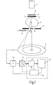
- Fig. 1 eine Anordnung zur Durchführung des erfindungsgemäßen Filterverfahrens.
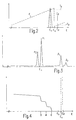
- Fig. 2 ein Spektrum, das sich bei einer Ausführungsform jenseits des Untersuchunbsbereiches ergibt.
- Fig. 3 die Emissionslinien eines für das Verfahren geeigneten monochromatischen Röntgenstrahlers.
- Fig. 4 das Energiespektrum, das sich bei einer anderen Ausführungsform ergibt.
- Fig. 5 ein Bremsstrahlungsspektrum vor und hinter dem Untersuchungsbereich.
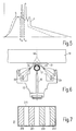
- Fig. 6 eine zweite Ausführungsform des erfindungsgemäßen Verfahrens und
- Fig. 7 ein bei der Anordnung nach Fig. 6 verwendbares Filter.
- Fig. 1 shows an arrangement for performing the filter method according to the invention.
- 2 shows a spectrum which results in one embodiment beyond the examination area.
- 3 shows the emission lines of a monochromatic X-ray emitter suitable for the method.
- Fig. 4 shows the energy spectrum that results in another embodiment.
- 5 shows a brake radiation spectrum in front of and behind the examination area.
- Fig. 6 shows a second embodiment of the method according to the invention and
- FIG. 7 shows a filter that can be used in the arrangement according to FIG. 6.
In Fig. 1 ist mit 1 ein Röntgenstrahler bezeichnet, der monochromatische Röntgenstrahlung emittiert; die von dem Strahler 1 emittierten Röntgenquanten haben also alle im wesentlichen die gleiche Energie. Eine mit einer zentralen Bohrung versehene Blende 2 läßt von der von dem Röntgenstrahler 1 emittierten Röntgenstrahlenbündel nur einen Nadelstrahl (pencil-beam) 3 durch. Der Nadelstrahl 3 durchsetzt die zentrale Öffnung in einer weiteren Blendenplatte 4. Die beiden Blendenplatten 2 und 4 begrenzen in Richtung senkrecht zu dem Nadelstrahl 3 einen Untersuchungsbereich, in dem sich ein Untersuchungsobjekt 7 befindet. Die Röntgenquanten in dem Nadelstrahl 3 treten mit dem Untersuchungsobjekt 7 in Wechselwirkung, und erzeugen u.a. elastische und inelastische Streustrahlung. Die Streustrahlung, die im Untersuchungsobjekt 7 zwischen einem minimalen Winkel β1 und einem maximalen Winkel β2 erzeugt wird, kann durch eine zum Nadelstrahl 3 konzentrische, ringförmige Öffnung 8 in der Blende 4 hindurch einen ringförmigen Detektor 9 erreichen. Das Detektorsignal wird von einem integrierend wirkenden Verstärker 10 verstärkt und von einem Analog-Digital-Wandler in ein digitales Datenwort umgesetzt. Dieses Datenwort ist der Zahl der während eines Integrationsintervalls bzw. einer Meßzeit vom ringförmigen Detektor 9 registrierten Röntgenquanten proportional und von der Energie der Röntgenquanten unabhängig.In Fig. 1, 1 denotes an X-ray emitter which emits monochromatic X-ray radiation; the X-ray quanta emitted by the
Das Datenwort kann in einem Speicher 12 gespeichert und in einer arithmetisch logischen Einheit (ALU 13) weiterverarbeitet werden. Die Einheiten 10-13 werden von einer Steuereinheit 14 gesteuert. Die Einheiten 12-14 können Teil eines Microprozessors sein.The data word can be stored in a
Im folgenden wird die Durchführung eines Meßverfahrens mit Hilfe der in Fig. 1 skizzierten Anordnung erläutert. Es wird zunächst eine erste Messung durchgeführt. Bei dieser ersten Messung befindet sich im Strahlengang zwischen dem monochromatischen Röntgenstrahler 1 und dem Untersuchungsbereich 7 ein Filter 5, das eine Absorptionskante bei einer Quantenenergie Ek hat, die geringfügig niedriger liegt als die Energie der von dem Röntgenstrahler 1 emittierten Röntgenquanten.In the following, the implementation of a measuring method is explained using the arrangement outlined in FIG. 1. A first measurement is carried out first. In this first measurement, there is a
Fig. 2 zeigt das Energiespektrum (d.h. die Intensität der Röntgenstrahlung als Funktion der Energie der Röntgenquanten). Man erkennt in dem Spektrum eine Linie Ep und eine Komponente Es mit geringerer Energie. Die Linie Ep entsteht durch elastische Streuung, bei der die Röntgenquanten bekanntlich keine Energie verlieren. Die Energie Ep ist daher auch die Energie der vom Röntgenstrahler 1 emittierten Röntgenquanten. Die Komponente Es entsteht durch Compton-Streuung. Bei diesem inelastischen Streuprozeß verlieren die Röntgenquanten Energie gemäß der Beziehung![]()
![]()
Dabei ist Ep die Energie des Röntgenquants vor dem Streuproßeß, Es die Energie des Röntgenquants, nach dem Streuprozeß c eine Konstante und β der Winkel, den die Bahn des gestreuten Röntgenquants mit der Richtung des Nadelstrahls 3 einschließt.E p is the energy of the X-ray quantum before the scattering process, E s is the energy of the X-ray quantum, after the scattering process c is a constant and β is the angle that the path of the scattered X-ray quantum includes with the direction of the
Bei Gleichung (1) wird vorausgesetzt, daß die Elektronen stationär sind. In der Realität bewegen sich die Elektronen aber. Dies führt zu einer Verbreiterung der Compton-Linie (Compton-shift). In diesem Fall beschreibt Gleichung (1) die Energie des Compton-peaks. Für Streuung unter einem kleinen Streuwinkel ist die Breite des Compton-peaks klein.Equation (1) assumes that the electrons are stationary. In reality, however, the electrons move. This leads to a widening of the Compton line (Compton shift). In this case, equation (1) describes the Energy of the Compton peak. The width of the Compton peak is small for scattering under a small scattering angle.
Die Verbreiterung der Komponente Es im Vergleich zur Komponente Ep ergibt sich auch dadurch, daß Röntgenquanten den Detektorring 9 unter unterschiedlichen Streuwinkeln erreichen können. Wenn dafür gesorgt wird, daß Streustrahlung nur unter einem definierten Streuwinkel die Detektoranordnung erreichen kann, ergibt sich für die Komponente Es näherungsweise eine Linie. Dies kann beispielsweise dadurch erreicht werden, daß anstelle eines nadelförmigen Primärstrahls ein Primärstrahlenbündel mit der Form eines Kegelmantels verwendet wird und die Blende 4 durch zur Symmetrieachse des Kegelmantels konzentrische Kollimatorkörper gebildet wid, wie in der DE-OS 40 34 602 beschrieben.The broadening of the component E s compared to the component E p also results from the fact that X-ray quanta can reach the
Das in Fig. 1 dargestellte Filter 5 besteht aus einem Material mit einer Absorptionskante bei einer Quantenenergie Ek, die geringfügig kleiner ist als die Energie der vom Röntgenstrahler emittierten Röntgenquanten aber größer als die Energie Es der durch den Streuprozeß beeinflußten Röntgenquanten. In Fig. 2 ist der Verlauf der Transmission dieses Filters als Funktion der Energie der Röntgenquanten durch eine gestrichelte Kurve F schematisch angedeutet. Die Transmission nimmt bis zur Absorptionskante monoton zu, um dann auf einen niedrigen Wert zu springen und danach wieder anzusteigen. Die Transmission des Filters 5 für die Energie der Primärstrahlung ist mit Tp, und die (größere) Transmission des Filters für die Energie Es ist mit Ts bezeichnet. Durch den Einsatz des Filters 5 im Bereich zwischen Röntgenstrahler und Untersuchungsbereich werden die Spektralkomponenten Es und Ep im gleichen Maße reduziert - und zwar entsprechend dem Transmissionsfaktor Tp.The
Am Ende des Meßzeitraumes liefert der Analog-Digital-Wandler 11 ein Signal, das dem zeitlichen Integral über die Intensität proportional ist.At the end of the measurement period, the analog-
Danach wird eine weitere Messung durchgeführt, bei der - wie durch Pfeile angedeutet - das Filter 5 aus dem Strahlengang und ein Filter 6 in den Strahlengang zwischen dem Untersuchungsbereich 7 und der Detektoranordnung 9 bewegt wird. Das Filter 6 muß aus dem gleichen Material bestehen wie das Filter 5 und kann dieselbe Dicke haben. Im letzteren Fall könnte man mit einem Filter auskommen, das bei der einen Messung oberhalb des Untersuchungsbereichs, und bei der anderen Messung unterhalb des Untersuchungsbereichs angeordnet wird. - Das Filter 6 beeinflußt die gestreuten Komponenten Ep und Es nicht in gleicher Weise. Die Komponente Ep wird durch das Filter 6 in gleichem Maße geschwächt wie durch das Filter 5. Hingegen wird die Komponente Es weniger stark geschwächt, weil Ts größer ist als Tp. Die für diese Messung zur Verfügung stehende Meßzeit entspricht der Meßzeit bei der vorangehenden Messung.A further measurement is then carried out, in which - as indicated by arrows - the
Nach den beiden Messungen kann die Differenz der bei den Messungen erhaltenen Signale gebildet werden. Da bei den beiden Messungen die Komponente Ep im gleichen Maße durch die Filter 5 bzw. 6 gedämpft wird, hängt die Differenz der Meßsignale nur von der Komponente Es ab, die durch Compton-Streuung hervorgerufen wird. Das Differenzsignal ist also ein Maß für die Compton-Streuung.After the two measurements, the difference between the signals obtained in the measurements can be formed. Since the component E p is damped to the same extent by the
Verwendet man im Strahlengang zwischen Untersuchungsbereich und Detektoranordnung ein Filter aus dem gleichen Material wie das Filter 6, jedoch mit einer um den Faktor Ts/Tp größeren Dicke, dann erfährt die Componente Es bei beiden Messungen dieselbe Dämpfung, während die Komponente Ep bei dieser zweiten Messung stärker unterdrückt wird. Bildet man daher wiederum die Differenz zwischen den Meßsignalen bei den beiden Messungen, dann ist das Differenzsignal unabhängig von Es und ein Maß für die elastische Streustrahlung. Das gleiche Ergebnis kann man aber auch erreichen, wenn man im Strahlengang zwischen Untersuchungsbereich 7 und Detektoranordnung 9 ein Filter aus dem gleichen Material und von der gleichen Dicke verwendet, wie das Filter 5 und die Intensität des Nadelstrahls 3 oder aber die Meßzeit um den Faktor Ts/Tp erhöht.If a filter made of the same material as the
Eine Modifikation der Anordnung nach Fig. 1 gestattet die Berechnung des Streuquerschnitts eines Volumenelements für elastische und/oder nicht elastische Streustrahlung. Dazu muß zwischen Detektoranordnung 9 und dem Untersuchungsbereich 7 eine Blendenanordnung angeordnet sein, durch die hindurch die Detektoranordnung nur ein Volumenelement auf dem Nadelstrahl 3 des Untersuchungsbereichs 7 "sehen" kann. (In diesem Fall ist es zweckmäßig, wenn das Objekt 7 relativ zu den übrigen Komponenten der Anordnung - oder umgekehrt - nicht nur senkrecht zum Nadelstrahl 3, sondern auch in Richtung des Nadelstrahls 3 verschiebbar ist, damit jedes Volumnelement innerhalb des Körpers 7 bei Bedarf untersucht werden kann). Für die bei den beiden Messungen erhaltenen Meßsignale S1 und S2 gilt dann folgendes:![]()
![]()
![]()
![]()
Dabei sind Ae und Ai Faktoren, die Streuquerschnitten für elastischen (Rayleigh-) bzw. inelastische (Compton-) Streustrahlung proportional sind und Ip die Intensität im Nadelstrahl 3. Aus den Gleichungen 2 und 3 lassen sich die Streuquerschnitte wie folgt ableiten:![]()
![]()
![]()
![]()
Gleichung 5 zeigt, daß man den Querschnitt Ae für die elastische Streustrahlung auch ermitteln kann, ohne die Filterdicke, die Meßzeit oder die Intensität Ip zu verändern. Allerdings darf man die subtraktive Kombination der Signale S1 und S2 nicht unmittelbar durch Differenzbildung realisieren, sondern durch eine Linearkombination, bei der die Differenz der gewichteten Meßsignale gebildet wird.
Wie Fig. 2 deutlich zeigt, ist Voraussetzung für die Trennung der Komponenten Es und Ep, daß das Filter eine Absorptionskante bei einer Quantenenergie Ek hat, die unterhalb von Ep und oberhalb von Es liegt. Damit dies der Fall ist, muß der Energieverlust Ep - Es eines Röntgenquants bei einem Compton-Streuprozeß genügend groß sein. Gemäß Gleichung 1 steigt der Energieverlust Ep-Es nämlich mit dem Streuwinkel. Bei einem bestimmten Streuwinkel entspricht der Energieverlust gerade der Differenz zwischen der Energie Ep und der Quantenenergie Ek am der Absorptionskante. Die Streuwinkel, unter denen die Detektoranordnung 9 die gestreuten Röntgenquanten erfaßt, müssen daher größer sein als dieser Streuwinkel, damit elastisch gestreute Röntgenquanten und inelastisch durch einen Comptom-Prozeß gestreute Quanten voneinander getrennt werden.As FIG. 2 clearly shows, it is a prerequisite for the separation of the components E s and E p that the filter has an absorption edge at a quantum energy E k which is below E p and above E s . For this to be the case, the energy loss E p - E s of an X-ray quantum in a Compton scattering process must be sufficiently large. According to
Eine monochromatische Röntgenstrahlung könnte grundlätzlich mittels eines Radionuklids erzeugt werden. Diese Strahlenquellen haben jedoch nur eine geringe Intensität. Eine weitaus höhere Intensität hat ein Röntgenstrahler, der zunächst eine polychromatische Röntgenstrahlung erzeugt, welche in einem Target in quasi-monochromatische Fluoreszenzstrahlung umgesetztwird. Derartige Röntgenstrahler sind aus der EP-OS 292 055 (PHD 87-098 EP) bzw. aus der DE-OS 40 17 002 bekannt. Fig. 3 zeigt das Emissionsspektrum eines derartigen Röntgnestrahlers mit einem Target aus Tantal. Das Spektrum eines derartigen Strahlers setzt sich aus vier K-Linien α2, α1, β1 und β2 (in der Reihenfolge steigende Energie) zusammen; alle anderen in Fig. 3 nicht dargestellten Fluoreszenzlinien von Tantal haben eine weit darunter liegende Energie. Die K α1 - Linie hat eine Energie von 57,532 keV, während die K β1-Linie ca. 7,5 keV höher liegt. In Verbindung mit einem derartigen Röntgenstrahler ist ein Filter aus Erbium mit einer Absorptionskante bei einer Quantenenergie Ek von 57,485 keV günstig, die oberhalb der K α2-Linie und unterhalb der Kα2-Linie und unterhalb der Kα1-Linie liegt.A monochromatic X-ray radiation could in principle be generated using a radionuclide. However, these radiation sources are of low intensity. An X-ray emitter has a much higher intensity, initially generating a polychromatic X-ray radiation, which is converted into quasi-monochromatic fluorescence radiation in a target. Such X-ray emitters are known from EP-OS 292 055 (PHD 87-098 EP) and from DE-OS 40 17 002. 3 shows the emission spectrum of such an X-ray emitter with a target made of tantalum. The spectrum of such a radiator is composed of four K lines α2, α1, β1 and β2 (increasing energy in the order); all other fluorescent lines of tantalum, not shown in FIG. 3, have a wide range underlying energy. The K α1 line has an energy of 57.532 keV, while the K β1 line is approximately 7.5 keV higher. In connection with such an X-ray source, a filter made of erbium with an absorption edge at a quantum energy E k of 57.485 keV is favorable, which lies above the K α2 line and below the K α2 line and below the K α1 line.
Die Gleichungen 2 und 3 sind für jede der vier Linien gültig. Wenn aber die Emissionslinie und die nach Streuung entstehende Linie entweder beide oberhalb oder beide unterhalb der K-Absorptionskante des Filters liegen, sind Tp und Ts praktisch identisch, und die Beiträge dieser Linien zu dem nach der subtraktiven Kombination der Signale S1 und S2 entstehenden Signale heben sich auf. Die Kα2-Linie und erst recht die sich daraus durch Compton-Streuung ergebende Linie liegt unterhalb der Absorptionskante Ek des Erbiumfilters. Die K β1- und K β2-Linie und die sich daraus durch Streuung ergebenden Linien liegen oberhalb der Absorptionskante liegen, solange der Energieverlust bei den Streuprozessen kleiner ist als 7,5 keV bzw. der Streuwinkel kleiner als 90°. Einzig die K α1-Linie liefert einen Beitrag, weil ihre Energie oberhalb der Absorptionskante liegt, während die daraus durch Compton-Streuung entstehende Linie unterhalb der Absorptionskante liegt, wenn der Streuwinkel mindestens 7o beträgt.
Mit leichten Modifikationen ist es möglich, mit der Anordnung nach Fig. 1 die durch den Nadelstrahl erzeugte photoelektronische Bremsstrahlung unabhängig von der durch Compton- oder Rayleigh-Streuung erzeugten Streustrahlung zu messen. Dazu muß der Detektorring 9 und die zwischen diesem Detektorring und dem Untersuchungsbereich angeordnete Blende 4 bzw. Kollimatoranordnung so gestaltet sein, daß der Detektorring aus dem Untersuchungsbereich Strahlung nur unter einem Winkel empfangen kann, der größer ist als 0o und kleiner als derjenige Streuwinkel, bei dem der Energieverlust durch Compton-Streuung im Bereich der Differenz der Energie der monochromatischen Strahlenquelle 1 und der Quantenenergie ist, bei der das Filter 5 eine Absorptionskante hat; bei der zuvor erläuterten Kombination aus einer Tantalfluoreszenzstrahlungsquelle und einem Erbiumfilter ist dieser Winkel 7o. In diesem Fall haben nicht nur die durch elastische Streuung beeinflußten Röntgenquanten, sondern auch die durch Compton-Streuung hervorgerufenen Röntgenquanten eine Energie, die oberhalb der Absorptionskante des Filters 5 bzw. 6 liegt. Nach der Subtraktion der Meßsignale (die sich mit dem Filter 5 bzw. dem Filter 6 im Strahlengang ergeben) hebt sich daher der Einfluß dieser Streusignale auf.With slight modifications, it is possible with the arrangement according to FIG. 1 to measure the photoelectronic brake radiation generated by the needle beam independently of the scattered radiation generated by Compton or Rayleigh scattering. For this purpose, the
Für die photoelektronische Bremsstrahlung gilt das jedoch nicht. Diese Strahlung entsteht, wenn Röntgenquanten jeweils ein Elektron aus der K-Schale enes Atoms befreien, wodurch ein Photoelektron entsteht, dessen Energie kleiner ist als die Energie des primären Röntgenquants. Der Energieunterschied gegenüber dem erzeugenden (primären) Röntgenquant hängt von der Ordnungszahl des Atoms ab. Er beträgt z.B. für Kohlenstoff ca. 284 eV, für Stickstoff ca. 400 eV, und für Sauerstoff 532 eV. Wenn er größer ist als die Energiedifferenz zwischen der Quantenenergie der Absorptionskante und der Energie der monochromatischen Strahlung - was bei der Tantalstrahler/Erbiumfilter-Kombination der Fall ist - liegt die Energie der photoelektronischen Bremsstrahlung unterhalb der Quantenenergie der Absorptionskante, so daß, wie in Verbindung mit Fig. 2 erläutert wurde, ein getrennter Nachweis dieser Strahlung möglich ist.However, this does not apply to the photoelectronic brake radiation. This radiation arises when X-ray quanta each liberate an electron from the K shell of an atom, creating a photoelectron whose energy is less than the energy of the primary X-ray quantum. The energy difference compared to the generating (primary) X-ray quantum depends on the atomic number. It is e.g. for carbon approx. 284 eV, for nitrogen approx. 400 eV, and for oxygen 532 eV. If it is greater than the energy difference between the quantum energy of the absorption edge and the energy of the monochromatic radiation - which is the case with the tantalum emitter / erbium filter combination - the energy of the photoelectronic brake radiation is below the quantum energy of the absorption edge, so that, as in connection with Fig. 2 has been explained, a separate detection of this radiation is possible.
Besondere Vorteile ergeben sich bei dieser Modifikation, wenn die Röntgenquanten energieaufgelöst gemessen werden. Es muß dann ein geeigneter Detektor 9, z.B. eine Germaniumdetektor, vorhanden sein, der bei der Detektion eines Röntgenquants ein impulsförmiges Signal erzeugt, dessen Amplitude der Energie der Röntgenquanten proportional ist. Hinter dem Verstärker 10 muß ein Impulshöhenanalysator vorgesehen sein, der für die verschiedenen Amplitudenbereiche die Zahl der Impulse registriert, deren Amplitude in den jeweiligen Amplitudenbereich fällt. Dieser Impulshöhenanalysator liefert also bei jeder Messung eine Anzahl von Zahlen, die das gemessene Energiespektrum, d.h. die Intensität als Funktion der Energie charakterisieren.This modification has particular advantages if the X-ray quanta are measured with energy resolution. A
Die auf diese Weise erreichbaren Ergebnisse lassen sich anhand von Fig. 4 verstehen, die das bei den beiden Messungen hinter dem Untersuchungsobjekt auftretende Energiespektrum zeigt. Man erkennt wiederum eine Line Ep, die durch die Energie des monochromatischen Strahlers bedingt ist und z.B. mit der K α1-Linie der Tantalfluoreszenzstrahlung übereinstimmt. Die durch Compton-Streuung entstehende Linie bei Es liegt unterhalb von Ep, aber oberhalb der Quantenenergie Ek der Absorptionskante des Filters, das bei den beiden Messungen im Strahlengang vor - bzw. hinter dem Untersuchungsbereich wirksam ist. Unterhalb der Absorptionskante Ek zeigt sich ein kontinuierliches Spektrum, nämlich das photoelektronische Bremsstrahlungsspektrum. Dabei ist angenommen, daß in dem Untersuchungsbereich als Elemente mit niedrigster Ordnungszahl Kohlenstoff (C), Stickstoff (N) und Sauerstoff (O) vorhanden sind. Wenn ein Röntgenquant aus der K-Schale eines Kohlenstoffatoms ein Elektron befreit, ergibt sich ein Bremsstrahlungsspektrum, dessen höchste Energie unterhalb von Ek liegt und um ca. 284 eV niedriger ist als Ep. Die höchste Energie des durch den Stickstoffanteil hervorgerufenen Bremsstrahlungsspektrum liegt ca. 400 eV niedriger als Ep, während bei Sauerstoff die höchste Energie ca. 532 eV unterhalb von Ep liegt.The results that can be achieved in this way can be understood from FIG. 4, which shows the energy spectrum occurring behind the examination object in the two measurements. A line E p , which is determined by the energy of the monochromatic emitter and which, for example, corresponds to the K α1 line of the tantalum fluorescent radiation, can again be seen. The line resulting from Compton scattering at E s lies below E p , but above the quantum energy E k of the absorption edge of the filter, which is effective in the two measurements in the beam path in front of and behind the examination area. Below the absorption edge E k there is a continuous spectrum, namely that Photoelectronic brake radiation spectrum. It is assumed that carbon (C), nitrogen (N) and oxygen (O) are present in the investigation area as elements with the lowest atomic number. If an X-ray quantum liberates an electron from the K shell of a carbon atom, a brems radiation spectrum results, the highest energy of which is below E k and is approx. 284 eV lower than E p . The highest energy of the brake radiation spectrum caused by the nitrogen component is approx. 400 eV lower than E p , while with oxygen the highest energy is approx. 532 eV below E p .
Wenn im Untersuchungsbereich mehr als eines der Elemente C/N/O vorhanden ist, hat das Energiespektrum in seinem kurzwelligen Teil einen stufenförmigen Verlauf. Die Höhe jeder der Stufen ist ein Maß für den Kohlenstoff-, Stickstoff- und Sauerstoffanteil. Durch ein geeignetes Kurven-Anpassungsverfahren (Curve-Fitting) kann daher das Verhältnis der drei Komponenten zueinander bestimmen. Da Sprengstoffe bekanntlich ein wohl definiertes C/N/O-Verhältnis haben, läßt sich dieses Verfahren zum Nachweis von Sprengstoffen innerhalb eines ausgedehnteren Untersuchungsbereiches benutzen, beispielsweise bei der Gepäckkontrolle.If more than one of the elements C / N / O is present in the examination area, the energy spectrum has a step-shaped course in its short-wave part. The height of each of the stages is a measure of the proportion of carbon, nitrogen and oxygen. The ratio of the three components to one another can therefore be determined using a suitable curve fitting method. Since explosives are known to have a well-defined C / N / O ratio, this method can be used to detect explosives within a broader area of investigation, for example when checking baggage.
Die Figuren 5 bis 7 dienen zur Erläuterung eines Verfahrens, das mit polychromatischer Röntgenstrahlung arbeitet. Die mit einer ausgezogenen Linie dargestellte Kurve P in Fig. 5 stellt das Energiespektrum eines solchen Röntgenstrahlers dar, der eine Röntgenröhre mit einer Wolfram-Anode umfaßt. Man erkennt den typischen Verlauf eines Bremsstrahlungsspektrums mit zwei Intensitätsspitzen (Peaks) im mittleren Energiebereich, die durch die charakteristische Strahlung von Wolfram hervorgerufen werden. Die mit S gestrichelt dargestellte Kurve stellt das Spektrum (in einem anderen Maßstab als das Spektrum P) dar, das sich ergibt, wenn Röntgenstrahlung mit dem Energiespektrum P im Untersuchungsbereich unter einem Streuwinkel von z.B. 140° gestreut wird. Die unter einem solchen Winkel gestreute Strahlung wird im wesentlichen durch Compton-Streuprozesse hervorgerufen, die gemäß Gleichung (1) zu einem mit steigender Energie der Röntgenquanten zunehmendem Energieverlust führt.Figures 5 to 7 serve to explain a method that works with polychromatic X-rays. The curve P shown in solid line in FIG. 5 represents the energy spectrum of such an X-ray emitter which comprises an X-ray tube with a tungsten anode. One recognizes the typical course of a brake radiation spectrum with two intensity peaks in the medium energy range, which are caused by the characteristic radiation of tungsten. The curve shown in dashed lines with S represents the spectrum (on a different scale than the spectrum P) that results when X-rays with the energy spectrum P in the examination area under a scattering angle of e.g. Is scattered 140 °. The radiation scattered at such an angle is essentially caused by Compton scattering processes which, according to equation (1), leads to an increasing energy loss with increasing energy of the X-ray quanta.
Mißt man nun die gestreute Röntgenstrahlung und fügt bei dieser Messung zwischen dem Untersuchungsbereich und der Detektoranordnung ein Filter ein mit einer Absorptionskante bei der Quantenenergie Ea (dabei kann es sich beispielsweise um ein Wolframfilter mit einer Absorptionskante bei ca. 70 keV handeln), dann ergibt sich für Energien der Röntgenquanten unterhalb Ea eine geringe Dämpfung und für Energien oberhalb Ea eine große Dämpfung.If you now measure the scattered X-rays and insert a filter with an absorption edge at the quantum energy E a (this can be, for example, a tungsten filter with an absorption edge at approx. 70 keV) between the examination area and the detector arrangement, then there is low attenuation for energies of the X-ray quanta below E a and high attenuation for energies above E a .
Führt man eine weitere Messung durch und fügt dabei in den Strahlengang zwischen der Strahlenquelle und dem Untersuchungsbereich ein Filter aus dem gleichen Material ein, dann liegt der durch die Absorptionskante bedingte Transmissionssprung wegen des Energieverlustes beim Compton-Streuprozeß bei der niedrigeren Energie Eb. Spektralkomponenten oberhalb von Eb haben eine große Dämpfung und Spektralkomponenten unterhalb von Eb haben eine niedrige Dämpfung.If a further measurement is carried out and a filter made of the same material is inserted into the beam path between the radiation source and the examination area, the transmission jump caused by the absorption edge is due to the energy loss in the Compton scattering process at the lower energy E b . Spectral components above E b have a large attenuation and spectral components below E b have a low attenuation.
Bei beiden Messungen erfahren also die Spektralkomponenten unterhalb Eb eine niedrige und oberhalb Ea eine höhere Dämpfung, wobei allerdings (bei gleicher Filterdicke) die Dämpfungswirkung auf der Primärseite etwas geringer ist als auf der Sekundärseite. Wenn man diese Absorptions- bzw. Transmissionsunterschiede dadurch ausgleicht, daß man das Filter auf der Primärseite etwas dicker macht oder - bei gleicher Dicke der Filter - die Meßzeit entsprechend vergrößert, wenn das Filter auf der Sekundärseite eingefügt ist, dann hebt sich der Einfluß der Spektralkomponenten unterhalb Eb und oberhalb Ea im wesentlichen auf, wenn die bei den beiden Messungen erhaltenen Signale voneinander subtrahiert werden. Nur in dem Bereich zwischen Eb und Ea ist dies nicht der Fall. Das Differenzsignal entspricht daher demjenigen Signal, das sich ergeben würde, wenn der Röntgenstrahler nur Röntgenquanten mit einer Energie zwischen Eb und Ea auftreten würde. Das beschriebene Verfahren bewirkt also eine Bandpaßfilterung.In both measurements, the spectral components experience a lower attenuation below E b and higher attenuation above E a , although the attenuation effect on the primary side is slightly less than on the secondary side (with the same filter thickness). If you compensate for these differences in absorption or transmission by making the filter a little thicker on the primary side or - with the same thickness of the filter - increasing the measurement time accordingly if the filter is inserted on the secondary side, the influence of the spectral components increases below E b and above E a essentially when the signals obtained in the two measurements are subtracted from one another. This is not the case only in the area between E b and E a . The difference signal therefore corresponds to the signal that would result if the X-ray emitter only had X-ray quanta with an energy between E b and E a . The method described thus effects bandpass filtering.
Für das beschriebene Ausführungsbeispiel mit einem Filter von einer Absorptionskante bei 69,5 keV und einem Streuwinkel von 140° ergibt die Differenzbildung einen Bandpaß, der Röntgenquanten mit Energien im Bereich von 56 keV bis 69,5 keV auf der Sekundärseite wirksam macht, was einer Energie von 69,5 bis 91,5 keV auf der Primärseite entsricht. Wenn man das Wolframfilter durch ein Cer-Filter ersetzt, das eine K-Absorptionskante bei 40,45 KeV aufweist, ergibt sich bei einem Streuwinkel von 140° mit diesem Verfahren ein Energieband zwischen 35,5 und 40,45 keV auf der Sekundärseite bzw. von 40,45 bis 47 keV auf der Primärseite. - Die Breite des Energiebandes, das durch dieses Verfahren wirksam wird, ist von dem Streuwinkel abhängig und nimmt mit diesem ab. Bei einem Streuwinkel von 90° beispielsweise reicht das mit einem Wolframfilter hervorzuhebende Energieband von 61,2 keV bis 69,5 keV auf der Sekundärseite bzw. von 69,5 bis 80,44 keV auf der Primärseite.For the described exemplary embodiment with a filter having an absorption edge at 69.5 keV and a scattering angle of 140 °, the difference formation results in a bandpass filter which makes X-ray quanta with energies in the range from 56 keV to 69.5 keV effective on the secondary side, which means an energy from 69.5 to 91.5 keV on the primary side. If you replace the tungsten filter with a cerium filter that has a K absorption edge at 40.45 KeV, this method results in an energy band between 35.5 and 40.45 keV on the secondary side or at a scattering angle of 140 °. from 40.45 to 47 keV on the primary side. - The width of the energy band, which is effective by this method, depends on the scattering angle and decreases with it. With a scattering angle of 90 °, for example, the energy band to be emphasized with a tungsten filter is sufficient from 61.2 keV to 69.5 keV on the secondary side or from 69.5 to 80.44 keV on the primary side.
Nachfolgend wird anhand von Fig. 6 ein Gerät beschrieben, mit dem dieses Verfahren durchgeführt werden kann. Das Gerät besitzt einen Meßkopf 15, der mit einem zur Zeichenebene der Fig. 6 senkrechten Spalt 16 versehen ist. Der Spalt 16 blendet aus dem polychromatischen Strahlenbündel eines nicht näher dargestellten Röntgenstrahlers ein fächerförmiges Strahlenbündel aus, das auf eine drehbare Walze 17 mit einem die Röntgenstrahlung absorbierenden Material trifft. In der Walze sind zwei um 180° gegeneinander versetzte spiralförmig verlaufende Schlitze vorgesehen, so daß in jeder Walzenposition aus dem fächerförmigen Strahlenbündel 17 ein Nadelstrahl 18 ausgeblendet wird, der bei einer Drehung der Walze in einer zur Zeichenebene senkrechten Ebene geschwenkt wird.A device with which this method can be carried out is described below with reference to FIG. 6. The device has a measuring
Der Nadelstrahl 18 durchsetzt ein Untersuchungsobjekt 19 und erzeugt darin (Compton-) Streustrahlung. Die Streustrahlung, die unter einem Winkel von ca. 140° mit dem Nadelstrahl gestreut wird, tritt durch zwei zur Zeichenebene senkrechte und beiderseits der durch den Spalt 16 definierten Ebene befindliche Schlitze 19 im Meßkopf hindurch und trifft auf zwei aus jeweils mehreren Detektorelementen bestehende Detektoranordnungen 20 in dem Meßkopf. Die sich senkrecht zur Zeichenebene erstreckenden Detektorelemente erfassen wegen der Schlitzgeometrie die Streustrahlung aus unterschiedlichen Tiefen des Objektes.The
Insoweit als bisher beschrieben, ist die Anordnung nach Fig. 6 aus der EP-PS 184 247 bekannt. Zusätzlich ist aber im Strahlengang zwischen dem Objekt 19 und dem Meßkopf 15 eine Filteranordnung 21 vorgesehen. Mit dieser Filteranordnung werden für jede Position des Nadelstrahls 18 vier verschiedene Messungen durchgeführt.To the extent described so far, the arrangement according to FIG. 6 is known from EP-PS 184 247. In addition, a
Wie aus Fig. 7 hervorgeht, die die Filteranordnung in einer gegenüber Fig. 6 um 90o gedrehten Position zeigt, umfaßt die Filteranordnung eine Halterung 215 für vier Filterplatten 210....213. Die beiden Filterplatten 210 und 211 bestehen aus Wolfram und haben die gleiche Dicke. Die beiden Filterplatten 212 und 213 bestehen aus Cer und sind gleich dick. Zwischen benachbarten Filterplatten besteht ein Zwischenraum, durch den Röntgenstrahlung unbeeinflußt hindurchtreten kann.As is apparent from Fig. 7, the 6 shows the filter arrangement in a comparison with FIG. 90 o rotated position, the filter assembly comprises a
Bei einer ersten Messung ist das Filter so im Strahlengang positioniert, daß der Nadelstrahl 18 ungeschwächt zwischen den Filterplatten 210 und 211 hindurchtreten kann. Die Streustrahlung hingegen trifft auf ihrem Weg zu den Schlitzen 19 auf die Platten 210 bzw. 211 und wird dadurch beeinflußt. Danach wird das Filter seitlich verschoben, so daß bei der zweiten Messung der Nadelstrahl 18 die Filterplatte 211 ersetzt. Die Streustrahlung erreicht dann die Schlitze 19 ungehindert. Aus den in Verbindung mit Fig. 5 erläuterten Gründen dauert diese zweite Messung etwas länger als die erste Messung. Die von jedem einzelnen Element der Detektoranordnungen 20 für dieselbe Position des Nadelstrahls 18 und die beiden Positionen der Filteranordnung 21 gelieferten Meßwerte werden voneinander subtrahiert. Wie in Verbindung mit 5 erläutert, ist das Differenzsignal einem Meßsignal äquivalent, das sich ergeben würde, wenn das Spektrum des Röntgenstrahlers auf ein bestimmtes Energieband (Eb-Ea - vergl. Fig. 5) beschränkt wäre.In a first measurement, the filter is positioned in the beam path in such a way that the
Nach einer weiteren Verschiebung der Filteranordnung 21 wird bei einer dritten Messung das Cer-Filter 212 von dem Nadelstrahl 18 durchsetzt. Die gestreute Strahlung hingegen erreicht die Detektoranordnung 20 ungehindert durch die Schlitze 19 hindurch. Nach einer neuerlichen Verschiebung der Filteranordnung durchsetzt der Primärstrahl bei einer vierten Messung den Zwischenraum zwischen den beiden Cer-Filtern 212 und 213, die dann die gestreute Strahlung vor ihrem Durchtritt durch die Schlitze 19 filtern. Für jedes Detektorelement und für jede Nadelstrahlposition wird wiederum die Differenz der bei der dritten und der vierten Position der Filteranordnung gemessenen Signale gebildet, woraus sich ein Differenzsignal ergibt, das einem Energieband entspricht, das niedriger liegt als das Energieband, das sich aus der Differenz der ersten und der zweiten Messung mit den Wolfram-Filtern 210 bzw. 211 ergibt.After a further displacement of the
Somit wird das Objekt 18 mit zwei verschiedenen Energien durchstrahlt, was für die sognannten "Dual-Energy"-Verfahren wesentlich ist. Diese Verfahren liefern zusätzliche Informationen über das Untersuchungsobjekt 19. Mit dem erfindungsgemäßen Verfahren kann ein solches Dual-Energy-Verfahren durchgeführt werden, ohne daß das Spektrum der vom Röntgenstrahler erzeugten Röntgenstrahlung geändert werden muß, beispielsweise durch Umschaltung der Hochspannung, die an die im Röntgenstrahler enthaltene Röntgenröhre angelegt wird. Ebensowenig ist es erforderlich, zur Durchführung des Dual-Energy-Verfahrens die gestreute Röntgenstrahlung energieaufgelöst zu messen.
Wie in einem Aufsatz von Harding & Tischler (Phys Med.Biol, Vol. 31, 477-489, 1986) beschrieben, ist es mit einem Dual-Energy-Verfahren möglich, die Schwächung durch Compton-Streuung und durch photoelektrische Absorption getrennt zu erfassen. Dazu müssen die aus den vier Messungen resultierenden beiden Sätzen von Differenzsignalen in der in der Veröffentlichung genannten Weise miteinander kombiniert werden.As described in an article by Harding & Tischler (Phys Med.Biol, Vol. 31, 477-489, 1986), it is possible with a dual-energy method to separately detect the attenuation by means of Compton scattering and by photoelectric absorption . For this purpose, the two sets of difference signals resulting from the four measurements must be combined with one another in the manner mentioned in the publication.
Claims (7)
- A filtering method for an X-ray system, comprising an X-ray source which emits X-ray quanta and a detector device which supplies at least one measurement signal for the detection of the X-ray quanta having interacted with an object in an examination zone, which method comprises the following steps:a) a first measurement during which a filter is arranged in the beam path between the X-ray source and the examination zone,b) a further measurement during which a filter consisting of the same material as the filter used during the first measurement is arranged in the beam path between the examination zone and the detector device,c) subtractive combination of the measurement signals obtained from the two measurements.
- A filtering method as claimed in Claim 1, characterized in that an essentially monochromatic X-ray source is used, the filter material having an absorption edge at a quantum energy which is slightly lower than the energy of the X-ray quanta emitted by the monochromatic X-ray source and the X-ray quanta being detected by the detector device at an angle which is larger than the angle at which the energy loss of the X-ray quanta due to Compton scattering corresponds exactly to the difference between the energy of the X-ray quanta and the quantum energy at which the filter has an absorption edge.
- A filtering method as claimed in Claim 1, characterized in that an essentially monochromatic X-ray source is used, the filter material having an absorption edge at a quantum energy which is slightly lower than the energy of the X-ray quanta emitted by the monochromatic X-ray source, the X-ray quanta being detected by the detector device at an angle which is smaller than the angle at which the energy loss of the X-ray quanta due to Compton scattering corresponds exactly to the difference between the energy of the X-ray quanta and the quantum energy at which the filter material has an absorption edge, the energy being measured in an energy-resolving manner.
- A method as claimed in Claim 1, characterized in that use is made of a polychromatic X-ray source, scattered radiation emanating in a predetermined range of scatter angles being measured by the detector device.
- A filtering method as claimed in Claim 2 or 3, characterized in that use is made of an X-ray source emitting tantalum fluorescent radiation and of an erbium filter.
- A device for carrying out the filtering method claimed in Claim 1, comprising an X-ray system with an X-ray source and a detector device for detecting the X-ray quanta having interacted with an object to be examined, filter means for inserting a filter in the beam path between the X-ray source and the object to be examined for the first measurement and in the beam path between the object to be examined and the detector for the further measurement, and means for the subtractive combination of the measurement signals supplied by the detector device.
- A device as claimed in Claim 6, comprising a polychromatic X-ray source and a detector device for detecting the radiation scattered at an angle of more than approximately 90°, characterized in that there is provided a filter device which comprises at least one flat filter which is displaceable to at least two positions, perpendicularly to the beam path extending between the X-ray source and the examination zone, the filter being traversed by the primary radiation in one position and by the scattered radiation in the other position.
Applications Claiming Priority (2)
| Application Number | Priority Date | Filing Date | Title |
|---|---|---|---|
| DE4215343A DE4215343A1 (en) | 1992-05-09 | 1992-05-09 | Filter method for an X-ray system and arrangement for carrying out such a filter method |
| DE4215343 | 1992-05-09 |
Publications (3)
| Publication Number | Publication Date |
|---|---|
| EP0571017A2 EP0571017A2 (en) | 1993-11-24 |
| EP0571017A3 EP0571017A3 (en) | 1995-05-31 |
| EP0571017B1 true EP0571017B1 (en) | 1997-11-12 |
Family
ID=6458510
Family Applications (1)
| Application Number | Title | Priority Date | Filing Date |
|---|---|---|---|
| EP93201335A Expired - Lifetime EP0571017B1 (en) | 1992-05-09 | 1993-05-07 | Filtering procedure for an X-ray system and arrangement to carry out such a filtering procedure |
Country Status (4)
| Country | Link |
|---|---|
| US (1) | US5394454A (en) |
| EP (1) | EP0571017B1 (en) |
| JP (1) | JP3456722B2 (en) |
| DE (2) | DE4215343A1 (en) |
Families Citing this family (55)
| Publication number | Priority date | Publication date | Assignee | Title |
|---|---|---|---|---|
| US6438621B1 (en) | 1994-11-14 | 2002-08-20 | Microsoft Corporation | In-memory modification of computer programs |
| US5600700A (en) * | 1995-09-25 | 1997-02-04 | Vivid Technologies, Inc. | Detecting explosives or other contraband by employing transmitted and scattered X-rays |
| US5642393A (en) * | 1995-09-26 | 1997-06-24 | Vivid Technologies, Inc. | Detecting contraband by employing interactive multiprobe tomography |
| US5974111A (en) * | 1996-09-24 | 1999-10-26 | Vivid Technologies, Inc. | Identifying explosives or other contraband by employing transmitted or scattered X-rays |
| AU5888499A (en) * | 1998-09-17 | 2000-04-03 | Quanta Vision, Inc. | Reduced-angle mammography device and variants |
| US6249567B1 (en) * | 1998-12-01 | 2001-06-19 | American Science & Engineering, Inc. | X-ray back scatter imaging system for undercarriage inspection |
| DE19962281A1 (en) * | 1999-12-23 | 2001-06-28 | Philips Corp Intellectual Pty | X-ray examination device |
| US6459761B1 (en) | 2000-02-10 | 2002-10-01 | American Science And Engineering, Inc. | Spectrally shaped x-ray inspection system |
| US7538325B2 (en) * | 2000-02-10 | 2009-05-26 | American Science And Engineering, Inc. | Single-pulse-switched multiple energy X-ray source applications |
| US20080211431A1 (en) * | 2000-02-10 | 2008-09-04 | American Science And Engineering, Inc. | Pulse-to-Pulse-Switchable Multiple-Energy Linear Accelerators Based on Fast RF Power Switching |
| US7010094B2 (en) * | 2000-02-10 | 2006-03-07 | American Science And Engineering, Inc. | X-ray inspection using spatially and spectrally tailored beams |
| US20050117683A1 (en) * | 2000-02-10 | 2005-06-02 | Andrey Mishin | Multiple energy x-ray source for security applications |
| US8503605B2 (en) | 2002-07-23 | 2013-08-06 | Rapiscan Systems, Inc. | Four sided imaging system and method for detection of contraband |
| US8275091B2 (en) | 2002-07-23 | 2012-09-25 | Rapiscan Systems, Inc. | Compact mobile cargo scanning system |
| US7963695B2 (en) | 2002-07-23 | 2011-06-21 | Rapiscan Systems, Inc. | Rotatable boom cargo scanning system |
| US9958569B2 (en) | 2002-07-23 | 2018-05-01 | Rapiscan Systems, Inc. | Mobile imaging system and method for detection of contraband |
| US6928141B2 (en) | 2003-06-20 | 2005-08-09 | Rapiscan, Inc. | Relocatable X-ray imaging system and method for inspecting commercial vehicles and cargo containers |
| KR20100102733A (en) * | 2003-08-21 | 2010-09-24 | 마이크로소프트 코포레이션 | Electronic ink processing |
| DK1733213T3 (en) * | 2004-04-09 | 2010-05-03 | American Science & Eng Inc | Eliminating cross-talk in a multi-source retransmission inspection portal by ensuring that only one source emits radiation at a time |
| US7809109B2 (en) * | 2004-04-09 | 2010-10-05 | American Science And Engineering, Inc. | Multiple image collection and synthesis for personnel screening |
| US7505562B2 (en) * | 2006-04-21 | 2009-03-17 | American Science And Engineering, Inc. | X-ray imaging of baggage and personnel using arrays of discrete sources and multiple collimated beams |
| GB0420222D0 (en) * | 2004-09-11 | 2004-10-13 | Koninkl Philips Electronics Nv | Coherent scatter imaging |
| DE102004060609A1 (en) * | 2004-12-16 | 2006-06-29 | Yxlon International Security Gmbh | Method for measuring the momentum transfer spectrum of elastically scattered x-ray quanta |
| US7471764B2 (en) | 2005-04-15 | 2008-12-30 | Rapiscan Security Products, Inc. | X-ray imaging system having improved weather resistance |
| JP2007071697A (en) * | 2005-09-07 | 2007-03-22 | Jeol Ltd | X-ray analyzer |
| US7526064B2 (en) | 2006-05-05 | 2009-04-28 | Rapiscan Security Products, Inc. | Multiple pass cargo inspection system |
| US7646850B2 (en) * | 2007-01-18 | 2010-01-12 | The Research Foundation Of State University Of New York | Wide-field, coherent scatter imaging for radiography using a divergent beam |
| US8638904B2 (en) | 2010-03-14 | 2014-01-28 | Rapiscan Systems, Inc. | Personnel screening system |
| US8995619B2 (en) | 2010-03-14 | 2015-03-31 | Rapiscan Systems, Inc. | Personnel screening system |
| US8576982B2 (en) | 2008-02-01 | 2013-11-05 | Rapiscan Systems, Inc. | Personnel screening system |
| GB0809110D0 (en) | 2008-05-20 | 2008-06-25 | Rapiscan Security Products Inc | Gantry scanner systems |
| CN102160085B (en) * | 2008-09-16 | 2013-11-20 | 皇家飞利浦电子股份有限公司 | Imaging apparatus including correction unit for scattered radiation |
| US8824632B2 (en) | 2009-07-29 | 2014-09-02 | American Science And Engineering, Inc. | Backscatter X-ray inspection van with top-down imaging |
| CN102483383A (en) * | 2009-07-29 | 2012-05-30 | 美国科技工程公司 | Top-down X-ray inspection trailer |
| US8576989B2 (en) | 2010-03-14 | 2013-11-05 | Rapiscan Systems, Inc. | Beam forming apparatus |
| EP3270185B1 (en) | 2011-02-08 | 2023-02-01 | Rapiscan Systems, Inc. | Covert surveillance using multi-modality sensing |
| US9218933B2 (en) | 2011-06-09 | 2015-12-22 | Rapidscan Systems, Inc. | Low-dose radiographic imaging system |
| CN104170051B (en) | 2012-02-03 | 2017-05-31 | 拉皮斯坎系统股份有限公司 | Combination scattering and the imaging multiple views system of transmission |
| US10670740B2 (en) | 2012-02-14 | 2020-06-02 | American Science And Engineering, Inc. | Spectral discrimination using wavelength-shifting fiber-coupled scintillation detectors |
| DE102013200839A1 (en) * | 2013-01-21 | 2014-04-17 | Siemens Aktiengesellschaft | Device for analyzing biological material e.g. bacterium, for medical diagnostic applications, has energy resolving detector converting detected photon into output signals, and analysis unit analyzing sample based on output signals |
| KR102167245B1 (en) | 2013-01-31 | 2020-10-19 | 라피스캔 시스템스, 인코포레이티드 | Portable security inspection system |
| US11280898B2 (en) | 2014-03-07 | 2022-03-22 | Rapiscan Systems, Inc. | Radar-based baggage and parcel inspection systems |
| GB2538921B (en) | 2014-03-07 | 2020-06-03 | Rapiscan Systems Inc | Ultra wide band detectors |
| BR112017011068A2 (en) | 2014-11-25 | 2018-07-10 | Rapiscan Systems, Inc. | smart security management system |
| JP6746603B2 (en) | 2015-03-20 | 2020-08-26 | ラピスカン システムズ、インコーポレイテッド | Handheld portable backscatter inspection system |
| WO2017147603A1 (en) * | 2016-02-26 | 2017-08-31 | Rothschild Peter J | In-vivo detection of lead in bone |
| JP6759056B2 (en) * | 2016-10-28 | 2020-09-23 | キヤノン株式会社 | Radiation detector and radiation imaging system |
| EP3226038B1 (en) * | 2016-03-28 | 2020-05-06 | Canon Kabushiki Kaisha | Radiation detection apparatus and radiation imaging system |
| WO2018064434A1 (en) | 2016-09-30 | 2018-04-05 | American Science And Engineering, Inc. | X-ray source for 2d scanning beam imaging |
| WO2019245636A1 (en) | 2018-06-20 | 2019-12-26 | American Science And Engineering, Inc. | Wavelength-shifting sheet-coupled scintillation detectors |
| WO2021246998A1 (en) * | 2020-06-01 | 2021-12-09 | American Science And Engineering, Inc. | Systems and methods for controlling image contrast in an x-ray system |
| US11193898B1 (en) | 2020-06-01 | 2021-12-07 | American Science And Engineering, Inc. | Systems and methods for controlling image contrast in an X-ray system |
| US11175245B1 (en) | 2020-06-15 | 2021-11-16 | American Science And Engineering, Inc. | Scatter X-ray imaging with adaptive scanning beam intensity |
| CN114166874A (en) * | 2020-09-11 | 2022-03-11 | 同方威视技术股份有限公司 | Backscatter inspection system and method |
| US11340361B1 (en) | 2020-11-23 | 2022-05-24 | American Science And Engineering, Inc. | Wireless transmission detector panel for an X-ray scanner |
Family Cites Families (10)
| Publication number | Priority date | Publication date | Assignee | Title |
|---|---|---|---|---|
| US4611341A (en) * | 1981-05-05 | 1986-09-09 | The Board Of Trustees Of The Leland Stanford Junior University | Multiple-energy x-ray substraction imaging system |
| US4445226A (en) * | 1981-05-05 | 1984-04-24 | The Board Of Trustees Of The Leland Stanford Junior University | Multiple-energy X-ray subtraction imaging system |
| US4541106A (en) * | 1984-02-22 | 1985-09-10 | General Electric Company | Dual energy rapid switching imaging system |
| DE3443095A1 (en) * | 1984-11-27 | 1986-05-28 | Philips Patentverwaltung Gmbh, 2000 Hamburg | ARRANGEMENT FOR EXAMINING A BODY WITH GAMMA OR X-RAY RADIATION |
| DE3716618A1 (en) * | 1987-05-18 | 1988-12-08 | Philips Patentverwaltung | RADIATION SOURCE FOR GENERATING AN ESSENTIAL MONOCHROMATIC X-RAY RADIATION |
| US4945552A (en) * | 1987-12-04 | 1990-07-31 | Hitachi, Ltd. | Imaging system for obtaining X-ray energy subtraction images |
| EP0432730B1 (en) * | 1989-12-14 | 1999-08-04 | Aloka Co. Ltd. | Bone mineral content measuring apparatus |
| DE4000507A1 (en) * | 1990-01-10 | 1991-07-11 | Philips Patentverwaltung | ARRANGEMENT FOR EXAMINING A TEST OBJECT WITH GAMMA OR X-RAY RADIATION |
| DE4034602A1 (en) * | 1990-06-20 | 1992-05-07 | Philips Patentverwaltung | ARRANGEMENT FOR MEASURING THE IMPULSE TRANSMISSION SPECTRUM OF ROENTGEN QUANTS |
| US5157074A (en) * | 1991-07-23 | 1992-10-20 | Miles Inc. | Aqueous compositions containing an at least partially blocked polyisocyanates and a trimerization catalyst and coatings and binders prepared therefrom |
-
1992
- 1992-05-09 DE DE4215343A patent/DE4215343A1/en not_active Withdrawn
-
1993
- 1993-05-07 EP EP93201335A patent/EP0571017B1/en not_active Expired - Lifetime
- 1993-05-07 JP JP10707193A patent/JP3456722B2/en not_active Expired - Fee Related
- 1993-05-07 DE DE59307657T patent/DE59307657D1/en not_active Expired - Fee Related
- 1993-05-07 US US08/060,174 patent/US5394454A/en not_active Expired - Fee Related
Also Published As
| Publication number | Publication date |
|---|---|
| DE4215343A1 (en) | 1993-11-11 |
| EP0571017A2 (en) | 1993-11-24 |
| EP0571017A3 (en) | 1995-05-31 |
| JP3456722B2 (en) | 2003-10-14 |
| DE59307657D1 (en) | 1997-12-18 |
| JPH0638949A (en) | 1994-02-15 |
| US5394454A (en) | 1995-02-28 |
Similar Documents
| Publication | Publication Date | Title |
|---|---|---|
| EP0571017B1 (en) | Filtering procedure for an X-ray system and arrangement to carry out such a filtering procedure | |
| EP0153786B1 (en) | X-ray apparatus | |
| EP0209952B1 (en) | Method for the measurement of the spatial distribution of scattering cross-sections in elastically scattered x-radiation, and arrangement for carrying out such a method | |
| EP0496454B1 (en) | X-Ray apparatus | |
| EP0311177B1 (en) | System for examining a body with a radiance source | |
| EP0360347B1 (en) | Arrangement for the measurement of the pulse transfer spectrum | |
| DE60132556T2 (en) | X-RAY INSPECTION SYSTEM WITH FILTERED BEAM | |
| DE2733586C2 (en) | ||
| EP0242895B1 (en) | Process for the determination of the spatial structure in a layer of an area of investigation | |
| DE2544354A1 (en) | METHOD OF DETERMINING THE DENSITY OF BODIES BY MEANS OF PENETRATING RAYS AND EQUIPMENT FOR ITS IMPLEMENTATION | |
| EP1127546A2 (en) | CT apparatus for detecting the spectrum of pulse transmission in an inspection field | |
| EP0259921A2 (en) | Method for 2-dimensional Compton profile imaging | |
| DE2358237A1 (en) | DEVICE FOR DETERMINING THE CONTENT OF AT LEAST ONE CHEMICAL ELEMENT IN A SUBSTANCE BY MEANS OF AN ELECTROMAGNETIC RADIATION MEASURING METHOD | |
| DE2244160B2 (en) | Device for X-ray analysis | |
| EP0217464B1 (en) | Method for determining photoattenuation in a domain of a test object, and arrangement for carrying out the method | |
| DE2831038C2 (en) | Radiation diagnostic device for the generation of slice images | |
| DE3035929C2 (en) | Device for determining the volume fractions of a multicomponent mixture by transmitting several gamma lines | |
| DE3300406A1 (en) | REFERENCE DETECTOR DEVICE FOR MULTIDETECTOR TOMODE SITOMETER AND TOMODE SITOMETER EQUIPPED WITH THIS DEVICE | |
| DE2412161A1 (en) | ARRANGEMENT FOR DETERMINING THE CALCIUM CONTENT OF BONE | |
| EP2217946B1 (en) | Device for the online determination of the contents of a substance, and method for using such a device | |
| DE2426794A1 (en) | DEVICE FOR RADIATION DETECTION AND METHOD OF DETERMINING THE PRESENCE OF AN ELEMENT OF INTEREST IN A SAMPLE | |
| DE19603000A1 (en) | Calibration method for computer-controlled X=ray spectroscope | |
| DE3300566C2 (en) | ||
| DE2001513A1 (en) | Device for measuring the content of an element in a sample by gamma absorptiometry | |
| DE3007456C2 (en) |
Legal Events
| Date | Code | Title | Description |
|---|---|---|---|
| PUAI | Public reference made under article 153(3) epc to a published international application that has entered the european phase |
Free format text: ORIGINAL CODE: 0009012 |
|
| AK | Designated contracting states |
Kind code of ref document: A2 Designated state(s): DE FR GB |
|
| RAP1 | Party data changed (applicant data changed or rights of an application transferred) |
Owner name: N.V. PHILIPS' GLOEILAMPENFABRIEKEN Owner name: PHILIPS PATENTVERWALTUNG GMBH |
|
| PUAL | Search report despatched |
Free format text: ORIGINAL CODE: 0009013 |
|
| AK | Designated contracting states |
Kind code of ref document: A3 Designated state(s): DE FR GB |
|
| 17P | Request for examination filed |
Effective date: 19951130 |
|
| GRAG | Despatch of communication of intention to grant |
Free format text: ORIGINAL CODE: EPIDOS AGRA |
|
| 17Q | First examination report despatched |
Effective date: 19970206 |
|
| GRAH | Despatch of communication of intention to grant a patent |
Free format text: ORIGINAL CODE: EPIDOS IGRA |
|
| GRAH | Despatch of communication of intention to grant a patent |
Free format text: ORIGINAL CODE: EPIDOS IGRA |
|
| GRAA | (expected) grant |
Free format text: ORIGINAL CODE: 0009210 |
|
| AK | Designated contracting states |
Kind code of ref document: B1 Designated state(s): DE FR GB |
|
| REF | Corresponds to: |
Ref document number: 59307657 Country of ref document: DE Date of ref document: 19971218 |
|
| GBT | Gb: translation of ep patent filed (gb section 77(6)(a)/1977) |
Effective date: 19980123 |
|
| ET | Fr: translation filed | ||
| RAP4 | Party data changed (patent owner data changed or rights of a patent transferred) |
Owner name: KONINKLIJKE PHILIPS ELECTRONICS N.V. Owner name: PHILIPS PATENTVERWALTUNG GMBH |
|
| PLBE | No opposition filed within time limit |
Free format text: ORIGINAL CODE: 0009261 |
|
| REG | Reference to a national code |
Ref country code: FR Ref legal event code: CD |
|
| STAA | Information on the status of an ep patent application or granted ep patent |
Free format text: STATUS: NO OPPOSITION FILED WITHIN TIME LIMIT |
|
| 26N | No opposition filed | ||
| REG | Reference to a national code |
Ref country code: GB Ref legal event code: IF02 |
|
| REG | Reference to a national code |
Ref country code: FR Ref legal event code: D6 |
|
| REG | Reference to a national code |
Ref country code: GB Ref legal event code: 746 Effective date: 20021107 |
|
| PGFP | Annual fee paid to national office [announced via postgrant information from national office to epo] |
Ref country code: FR Payment date: 20040527 Year of fee payment: 12 |
|
| PGFP | Annual fee paid to national office [announced via postgrant information from national office to epo] |
Ref country code: GB Payment date: 20040528 Year of fee payment: 12 |
|
| PGFP | Annual fee paid to national office [announced via postgrant information from national office to epo] |
Ref country code: DE Payment date: 20040714 Year of fee payment: 12 |
|
| PG25 | Lapsed in a contracting state [announced via postgrant information from national office to epo] |
Ref country code: GB Free format text: LAPSE BECAUSE OF NON-PAYMENT OF DUE FEES Effective date: 20050507 |
|
| PG25 | Lapsed in a contracting state [announced via postgrant information from national office to epo] |
Ref country code: DE Free format text: LAPSE BECAUSE OF NON-PAYMENT OF DUE FEES Effective date: 20051201 |
|
| GBPC | Gb: european patent ceased through non-payment of renewal fee |
Effective date: 20050507 |
|
| PG25 | Lapsed in a contracting state [announced via postgrant information from national office to epo] |
Ref country code: FR Free format text: LAPSE BECAUSE OF NON-PAYMENT OF DUE FEES Effective date: 20060131 |
|
| REG | Reference to a national code |
Ref country code: FR Ref legal event code: ST Effective date: 20060131 |