EP0259921A2 - Procédé pour formation en 2 dimensions des images de profil Compton - Google Patents
Procédé pour formation en 2 dimensions des images de profil Compton Download PDFInfo
- Publication number
- EP0259921A2 EP0259921A2 EP87201638A EP87201638A EP0259921A2 EP 0259921 A2 EP0259921 A2 EP 0259921A2 EP 87201638 A EP87201638 A EP 87201638A EP 87201638 A EP87201638 A EP 87201638A EP 0259921 A2 EP0259921 A2 EP 0259921A2
- Authority
- EP
- European Patent Office
- Prior art keywords
- radiation
- detector
- primary beam
- compton
- examination area
- Prior art date
- Legal status (The legal status is an assumption and is not a legal conclusion. Google has not performed a legal analysis and makes no representation as to the accuracy of the status listed.)
- Withdrawn
Links
Images


Classifications
-
- A—HUMAN NECESSITIES
- A61—MEDICAL OR VETERINARY SCIENCE; HYGIENE
- A61B—DIAGNOSIS; SURGERY; IDENTIFICATION
- A61B6/00—Apparatus for radiation diagnosis, e.g. combined with radiation therapy equipment
- A61B6/48—Diagnostic techniques
- A61B6/483—Diagnostic techniques involving scattered radiation
-
- G—PHYSICS
- G01—MEASURING; TESTING
- G01N—INVESTIGATING OR ANALYSING MATERIALS BY DETERMINING THEIR CHEMICAL OR PHYSICAL PROPERTIES
- G01N23/00—Investigating or analysing materials by the use of wave or particle radiation, e.g. X-rays or neutrons, not covered by groups G01N3/00 – G01N17/00, G01N21/00 or G01N22/00
- G01N23/20—Investigating or analysing materials by the use of wave or particle radiation, e.g. X-rays or neutrons, not covered by groups G01N3/00 – G01N17/00, G01N21/00 or G01N22/00 by using diffraction of the radiation by the materials, e.g. for investigating crystal structure; by using scattering of the radiation by the materials, e.g. for investigating non-crystalline materials; by using reflection of the radiation by the materials
- G01N23/20066—Measuring inelastic scatter of gamma rays, e.g. Compton effect
Definitions
- the invention relates to a method for two-dimensional Compton profile mapping, i.e. a method in which the Compton profile can be determined as a function of the location for an examination area, and an arrangement for carrying out the method.
- Compton scattered radiation has a greater wavelength than the primary gamma or X-ray radiation which causes it, and that the intensity of the scattered radiation has a maximum at a defined wavelength for a given wavelength of the primary radiation and for a given exit angle of the scattered radiation.
- the intensity of the radiation scattered in the relevant angle is not zero on both sides of this wavelength, so that a wider intensity spectrum results.
- This spectrum or the intensity of the Compton scattered radiation as a function of the momentum transfer (which is uniquely determined by the wavelength and the scattering angle) is referred to as the Compton profile.
- an examination area is irradiated with a monochromatic primary beam of small cross-section, the energy of which is selected so that the weakening of the primary beam takes place essentially by Compton scattering, that with a first detector the intensity of the primary beam after passing through the examination area and with a second detector, depending on the wavelength, the intensity of the scattered radiation emerging at a defined angle with respect to the primary beam is measured, that the measurement is repeated for a multiplicity of parallel beam paths which penetrate the examination area in a plurality of directions, that the attenuation of the primary beam in the individual pixels is reconstructed from the measured values of the first detector, that the Compton scattering density is predefined as a function of the quantum energy at the pixels of the examination area and from there under Taking into account their attenuation for each radiation path, the intensity of the Compton scatter radiation is calculated at the location of the second detector, so that from the difference between the calculated intensity and the intensity measured for the radiation path in question, a correction value for correcting the specified Compton scatter density at
- the imaging method according to the invention is based on the fact that for each pixel the scattering density related to the scattering angle is specified as a function of the energy. Based on this, the intensity of the scattered radiation at the location of the second detector can be determined as a function of the energy of the scattered radiation for each pixel lying on a radiation path traversed by the primary beam - if the intensity of the primary radiation is known and if the attenuation is known, which experiences the radiation on its way to the respective pixel (as primary radiation) and from there to the detector (as scattered radiation). The sum of the scattering intensities delivered by all pixels on a radiation path would have to correspond to the measured intensity - if the given Compton profile corresponded to the actual conditions.
- a suitable monochromatic radiation source must be used, the radiation of which has such an energy or wavelength that the radiation is essentially only weakened by Compton scattering. Only then is it possible to calculate the attenuation of the scattered radiation, which has a lower energy or a longer wavelength, from the transmission tomogram, which is formed with the aid of the signals of the first detector.
- An arrangement for carrying out this method is characterized by a radiation source for generating monochromatic radiation, a primary beam diaphragm for generating a primary beam with a small cross section passing through the examination area, a first detector arranged in the primary beam, an energy-resolving second detector detecting the scattered radiation emerging at a defined angle, one coupled with it th pulse height analyzer and with a computer coupled to the pulse height analyzer, which iteratively determines the Compton profile in the pixels of the examination area from the measured values of the detectors.
- a preferred development of the invention provides that the angle which the scattered radiation detected by the second detector forms with the primary beam is greater than 90 °.
- the invention can be used with any scattering angle, but there are particularly favorable conditions when the backward scattering radiation is detected, in particular with a scattering angle between 150 and 160 °.
- a radiation source is represented by l, from which a primary beam 2 of small cross section (pencil beam) is masked out by means of a suitable primary beam diaphragm 3.
- the primary beam 2 passes through an examination area 4, in which an examination object 5, for example a human body, is located on a table top.
- a first detector 6 is arranged, which measures the intensity of the primary beam 2 after the examination area 4 has passed through.
- the radiation source 1, the primary beam diaphragm 3 and the detector 6 are mechanically coupled to one another in a manner not shown. They can be shifted horizontally in the drawing plane by suitable drives and rotated around the center of the examination area 4. As a result, the examination area 4 can be scanned with the primary beam 2 on a multiplicity of parallel beam paths and from a multiplicity of different directions.
- the output signal of the first detector 6 is fed via an amplifier 7 to an analog-digital converter 8, so that the computer 9 coupled therewith receives a digital data word for each direction of each beam path. From this, the computer can create a so-called transmission tomogram, which can determine the distribution of the attenuation — which is essentially determined by Compton scattering — in the plane of the examination area 4 scanned by the primary beam 2.
- the radiation source is a monochromatic radiation source which emits gamma quanta with an energy of a few 100 keV, for example the radioisotope gold l98, which provides gamma quanta with an energy of 412 keV.
- the arrangement comprises a second detector 10, which is mechanically coupled to the elements 1, 3 and 6.
- This detector which detects the scattered radiation scattered at an angle of approximately 155 ° (ie backwards), has an energy resolving power, ie it delivers pulses whose amplitude is proportional to the energy of the incident gamma quantum.
- the detector can be a Semiconductor detector and the like, for example, from Ge or CdTe. consist.
- the detector l0 is connected via an amplifier ll and an analog-digital converter l2 to the address inputs of a memory l3.
- the analog-digital converter is sufficiently fast and generates a signal each time an X-ray quantum is detected by the upstream detector 10, which signal corresponds to the amplitude of the output signal of the detector. Every time a voltage pulse is converted into a digital data word in this way, the address corresponding to this data word is called up in the memory 12.
- an adder 14 is activated, which adds a one to the content of the memory location called and writes the result back to the same memory.
- the digital converter l2, the memory l3 and the adder l4 act as a pulse height analyzer, which provides a set of measured values M (El), M (E2) ... M (Et) which determine the intensity of the scattered radiation for different energy ranges El , E2 ... Et represent.
- the scattering density for each pixel and for each one is related to the scattering angle (which is predetermined by the position of the second detector 10 in relation to the examination area 4) Energy or momentum transfer calculated.
- an image of the scattering properties of the examination area 4 is stored in a memory arrangement 15 for each pulse transmission.
- the images can be viewed using a monitor l6 being represented.
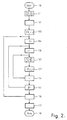
- the method for determining the Compton profiles is now explained in more detail below on the basis of the flow diagram shown in FIG. 2.
- the detector 6 provides a set of measured values T (r, ⁇ ) which are a measure of the transmission on the radiation path as a function of the distance r of this radiation path from the center of the examination area 4 and of the angle ⁇ at which the radiation path covers the examination region enforced.
- the detector l0 provides a set of measured values M (E, r, ß), which also depends on r and, but also on the energy E of the scattered radiation.
- the attenuation distribution in the plane of the examination area 4, through which the primary beam passes, is determined from the measured values T (r, ⁇ ) (block 10).
- the reconstruction methods required for this are well known to the person skilled in computer tomography, so that there is no need to go into detail about them.
- the scattering coefficient S (E, x, y) is specified.
- the scattering coefficient represents the product of the scattering density and the differential scattering cross section related to the solid angle detected by the detector l0 and to the respective energy range (El, E2 ... Et).
- the scattering coefficient of a pixel would be directly that of the detector l0 and the pulse height analyzer l2 up to l4 delivered measured value for the relevant energy range proportional - if in Examination area outside the pixel would not be scattered.
- the position of a radiation path is specified in which the angle ⁇ is specified, at which the radiation path passes through the examination area (block l04), and in which the distance r of the radiation path from the center of the examination area is specified (block l05).
- the coordinates x (r, ß) and y (r, ß) of the pixels are then determined in a Cartesian xy coordinate system, the origin of which coincides with the center space of the examination area and the y axis of which is intersected by the beam path at an angle, that lie on the radiation path in the examination area (block l06).
- a correction value is then formed (block l07) for the pixels which lie on the beam path defined by r and ⁇ and for each of the energy areas, which is added to the stored value of the scattering coefficient for the same energy area and the same pixel. This correction value is chosen so that the deviation between the predetermined value of the scattering coefficient and the actual value is reduced. How this happens is explained below with reference to FIG. 3.
- S is the scattering coefficient
- Fp is the attenuation that the primary beam experiences on the beam path up to the respective pixel (ie the fraction of the primary radiation that reaches the pixel)
- Fs the attenuation that is the scattered radiation emanating from the pixel to the detector l0 experiences (ie the proportion of the scattered radiation generated in the pixel and running in the direction of the detector l0, which reaches the detector l0)
- c a constant which is independent of the examination area 4 and which is only dependent on the properties of the rest of the device (e.g.
- the factor Fp can be taken directly from the computer tomogram previously calculated (block l02), since the weakening of the pixels lying on the radiation path between the pixel in question and the radiation source is known.
- the factor Fs cannot be taken directly from the tomogram because the quantum energy of the scattered radiation is significantly lower than that of the primary radiation; If, for example, the quantum energy in the primary beam is 412 keV, then the maximum of the Compton scattering results for a scattering angle of 155 ° Energy of about 162.4 keV. Scattered radiation with so much lower energy is weakened much more than the energy of the primary radiation.
- the secondary radiation is weakened the attenuation in the computer tomogram if the attenuation values in the pixels lying between the relevant pixel and the second detector 10 are multiplied by a constant factor.
- the factor corresponds to the total scattering cross section for the energy of the scattered radiation divided by the total scattering cross section for the energy of the primary beam.
- the calculation of the total scattering cross sections for different energies is known from the literature (for example Hubbel "Photon Cross Sections, Attenuation Coefficients ", published in August 1969 by the National Bureau of Standards). For the specified scattered radiation series, this factor is approximately 1.4.
- the Correction value K determined in this way is divided by the number of pixels on the radiation path and added with a weighting factor a, which is less than one, to the value S specified for the pixel in question xy and the energy concerned (block ll2).
- the value formed in this way comes closer to the actual value than the initially specified value.
- a new radiation path is then determined by the value r, i.e. the distance of the radiation path from the center of the examination area 4 is varied (block II4), so that a radiation path adjacent and parallel to the previous radiation path is specified.
- steps l06 ... ll3 are repeated, after which the next radiation path is specified, etc., until the correction has been made for all the radiation paths passing through the examination area at an angle.
- step ll5 A different direction of the radiation paths is then specified (step ll5) and steps l05 to ll4 are repeated until all the angular positions at which the primary beam has passed through the examination area during the measurement have been processed.
- This iteration can then be followed (block ll6) by further iterations, with steps l04 to ll5 being carried out several times. A fixed number of iterations can be provided. However, it is also possible to stop the iteration when the corrections have been made (Block III) always fall below a certain threshold. Then there is a corrected distribution S (E, x, y) which corresponds to the actual distribution to a good approximation.
- the measured values determined as a function of the energy in step 10l for the individual radiation paths can also be specified as a function of the momentum transfer.
- the scattering coefficients for the individual pixels are then specified as a function of the impulse transfer, after which the described conversion of the scattered radiation spectrum into a Compton profile in block ll7 can be omitted.
Applications Claiming Priority (2)
| Application Number | Priority Date | Filing Date | Title |
|---|---|---|---|
| DE19863630651 DE3630651A1 (de) | 1986-09-09 | 1986-09-09 | Verfahren zur zweidimensionalen compton-profil-abbildung |
| DE3630651 | 1986-09-09 |
Publications (2)
| Publication Number | Publication Date |
|---|---|
| EP0259921A2 true EP0259921A2 (fr) | 1988-03-16 |
| EP0259921A3 EP0259921A3 (fr) | 1990-02-21 |
Family
ID=6309210
Family Applications (1)
| Application Number | Title | Priority Date | Filing Date |
|---|---|---|---|
| EP87201638A Withdrawn EP0259921A3 (fr) | 1986-09-09 | 1987-08-31 | Procédé pour formation en 2 dimensions des images de profil Compton |
Country Status (4)
| Country | Link |
|---|---|
| US (1) | US4850002A (fr) |
| EP (1) | EP0259921A3 (fr) |
| JP (1) | JPS6370153A (fr) |
| DE (1) | DE3630651A1 (fr) |
Families Citing this family (24)
| Publication number | Priority date | Publication date | Assignee | Title |
|---|---|---|---|---|
| US5070455A (en) * | 1989-11-22 | 1991-12-03 | Singer Imaging, Inc. | Imaging system and method using scattered and diffused radiation |
| US5430787A (en) * | 1992-12-03 | 1995-07-04 | The United States Of America As Represented By The Secretary Of Commerce | Compton scattering tomography |
| US5963658A (en) * | 1997-01-27 | 1999-10-05 | University Of North Carolina | Method and apparatus for detecting an abnormality within a host medium |
| US5841141A (en) * | 1997-06-03 | 1998-11-24 | The University Of Utah | Image reconstruction from V-projections acquired by Compton camera |
| US5861627A (en) * | 1997-06-24 | 1999-01-19 | The University Of Utah | Image reconstruction for compton camera including spherical harmonics |
| US7006676B1 (en) | 2000-01-21 | 2006-02-28 | Medical Optical Imaging, Inc. | Method and apparatus for detecting an abnormality within a host medium utilizing frequency-swept modulation diffusion tomography |
| CA2348150C (fr) | 2000-05-25 | 2007-03-13 | Esam M.A. Hussein | Systeme non rotatif a rayons x pour l'imagerie tridimensionnelle et triparametrique |
| US6563906B2 (en) | 2000-08-28 | 2003-05-13 | University Of New Brunswick | X-ray compton scattering density measurement at a point within an object |
| US7203276B2 (en) * | 2004-08-27 | 2007-04-10 | University Of New Brunswick | X-ray scatter image reconstruction by balancing of discrepancies between detector responses, and apparatus therefor |
| US7319733B2 (en) * | 2004-09-27 | 2008-01-15 | General Electric Company | System and method for imaging using monoenergetic X-ray sources |
| US20080226019A1 (en) * | 2005-07-07 | 2008-09-18 | Koninklijke Philips Electronics, N.V. | Multiple Scatter Correction |
| US20080219404A1 (en) * | 2007-03-08 | 2008-09-11 | Bio-Imaging Research, Inc. | Method and Apparatus to Facilitate Formation of a Two-Dimensional Image Using X-Ray Fan Beam Scatter |
| US20080253527A1 (en) * | 2007-04-11 | 2008-10-16 | Searete Llc, A Limited Liability Corporation Of The State Of Delaware | Limiting compton scattered x-ray visualizing, imaging, or information providing at particular regions |
| US20080253522A1 (en) * | 2007-04-11 | 2008-10-16 | Searete Llc, A Limited Liability Corporation Of The State Of Delaware | Tool associated with compton scattered X-ray visualization, imaging, or information provider |
| US20080253627A1 (en) * | 2007-04-11 | 2008-10-16 | Searete LLC, a limited liability corporation of | Compton scattered X-ray visualization, imaging, or information provider using image combining |
| US8041006B2 (en) * | 2007-04-11 | 2011-10-18 | The Invention Science Fund I Llc | Aspects of compton scattered X-ray visualization, imaging, or information providing |
| US8837677B2 (en) * | 2007-04-11 | 2014-09-16 | The Invention Science Fund I Llc | Method and system for compton scattered X-ray depth visualization, imaging, or information provider |
| US7711089B2 (en) * | 2007-04-11 | 2010-05-04 | The Invention Science Fund I, Llc | Scintillator aspects of compton scattered X-ray visualization, imaging, or information providing |
| US20080253525A1 (en) * | 2007-04-11 | 2008-10-16 | Boyden Edward S | Compton scattered x-ray visualizing, imaging, or information providing of at least some dissimilar matter |
| US8488902B2 (en) * | 2009-01-29 | 2013-07-16 | Koninklijke Philips Electronics N.V. | Detection values correction apparatus |
| EP2488104A1 (fr) * | 2009-10-13 | 2012-08-22 | Koninklijke Philips Electronics N.V. | Dispositif et méthode d'élaboration d'images contrastées de tissus mous |
| JP5403423B2 (ja) * | 2009-11-04 | 2014-01-29 | 株式会社Ihi | 高エネルギーx線のエネルギー弁別検査装置と検査方法 |
| EP3663749A1 (fr) * | 2018-12-07 | 2020-06-10 | Siemens Healthcare GmbH | Système et procédé d'imagerie par rayons x |
| JP7223993B2 (ja) * | 2019-02-27 | 2023-02-17 | 株式会社トプコン | 非破壊検査システム及び非破壊検査方法 |
Citations (2)
| Publication number | Priority date | Publication date | Assignee | Title |
|---|---|---|---|---|
| EP0011897A1 (fr) * | 1978-11-27 | 1980-06-11 | Laboratoires D'electronique Et De Physique Appliquee L.E.P. | Appareil d'examen tomographique par exploration de milieux aux rayons X ou gamma |
| GB2054319A (en) * | 1979-06-30 | 1981-02-11 | Philips Nv | Method of and device for determining the contour of a body by means of radiation scattered by the body |
Family Cites Families (1)
| Publication number | Priority date | Publication date | Assignee | Title |
|---|---|---|---|---|
| DE2944147A1 (de) * | 1979-11-02 | 1981-05-14 | Philips Patentverwaltung Gmbh, 2000 Hamburg | Anordnung zur ermittlung der streudichteverteilung in einem ebenen untersuchungsbereich |
-
1986
- 1986-09-09 DE DE19863630651 patent/DE3630651A1/de not_active Withdrawn
-
1987
- 1987-08-31 EP EP87201638A patent/EP0259921A3/fr not_active Withdrawn
- 1987-09-03 US US07/092,805 patent/US4850002A/en not_active Expired - Fee Related
- 1987-09-07 JP JP62222155A patent/JPS6370153A/ja active Pending
Patent Citations (2)
| Publication number | Priority date | Publication date | Assignee | Title |
|---|---|---|---|---|
| EP0011897A1 (fr) * | 1978-11-27 | 1980-06-11 | Laboratoires D'electronique Et De Physique Appliquee L.E.P. | Appareil d'examen tomographique par exploration de milieux aux rayons X ou gamma |
| GB2054319A (en) * | 1979-06-30 | 1981-02-11 | Philips Nv | Method of and device for determining the contour of a body by means of radiation scattered by the body |
Non-Patent Citations (2)
| Title |
|---|
| IEEE TRANSACTIONS ON NUCLEAR SCIENCE, Band NS-33, Nr. 1, Februar 1986, Seiten 531-536, IEEE, New York, US; B.W. LOO et al.: "A new compton densitometer for measuring pulmonary edema" * |
| TRANSACTION OF THE AMERICAN NUCLEAR SOCIETY, Band 47, 1984, Seiten 38-39; S. ANGHAIE et al.: "Atomic composition measurement in Vivo using compton profile methods" * |
Also Published As
| Publication number | Publication date |
|---|---|
| US4850002A (en) | 1989-07-18 |
| DE3630651A1 (de) | 1988-03-17 |
| JPS6370153A (ja) | 1988-03-30 |
| EP0259921A3 (fr) | 1990-02-21 |
Similar Documents
| Publication | Publication Date | Title |
|---|---|---|
| EP0259921A2 (fr) | Procédé pour formation en 2 dimensions des images de profil Compton | |
| DE2733586C2 (fr) | ||
| EP0242895B1 (fr) | Procédé pour la détermination de la structure spatiale dans une couche de la zone examinée | |
| EP0153786B1 (fr) | Appareil à rayons X | |
| DE102006017290B4 (de) | Fokus/Detektor-System einer Röntgenapparatur, Röntgen-System und Verfahren zur Erzeugung von Phasenkontrastaufnahmen | |
| DE102006063048B3 (de) | Fokus/Detektor-System einer Röntgenapparatur zur Erzeugung von Phasenkontrastaufnahmen | |
| DE60132556T2 (de) | Röntgeninspektionssystem mit gefiltertem strahl | |
| EP0571017B1 (fr) | Procédé de filtrage pour un système rayons X et agencement pour réaliser ledit procédé de filtrage | |
| EP0209952B1 (fr) | Procédé pour la mesure de la répartition spatiale de rayonnement X diffusé élastiquement ainsi que le dispositif pour la mise en oeuvre du procédé | |
| DE69931096T2 (de) | Vorrichtung und Verfahren für zwei-Energien Röntgenstrahlungs-Bilderzeugung | |
| DE102005027436B4 (de) | Verfahren zur Berechnung von absorberspezifischen Gewichtungskoeffizienten und Verfahren zur Verbesserung eines von einem Absorber abhängigen Kontrast-zu-Rausch-Verhältnisses in einem von einer Röntgeneinrichtung erzeugten Röntgenbild eines zu untersuchenden Objektes | |
| DE102011004598B4 (de) | Verfahren und Computersystem zur Streustrahlkorrektur in einem Multi-Source-CT | |
| DE2916486A1 (de) | Korrektur polychromatischer roentgenbildfehler in computertomographiebildern | |
| DE2730324C2 (de) | Computer-Tomograph | |
| DE2753004A1 (de) | Beseitigung spektraler kuenstlicher effekte und benutzung spektraler effekte bei der computerisierten tomographie | |
| DE2544354A1 (de) | Verfahren zur bestimmung der dichte von koerpern mittels durchdingender strahlen und geraet zu seiner durchfuehrung | |
| DE10036142A1 (de) | Röntgen-Computertomographieeinrichtung | |
| DE2704784C2 (de) | Computer-Tomograph | |
| EP1774301A2 (fr) | Tomographe a rayons x assiste par ordinateur ainsi que procede pour examiner une piece a controler a l'aide d'un tomographe a rayons x assiste par ordinateur | |
| DE102004022332A1 (de) | Verfahren zur post-rekonstruktiven Korrektur von Aufnahmen eines Computer-Tomographen | |
| DE2831038C2 (de) | Strahlendiagnostikgerät für die Erzeugung von Schichtbildern | |
| DE2702009A1 (de) | Radiographisches geraet | |
| DE2130841A1 (de) | Verfahren zum tomographischen Untersuchen von radioaktiv gemachten Orangen und Vorrichtung zum Durchfuehren dieses Verfahrens | |
| DE2831311C2 (de) | Vorrichtung zur Ermittlung innerer Körperstrukturen mittels Streustrahlung | |
| EP0217464B1 (fr) | Procédé pour la détermination de l'atténuation photonique dans un domaine d'un corps et dispositif pour la mise en oeuvre du procédé |
Legal Events
| Date | Code | Title | Description |
|---|---|---|---|
| PUAI | Public reference made under article 153(3) epc to a published international application that has entered the european phase |
Free format text: ORIGINAL CODE: 0009012 |
|
| AK | Designated contracting states |
Kind code of ref document: A2 Designated state(s): DE FR GB NL |
|
| PUAL | Search report despatched |
Free format text: ORIGINAL CODE: 0009013 |
|
| AK | Designated contracting states |
Kind code of ref document: A3 Designated state(s): DE FR GB NL |
|
| STAA | Information on the status of an ep patent application or granted ep patent |
Free format text: STATUS: THE APPLICATION IS DEEMED TO BE WITHDRAWN |
|
| 18D | Application deemed to be withdrawn |
Effective date: 19900822 |
|
| RIN1 | Information on inventor provided before grant (corrected) |
Inventor name: KOSANETZKY, JOSEF-MARIE, DR. Inventor name: NEITZEL, ULRICH, DR. Inventor name: HARDING, GEOFFREY, DR. |