EP0570231A1 - Ensemble de stator d'un moteur plat - Google Patents
Ensemble de stator d'un moteur plat Download PDFInfo
- Publication number
- EP0570231A1 EP0570231A1 EP93303727A EP93303727A EP0570231A1 EP 0570231 A1 EP0570231 A1 EP 0570231A1 EP 93303727 A EP93303727 A EP 93303727A EP 93303727 A EP93303727 A EP 93303727A EP 0570231 A1 EP0570231 A1 EP 0570231A1
- Authority
- EP
- European Patent Office
- Prior art keywords
- stator
- stator core
- flat motor
- coil
- armature coil
- Prior art date
- Legal status (The legal status is an assumption and is not a legal conclusion. Google has not performed a legal analysis and makes no representation as to the accuracy of the status listed.)
- Granted
Links
Images


Classifications
-
- H—ELECTRICITY
- H02—GENERATION; CONVERSION OR DISTRIBUTION OF ELECTRIC POWER
- H02K—DYNAMO-ELECTRIC MACHINES
- H02K3/00—Details of windings
- H02K3/46—Fastening of windings on the stator or rotor structure
- H02K3/52—Fastening salient pole windings or connections thereto
- H02K3/521—Fastening salient pole windings or connections thereto applicable to stators only
- H02K3/522—Fastening salient pole windings or connections thereto applicable to stators only for generally annular cores with salient poles
-
- H—ELECTRICITY
- H02—GENERATION; CONVERSION OR DISTRIBUTION OF ELECTRIC POWER
- H02K—DYNAMO-ELECTRIC MACHINES
- H02K3/00—Details of windings
- H02K3/32—Windings characterised by the shape, form or construction of the insulation
- H02K3/325—Windings characterised by the shape, form or construction of the insulation for windings on salient poles, such as claw-shaped poles
-
- H—ELECTRICITY
- H02—GENERATION; CONVERSION OR DISTRIBUTION OF ELECTRIC POWER
- H02K—DYNAMO-ELECTRIC MACHINES
- H02K3/00—Details of windings
- H02K3/32—Windings characterised by the shape, form or construction of the insulation
- H02K3/34—Windings characterised by the shape, form or construction of the insulation between conductors or between conductor and core, e.g. slot insulation
- H02K3/345—Windings characterised by the shape, form or construction of the insulation between conductors or between conductor and core, e.g. slot insulation between conductor and core, e.g. slot insulation
-
- H—ELECTRICITY
- H02—GENERATION; CONVERSION OR DISTRIBUTION OF ELECTRIC POWER
- H02K—DYNAMO-ELECTRIC MACHINES
- H02K2203/00—Specific aspects not provided for in the other groups of this subclass relating to the windings
- H02K2203/03—Machines characterised by the wiring boards, i.e. printed circuit boards or similar structures for connecting the winding terminations
-
- H—ELECTRICITY
- H02—GENERATION; CONVERSION OR DISTRIBUTION OF ELECTRIC POWER
- H02K—DYNAMO-ELECTRIC MACHINES
- H02K2203/00—Specific aspects not provided for in the other groups of this subclass relating to the windings
- H02K2203/12—Machines characterised by the bobbins for supporting the windings
Definitions
- the present invention relates to a flat motor stator, which provides especially simple construction of armature coil insulation, and furthermore relates to the very easy assembly of the flat motor stator.
- the newest tape recorders, photocopiers and other electronic apparatus follow a trend to downsizing and lighter height for requirements from user and improvement of capacity and requirements.
- a bobbin is provided for the pole But since the motor is made smaller and flatter, this bobbin can not be fitted on the magnetic pole. Then thick synthetic resin membranes are adhered to the whole stator instead of the bobbin. Or sometimes tapes are affixed to the magnetic poles. As a result, there is not enough space to wind the armature coil winding on the magnetic poles, so that the coil can not have many windings
- Another object of the present invention is to provide a stator unit with a flat motor which has a sufficient insulation gap between the armature coil and each of magnetic pole when the wound coil is finished.
- Still another abject of the present invention is to provide a stator unit with a flat motor which obtains ampere turn of the armature coil as much as possible.
- last another object of the present invention is to provide a stator unit with a flat motor which makes it easier for the assembly due to forming flatter forms in comparison with the conventional one.
- the flat motor has the armature coil insulation and forms in flat construction, moreover, the coil does not loosen at the time of assembly.
- Fig.1 is a cross-sectional view of an auto-rotor type flat motor relating to the present invention.
- 1 denotes a motor base plate made form a printed circuit board.
- axle 2 is installed in the centre of the motor base plate.
- an auto-rotor 5 rotates freely on the axle through bearings 3 and 4.
- Auto-rotor 5 is shaped like turning a thin flat circular platter over and in its centre bearing 6 is installed.
- bearings 3 and 4 are arranged on the inside of the outer wall 7 of auto-rotor 5, a ring shaped magnet 8 made of ferrite is installed.
- stator core 12 equipped with a plurality of magnetic poles 10 having the multiple poles 11 protuding circularly from the outside wall is arranged.
- the stator core 12 is made up from yoku 9, magnetic pole 10 and poll 11 with 3 layers of silicon-steel sheets.
- the armature coil 13 is wound around the magnetic coil 10 ( a drawing is not shown). The construction of stator core 12, which is included in the armature coil 13 will be discussed later.
- electronic equipment 14 needed to drive the motor is arranged in the free space between bearing 6 and yoke 9 of stator core 12.
- aformentioned stator core 12 may be made with ferrite, however composition with silicon-stel sheet is also suitable.
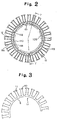
- Fig.2 shows a front view of stator core 12 not wound flat motor coil retating the present invention.
- the stator core 12 is made up from yoke 9, magnetic poles 10 and poles 11 laminated with 3 layers of silicon-street sheet 17 as a core shown in Fig.3.
- yoke 9 is covered with the inside frame 130 made of synthetic resin. The both side surfaces of magnetic pole 10 is adhered at the same time with thin layer insulation 133 of said insert-moule-process.
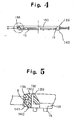
- Fig.4 shows a cross-sectional view cut along the Y-Y line in Fig.2.
- Fig.5 shows an enlarged cross-sectional view of the part cirecled by the two-dotted line in Fig.4.
- Fig.6 shows the bottom view of stator core 12.
- the flat outside support 139 (in illustration 2 the slanted section) on the surface of inner frame 130 forms at the same time the outside edge 136. This outside edge 136 connects one magnetic pole with the next magnetic pole as a lead wire.
- the flat inner support 140 is provided (slanted area in Fig. 6).
- fins 131 provided on the inside of frame 130 is arranged toward the center direction.
- the inner frame 130 is equipped with small holes, penetrating from its upper to its lower surface, and the T-shaped pins 138 as the terminals of armature coil 13 are formed as they are inlaid.
- 15 denotes a boss protruded on the flat inside support 140 of inner frame 130, which are for determining position for previously mentioned motor base plate 1.
- the outer ledge 141 for the same purpose of the outre ledge 136 are formed.
- grooves 142 are formed toward the surface of inner periphery from the surface of outer periphery of inner frame 130.
- These grooves 142 match equally deep ones on the surface of flat inner holder 140. These grooves 142 provide a path for the terminals of the armature coil 13. The outlets of the small holes 132 on the inner surface of stator core 12 form the terminal inserts 143 which are in laid into the L-shaped pins 138.
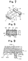
- Fig.7 is a partially perspective view shown 1 magnetic pole of stator core 12.
- Fig.8 shows a cross-sectional view of Fig.7 cut along line A-A.
- thin insulation layer 133 is formed at the time of the insert-mould process on both sides of magnetic pole 10.
- the vertical hight D form the thickness of magnetic pole 10 is for example 0.2 mm greater.
- the upper and lower parts of the surface of magnetic pole 10 stand out, and it is available that this part is covered with an insulation membrane 133 and 134 of a thickness of at least 0.1 mm by electro-plating. That thickness protruding from the inner and outer surface of magnetic pole 10 is sufficiently small from the hight of part (D-d)/2.
- Armature coil 13 is wound on every magnetic poles 10. In the embodiment, for example, 4 poles each are successively wound. Begining and end of the coils are driven through previously mentioned small holes 132 each of which is connected by coiling around pins 138. Under these circumstances, the outer edge 136 of the lower part of previously mentioned inner frame 130 is a path of connected leads between adjoin armature coils 13, and also grooves 137 of inner frame 130 as shown in Fig.6 is a path which the beginning and end of coils are wired to pins 138.
- armature coils 13 at the end of tbe winding process is applied for preventing loosening of the winding varnish, andsince the coil wire's lead wire is routed on the lower part of inner frame 130 and join the end of the coil wire through the groove to pin 138, very durable armature coils can be obtained.
- small holes 16 are provided to insert boss 15 (for positioning and hooking of stator core 12) in base plate 1. These small holes 16 are provided for positioning and installation of stator core 12.
- the boss 15 of stator core 12 are inserted in the samall holes 16 of motor base plate 1 combined with electronic parts. Possibly after glueing or melting the face of hub 15, stator core 12 adhers to base plate 1 and installation of electrical wiring, which the tip of armature coil is installed to motor base plate 1 and the terminal is connected, is carried out.
- the axle 6 of auto-rotor 5 is inserted into the bearings 2, and with the fitting of C-ring 100 (Fig.1) on the tip of axle 2, the assembly of the motor is completed.
- the hubs 15 are located on top of the flat inside support of the inner surface of stator core 12, however it is also possible that as shown in Fig.9, on the flat inner surface support 140, a groove 144 having a little wide groove connected to the outer surface from the inner surface of stator core 12 is formed, and an elongated hub 150 is installed inside of the groove 144ted by a groove 144 and hub 150 is utilized for positioning as well as for booking of armature coil terminal 145.
- insulation is installed on the outer surface of the magnetic pole, and the magnetic pole is thicker than the electrode. Because of this, when the armature coil of the magnetic pole is wound, the armature coil is constructed such that the wire does not touch the corners of the magnetic pole. Accordingly, the wire is prevented from touching and the magnetic pole thin layer installation does not break down and the wire is also not directly in contact with the inner or outer surface. Therefore, although the stator core is sufficiently thin, it can be secured that there is sufficient insulation space between the magnetic pole gap and the armature coil. Furthermore the beginning and end of the aramture coil winding are coiled around pins, so that the armature coil will not loosen when longitudinal pulling force occurs. Consequently the motor assembly becomes much simplier.
Landscapes
- Engineering & Computer Science (AREA)
- Power Engineering (AREA)
- Insulation, Fastening Of Motor, Generator Windings (AREA)
- Curing Cements, Concrete, And Artificial Stone (AREA)
Applications Claiming Priority (2)
| Application Number | Priority Date | Filing Date | Title |
|---|---|---|---|
| JP14875292A JPH05319952A (ja) | 1992-05-14 | 1992-05-14 | 連通多孔質体 |
| JP148752/92 | 1992-05-15 |
Publications (2)
| Publication Number | Publication Date |
|---|---|
| EP0570231A1 true EP0570231A1 (fr) | 1993-11-18 |
| EP0570231B1 EP0570231B1 (fr) | 1997-01-15 |
Family
ID=15459842
Family Applications (1)
| Application Number | Title | Priority Date | Filing Date |
|---|---|---|---|
| EP19930303727 Expired - Lifetime EP0570231B1 (fr) | 1992-05-14 | 1993-05-14 | Ensemble de stator d'un moteur plat |
Country Status (3)
| Country | Link |
|---|---|
| EP (1) | EP0570231B1 (fr) |
| JP (1) | JPH05319952A (fr) |
| DE (1) | DE69307386T2 (fr) |
Cited By (2)
| Publication number | Priority date | Publication date | Assignee | Title |
|---|---|---|---|---|
| EP0951132A2 (fr) * | 1998-04-18 | 1999-10-20 | Abb Research Ltd. | Barre d'enroulement pour machine électrique de haute tension et procédé pour la fabrication d'une telle barre |
| EP0978930A1 (fr) * | 1998-08-07 | 2000-02-09 | Hitachi Metals, Ltd. | Générateur à aimant permanent pour disquette et disquette intégrant ce générateur |
Families Citing this family (4)
| Publication number | Priority date | Publication date | Assignee | Title |
|---|---|---|---|---|
| JP2607396Y2 (ja) * | 1993-04-16 | 2001-07-09 | 株式会社三協精機製作所 | ブラシレスモータ |
| JPH10322944A (ja) | 1997-05-19 | 1998-12-04 | Minebea Co Ltd | モータ構造及びその製造方法 |
| JP5098484B2 (ja) * | 2007-07-25 | 2012-12-12 | 宇部興産株式会社 | 窯業建材用多孔質材料、窯業建材およびそれらの製造方法 |
| DE102010038789A1 (de) | 2010-08-02 | 2012-02-02 | Robert Bosch Gmbh | Elektromotor |
Citations (6)
| Publication number | Priority date | Publication date | Assignee | Title |
|---|---|---|---|---|
| US3122667A (en) * | 1961-05-25 | 1964-02-25 | Gen Electric | Laminated magnetic core for use in an electric inductive device |
| US3339097A (en) * | 1965-08-10 | 1967-08-29 | Eastman Mfg Co Inc | Bobbin and pole construction |
| DE2021916A1 (de) * | 1970-05-05 | 1971-11-25 | Licentia Gmbh | Im Spritzverfahren hergestellte Isolationsauskleidung fuer Nuten |
| EP0015244A1 (fr) * | 1979-02-27 | 1980-09-03 | Eta A.G. Ebauches-Fabrik | Procédé de fabrication de stators pour moteurs pas à pas de montres électroniques, et moteur réalisé selon le procédé |
| US4554491A (en) * | 1984-08-10 | 1985-11-19 | Msl Industries, Inc. | Brushless DC motor having a laminated stator with a single stator winding |
| US4910420A (en) * | 1988-07-27 | 1990-03-20 | Nidec Corporation | Brushless electric motor |
-
1992
- 1992-05-14 JP JP14875292A patent/JPH05319952A/ja active Pending
-
1993
- 1993-05-14 DE DE1993607386 patent/DE69307386T2/de not_active Expired - Fee Related
- 1993-05-14 EP EP19930303727 patent/EP0570231B1/fr not_active Expired - Lifetime
Patent Citations (6)
| Publication number | Priority date | Publication date | Assignee | Title |
|---|---|---|---|---|
| US3122667A (en) * | 1961-05-25 | 1964-02-25 | Gen Electric | Laminated magnetic core for use in an electric inductive device |
| US3339097A (en) * | 1965-08-10 | 1967-08-29 | Eastman Mfg Co Inc | Bobbin and pole construction |
| DE2021916A1 (de) * | 1970-05-05 | 1971-11-25 | Licentia Gmbh | Im Spritzverfahren hergestellte Isolationsauskleidung fuer Nuten |
| EP0015244A1 (fr) * | 1979-02-27 | 1980-09-03 | Eta A.G. Ebauches-Fabrik | Procédé de fabrication de stators pour moteurs pas à pas de montres électroniques, et moteur réalisé selon le procédé |
| US4554491A (en) * | 1984-08-10 | 1985-11-19 | Msl Industries, Inc. | Brushless DC motor having a laminated stator with a single stator winding |
| US4910420A (en) * | 1988-07-27 | 1990-03-20 | Nidec Corporation | Brushless electric motor |
Non-Patent Citations (2)
| Title |
|---|
| PATENT ABSTRACTS OF JAPAN vol. 7, no. 99 (E-172)(1244) 27 April 1983 & JP-A-58 22 553 ( HITACHI ) 9 February 1983 * |
| PATENT ABSTRACTS OF JAPAN vol. 8, no. 49 (E-230)(1486) 6 March 1984 & JP-A-58 201 553 ( MATSUSHITA ) 24 November 1983 * |
Cited By (3)
| Publication number | Priority date | Publication date | Assignee | Title |
|---|---|---|---|---|
| EP0951132A2 (fr) * | 1998-04-18 | 1999-10-20 | Abb Research Ltd. | Barre d'enroulement pour machine électrique de haute tension et procédé pour la fabrication d'une telle barre |
| EP0951132A3 (fr) * | 1998-04-18 | 2002-01-09 | Alstom | Barre d'enroulement pour machine électrique de haute tension et procédé pour la fabrication d'une telle barre |
| EP0978930A1 (fr) * | 1998-08-07 | 2000-02-09 | Hitachi Metals, Ltd. | Générateur à aimant permanent pour disquette et disquette intégrant ce générateur |
Also Published As
| Publication number | Publication date |
|---|---|
| DE69307386D1 (de) | 1997-02-27 |
| DE69307386T2 (de) | 1997-05-15 |
| JPH05319952A (ja) | 1993-12-03 |
| EP0570231B1 (fr) | 1997-01-15 |
Similar Documents
| Publication | Publication Date | Title |
|---|---|---|
| US5508578A (en) | Stator unit of flat motor | |
| US4745388A (en) | Transformer with wire lead isolation slots | |
| US9197102B2 (en) | Stator assembly for motor having hall sensor part fixed to end of tooth of stator | |
| EP0622970B1 (fr) | Bobine mobile et structure de haut-parleur | |
| EP0570231B1 (fr) | Ensemble de stator d'un moteur plat | |
| JP2002325385A (ja) | 回転界磁型電気機器のステータ構造 | |
| JPH0870544A (ja) | ステータコアの絶縁構造 | |
| JPH07135745A (ja) | 電動機のコア | |
| JP3819989B2 (ja) | 電磁モータの巻線絶縁構造 | |
| JP2002186203A (ja) | 電機子およびその電機子を用いたモータ | |
| JPH0555521U (ja) | 変圧器の構造 | |
| JP2876236B2 (ja) | 電動機の電機子 | |
| JPH08316040A (ja) | シートトランスおよびその製造方法 | |
| JPH09322453A (ja) | ステータコア | |
| JP3130092B2 (ja) | 電動機の固定子 | |
| JPH0521950Y2 (fr) | ||
| KR960013545B1 (ko) | 정류자 전동기용 고정자 절연장치 | |
| JPS5826259B2 (ja) | 小型直流モ−タおよびその製造方法 | |
| JPS5886851A (ja) | 平面対向型モ−タの電機子コイル | |
| JP2553582B2 (ja) | コンデンサ電動機の固定子 | |
| WO1995009474A1 (fr) | Bobine de champ pour moteur | |
| JP2002281707A (ja) | 電磁モータの巻線絶縁構造 | |
| JPH0723029Y2 (ja) | ステツピングモ−タ | |
| JP2022018593A (ja) | 回転電機のステータの結線板、回転電機のステータ、回転電機、回転電機のステータの結線板の製造方法、回転電機のステータの製造方法および回転電機の製造方法 | |
| JP2984046B2 (ja) | 同軸型ロータリートランスの製造方法 |
Legal Events
| Date | Code | Title | Description |
|---|---|---|---|
| PUAI | Public reference made under article 153(3) epc to a published international application that has entered the european phase |
Free format text: ORIGINAL CODE: 0009012 |
|
| AK | Designated contracting states |
Kind code of ref document: A1 Designated state(s): DE FR GB IT |
|
| 17P | Request for examination filed |
Effective date: 19940510 |
|
| 17Q | First examination report despatched |
Effective date: 19950531 |
|
| GRAG | Despatch of communication of intention to grant |
Free format text: ORIGINAL CODE: EPIDOS AGRA |
|
| GRAH | Despatch of communication of intention to grant a patent |
Free format text: ORIGINAL CODE: EPIDOS IGRA |
|
| GRAH | Despatch of communication of intention to grant a patent |
Free format text: ORIGINAL CODE: EPIDOS IGRA |
|
| GRAA | (expected) grant |
Free format text: ORIGINAL CODE: 0009210 |
|
| RAP1 | Party data changed (applicant data changed or rights of an application transferred) |
Owner name: MINEBEA CO.,LTD. |
|
| AK | Designated contracting states |
Kind code of ref document: B1 Designated state(s): DE FR GB IT |
|
| ITF | It: translation for a ep patent filed |
Owner name: BUZZI, NOTARO&ANTONIELLI D'OULX |
|
| ET | Fr: translation filed | ||
| REF | Corresponds to: |
Ref document number: 69307386 Country of ref document: DE Date of ref document: 19970227 |
|
| PLBE | No opposition filed within time limit |
Free format text: ORIGINAL CODE: 0009261 |
|
| STAA | Information on the status of an ep patent application or granted ep patent |
Free format text: STATUS: NO OPPOSITION FILED WITHIN TIME LIMIT |
|
| 26N | No opposition filed | ||
| REG | Reference to a national code |
Ref country code: GB Ref legal event code: IF02 |
|
| GBPC | Gb: european patent ceased through non-payment of renewal fee |
Effective date: 20030514 |
|
| REG | Reference to a national code |
Ref country code: GB Ref legal event code: 728V |
|
| REG | Reference to a national code |
Ref country code: GB Ref legal event code: 728Y |
|
| PGFP | Annual fee paid to national office [announced via postgrant information from national office to epo] |
Ref country code: IT Payment date: 20080528 Year of fee payment: 16 |
|
| PGFP | Annual fee paid to national office [announced via postgrant information from national office to epo] |
Ref country code: GB Payment date: 20080514 Year of fee payment: 16 |
|
| PGFP | Annual fee paid to national office [announced via postgrant information from national office to epo] |
Ref country code: DE Payment date: 20090511 Year of fee payment: 17 |
|
| GBPC | Gb: european patent ceased through non-payment of renewal fee |
Effective date: 20090514 |
|
| REG | Reference to a national code |
Ref country code: FR Ref legal event code: ST Effective date: 20100129 |
|
| PG25 | Lapsed in a contracting state [announced via postgrant information from national office to epo] |
Ref country code: FR Free format text: LAPSE BECAUSE OF NON-PAYMENT OF DUE FEES Effective date: 20090602 |
|
| PGFP | Annual fee paid to national office [announced via postgrant information from national office to epo] |
Ref country code: FR Payment date: 20080514 Year of fee payment: 16 |
|
| PG25 | Lapsed in a contracting state [announced via postgrant information from national office to epo] |
Ref country code: GB Free format text: LAPSE BECAUSE OF NON-PAYMENT OF DUE FEES Effective date: 20090514 |
|
| PG25 | Lapsed in a contracting state [announced via postgrant information from national office to epo] |
Ref country code: IT Free format text: LAPSE BECAUSE OF NON-PAYMENT OF DUE FEES Effective date: 20090514 |
|
| PG25 | Lapsed in a contracting state [announced via postgrant information from national office to epo] |
Ref country code: DE Free format text: LAPSE BECAUSE OF NON-PAYMENT OF DUE FEES Effective date: 20101201 |