EP0568798B9 - Aus Baugruppen zusammengesetztes Bearbeitungszentrum - Google Patents
Aus Baugruppen zusammengesetztes Bearbeitungszentrum Download PDFInfo
- Publication number
- EP0568798B9 EP0568798B9 EP93104144A EP93104144A EP0568798B9 EP 0568798 B9 EP0568798 B9 EP 0568798B9 EP 93104144 A EP93104144 A EP 93104144A EP 93104144 A EP93104144 A EP 93104144A EP 0568798 B9 EP0568798 B9 EP 0568798B9
- Authority
- EP
- European Patent Office
- Prior art keywords
- machining
- axis
- tools
- cell according
- unit
- Prior art date
- Legal status (The legal status is an assumption and is not a legal conclusion. Google has not performed a legal analysis and makes no representation as to the accuracy of the status listed.)
- Expired - Lifetime
Links
Images














Classifications
-
- B—PERFORMING OPERATIONS; TRANSPORTING
- B23—MACHINE TOOLS; METAL-WORKING NOT OTHERWISE PROVIDED FOR
- B23Q—DETAILS, COMPONENTS, OR ACCESSORIES FOR MACHINE TOOLS, e.g. ARRANGEMENTS FOR COPYING OR CONTROLLING; MACHINE TOOLS IN GENERAL CHARACTERISED BY THE CONSTRUCTION OF PARTICULAR DETAILS OR COMPONENTS; COMBINATIONS OR ASSOCIATIONS OF METAL-WORKING MACHINES, NOT DIRECTED TO A PARTICULAR RESULT
- B23Q37/00—Metal-working machines, or constructional combinations thereof, built-up from units designed so that at least some of the units can form parts of different machines or combinations; Units therefor in so far as the feature of interchangeability is important
-
- B—PERFORMING OPERATIONS; TRANSPORTING
- B23—MACHINE TOOLS; METAL-WORKING NOT OTHERWISE PROVIDED FOR
- B23Q—DETAILS, COMPONENTS, OR ACCESSORIES FOR MACHINE TOOLS, e.g. ARRANGEMENTS FOR COPYING OR CONTROLLING; MACHINE TOOLS IN GENERAL CHARACTERISED BY THE CONSTRUCTION OF PARTICULAR DETAILS OR COMPONENTS; COMBINATIONS OR ASSOCIATIONS OF METAL-WORKING MACHINES, NOT DIRECTED TO A PARTICULAR RESULT
- B23Q1/00—Members which are comprised in the general build-up of a form of machine, particularly relatively large fixed members
-
- B—PERFORMING OPERATIONS; TRANSPORTING
- B23—MACHINE TOOLS; METAL-WORKING NOT OTHERWISE PROVIDED FOR
- B23Q—DETAILS, COMPONENTS, OR ACCESSORIES FOR MACHINE TOOLS, e.g. ARRANGEMENTS FOR COPYING OR CONTROLLING; MACHINE TOOLS IN GENERAL CHARACTERISED BY THE CONSTRUCTION OF PARTICULAR DETAILS OR COMPONENTS; COMBINATIONS OR ASSOCIATIONS OF METAL-WORKING MACHINES, NOT DIRECTED TO A PARTICULAR RESULT
- B23Q11/00—Accessories fitted to machine tools for keeping tools or parts of the machine in good working condition or for cooling work; Safety devices specially combined with or arranged in, or specially adapted for use in connection with, machine tools
- B23Q11/0042—Devices for removing chips
- B23Q11/0067—Devices for removing chips chip containers located under a machine or under a chip conveyor
-
- B—PERFORMING OPERATIONS; TRANSPORTING
- B23—MACHINE TOOLS; METAL-WORKING NOT OTHERWISE PROVIDED FOR
- B23Q—DETAILS, COMPONENTS, OR ACCESSORIES FOR MACHINE TOOLS, e.g. ARRANGEMENTS FOR COPYING OR CONTROLLING; MACHINE TOOLS IN GENERAL CHARACTERISED BY THE CONSTRUCTION OF PARTICULAR DETAILS OR COMPONENTS; COMBINATIONS OR ASSOCIATIONS OF METAL-WORKING MACHINES, NOT DIRECTED TO A PARTICULAR RESULT
- B23Q11/00—Accessories fitted to machine tools for keeping tools or parts of the machine in good working condition or for cooling work; Safety devices specially combined with or arranged in, or specially adapted for use in connection with, machine tools
- B23Q11/08—Protective coverings for parts of machine tools; Splash guards
-
- B—PERFORMING OPERATIONS; TRANSPORTING
- B23—MACHINE TOOLS; METAL-WORKING NOT OTHERWISE PROVIDED FOR
- B23Q—DETAILS, COMPONENTS, OR ACCESSORIES FOR MACHINE TOOLS, e.g. ARRANGEMENTS FOR COPYING OR CONTROLLING; MACHINE TOOLS IN GENERAL CHARACTERISED BY THE CONSTRUCTION OF PARTICULAR DETAILS OR COMPONENTS; COMBINATIONS OR ASSOCIATIONS OF METAL-WORKING MACHINES, NOT DIRECTED TO A PARTICULAR RESULT
- B23Q7/00—Arrangements for handling work specially combined with or arranged in, or specially adapted for use in connection with, machine tools, e.g. for conveying, loading, positioning, discharging, sorting
- B23Q7/03—Arrangements for handling work specially combined with or arranged in, or specially adapted for use in connection with, machine tools, e.g. for conveying, loading, positioning, discharging, sorting by means of endless chain conveyors
-
- Y—GENERAL TAGGING OF NEW TECHNOLOGICAL DEVELOPMENTS; GENERAL TAGGING OF CROSS-SECTIONAL TECHNOLOGIES SPANNING OVER SEVERAL SECTIONS OF THE IPC; TECHNICAL SUBJECTS COVERED BY FORMER USPC CROSS-REFERENCE ART COLLECTIONS [XRACs] AND DIGESTS
- Y10—TECHNICAL SUBJECTS COVERED BY FORMER USPC
- Y10S—TECHNICAL SUBJECTS COVERED BY FORMER USPC CROSS-REFERENCE ART COLLECTIONS [XRACs] AND DIGESTS
- Y10S29/00—Metal working
- Y10S29/056—Metal working with shield or hood movements
-
- Y—GENERAL TAGGING OF NEW TECHNOLOGICAL DEVELOPMENTS; GENERAL TAGGING OF CROSS-SECTIONAL TECHNOLOGIES SPANNING OVER SEVERAL SECTIONS OF THE IPC; TECHNICAL SUBJECTS COVERED BY FORMER USPC CROSS-REFERENCE ART COLLECTIONS [XRACs] AND DIGESTS
- Y10—TECHNICAL SUBJECTS COVERED BY FORMER USPC
- Y10T—TECHNICAL SUBJECTS COVERED BY FORMER US CLASSIFICATION
- Y10T29/00—Metal working
- Y10T29/51—Plural diverse manufacturing apparatus including means for metal shaping or assembling
- Y10T29/5104—Type of machine
- Y10T29/5109—Lathe
- Y10T29/5114—Lathe and tool
-
- Y—GENERAL TAGGING OF NEW TECHNOLOGICAL DEVELOPMENTS; GENERAL TAGGING OF CROSS-SECTIONAL TECHNOLOGIES SPANNING OVER SEVERAL SECTIONS OF THE IPC; TECHNICAL SUBJECTS COVERED BY FORMER USPC CROSS-REFERENCE ART COLLECTIONS [XRACs] AND DIGESTS
- Y10—TECHNICAL SUBJECTS COVERED BY FORMER USPC
- Y10T—TECHNICAL SUBJECTS COVERED BY FORMER US CLASSIFICATION
- Y10T408/00—Cutting by use of rotating axially moving tool
- Y10T408/91—Machine frame
-
- Y—GENERAL TAGGING OF NEW TECHNOLOGICAL DEVELOPMENTS; GENERAL TAGGING OF CROSS-SECTIONAL TECHNOLOGIES SPANNING OVER SEVERAL SECTIONS OF THE IPC; TECHNICAL SUBJECTS COVERED BY FORMER USPC CROSS-REFERENCE ART COLLECTIONS [XRACs] AND DIGESTS
- Y10—TECHNICAL SUBJECTS COVERED BY FORMER USPC
- Y10T—TECHNICAL SUBJECTS COVERED BY FORMER US CLASSIFICATION
- Y10T409/00—Gear cutting, milling, or planing
- Y10T409/30—Milling
- Y10T409/30392—Milling with means to protect operative or machine [e.g., guard, safety device, etc.]
-
- Y—GENERAL TAGGING OF NEW TECHNOLOGICAL DEVELOPMENTS; GENERAL TAGGING OF CROSS-SECTIONAL TECHNOLOGIES SPANNING OVER SEVERAL SECTIONS OF THE IPC; TECHNICAL SUBJECTS COVERED BY FORMER USPC CROSS-REFERENCE ART COLLECTIONS [XRACs] AND DIGESTS
- Y10—TECHNICAL SUBJECTS COVERED BY FORMER USPC
- Y10T—TECHNICAL SUBJECTS COVERED BY FORMER US CLASSIFICATION
- Y10T409/00—Gear cutting, milling, or planing
- Y10T409/30—Milling
- Y10T409/309576—Machine frame
-
- Y—GENERAL TAGGING OF NEW TECHNOLOGICAL DEVELOPMENTS; GENERAL TAGGING OF CROSS-SECTIONAL TECHNOLOGIES SPANNING OVER SEVERAL SECTIONS OF THE IPC; TECHNICAL SUBJECTS COVERED BY FORMER USPC CROSS-REFERENCE ART COLLECTIONS [XRACs] AND DIGESTS
- Y10—TECHNICAL SUBJECTS COVERED BY FORMER USPC
- Y10T—TECHNICAL SUBJECTS COVERED BY FORMER US CLASSIFICATION
- Y10T483/00—Tool changing
- Y10T483/16—Tool changing with means to transfer work
-
- Y—GENERAL TAGGING OF NEW TECHNOLOGICAL DEVELOPMENTS; GENERAL TAGGING OF CROSS-SECTIONAL TECHNOLOGIES SPANNING OVER SEVERAL SECTIONS OF THE IPC; TECHNICAL SUBJECTS COVERED BY FORMER USPC CROSS-REFERENCE ART COLLECTIONS [XRACs] AND DIGESTS
- Y10—TECHNICAL SUBJECTS COVERED BY FORMER USPC
- Y10T—TECHNICAL SUBJECTS COVERED BY FORMER US CLASSIFICATION
- Y10T483/00—Tool changing
- Y10T483/17—Tool changing including machine tool or component
- Y10T483/1702—Rotating work machine tool [e.g., screw machine, lathe, etc.]
- Y10T483/1705—Tool support comprises rotary spindle
-
- Y—GENERAL TAGGING OF NEW TECHNOLOGICAL DEVELOPMENTS; GENERAL TAGGING OF CROSS-SECTIONAL TECHNOLOGIES SPANNING OVER SEVERAL SECTIONS OF THE IPC; TECHNICAL SUBJECTS COVERED BY FORMER USPC CROSS-REFERENCE ART COLLECTIONS [XRACs] AND DIGESTS
- Y10—TECHNICAL SUBJECTS COVERED BY FORMER USPC
- Y10T—TECHNICAL SUBJECTS COVERED BY FORMER US CLASSIFICATION
- Y10T483/00—Tool changing
- Y10T483/17—Tool changing including machine tool or component
- Y10T483/1702—Rotating work machine tool [e.g., screw machine, lathe, etc.]
- Y10T483/1714—Tool changer between tool support and matrix
- Y10T483/1719—Tool support comprises turret
-
- Y—GENERAL TAGGING OF NEW TECHNOLOGICAL DEVELOPMENTS; GENERAL TAGGING OF CROSS-SECTIONAL TECHNOLOGIES SPANNING OVER SEVERAL SECTIONS OF THE IPC; TECHNICAL SUBJECTS COVERED BY FORMER USPC CROSS-REFERENCE ART COLLECTIONS [XRACs] AND DIGESTS
- Y10—TECHNICAL SUBJECTS COVERED BY FORMER USPC
- Y10T—TECHNICAL SUBJECTS COVERED BY FORMER US CLASSIFICATION
- Y10T483/00—Tool changing
- Y10T483/17—Tool changing including machine tool or component
- Y10T483/1733—Rotary spindle machine tool [e.g., milling machine, boring, machine, grinding machine, etc.]
- Y10T483/179—Direct tool exchange between spindle and matrix
- Y10T483/1793—Spindle comprises tool changer
- Y10T483/1795—Matrix indexes selected tool to transfer position
-
- Y—GENERAL TAGGING OF NEW TECHNOLOGICAL DEVELOPMENTS; GENERAL TAGGING OF CROSS-SECTIONAL TECHNOLOGIES SPANNING OVER SEVERAL SECTIONS OF THE IPC; TECHNICAL SUBJECTS COVERED BY FORMER USPC CROSS-REFERENCE ART COLLECTIONS [XRACs] AND DIGESTS
- Y10—TECHNICAL SUBJECTS COVERED BY FORMER USPC
- Y10T—TECHNICAL SUBJECTS COVERED BY FORMER US CLASSIFICATION
- Y10T74/00—Machine element or mechanism
- Y10T74/21—Elements
- Y10T74/219—Guards
Definitions
- the invention relates to a processing cell composed of assemblies.
- a machining center is previously known from DE-OS-40 12 690.
- This machining center consists of a bed carrying a workpiece table, a slide that can be moved longitudinally on the bed, a stand that can be moved transversely on the slide, a machining head that can be moved vertically on the stand, and a tool magazine with changer, the bed being a sloping bed that slopes backwards, the workpiece table is placed at the front of the bed.
- brackets for attaching a table bracket and at least one chip shaft are provided on the vertical front of the inclined bed.
- the stand has two rigid pillars rigidly connected to one another by at least one crosshead, with vertical guides on the inside, on which the machining head is guided on both sides.
- Various processing heads can be optionally mounted on the stand.
- At the front of the stand there is an accompanying chip apron on which the chips slide into this chip shaft.
- the chip apron is designed like a blind and is attached to the bed with its lower end, the processing head being laterally displaceable at its upper end.
- Various tool tables with their brackets can be mounted on the bed.
- the tool magazine with its tool changer are arranged in a stationary manner, the tool changer being started by a movement of the inclined slide.
- DE-OS 38 24 602 relates to a machine for machining cubic and rotationally symmetrical workpieces (parts), with machining groups for the various operations such as drilling, milling and turning operations, are assigned to a machine base frame in a modular manner, that is to say the individual machining or Modules can be omitted or retrofitted.
- a rotating unit is designed as a workpiece clamping unit with a positionable axis, which brings the workpiece to the respective processing unit in any required position.
- Workpiece clamping unit and machining units are designed for five-sided machining of a workpiece and are assigned to one another.
- the turning unit is equipped with an automatic or a manually operated workpiece clamping device, whereby a main spindle of the turning unit, the design of which makes both feeds for operations such as milling and drilling operations and higher speeds for operations possible.
- a processing unit with two tool systems can also be present.
- the processing unit has adjustment options in the X, Y and Z directions as the first tool system a rotating one Working spindle for holding drilling and milling tools and as a second tool system a multiple turret, preferably one known per se Twelve or sixteen revolvers, for holding stationary or adjustable driven tools, on. It can also be used as a second main spindle Counter spindle of a first main spindle is provided his. It is also a tool changer for those Work spindle available.
- the machining center with automatic or programmable Workpiece changing devices should be provided. There may also be a tool breakage check be with a central chip disposal.
- DE-PS 34 16 660 is a lathe with work spindle arranged vertically in the headstock, with drive motor attached to the headstock, with at the lower end of the work spindle arranged workpiece chuck and with below the tool spindle arranged on the work spindle previously known, the headstock in vertical and horizontal direction is movable, the vertical and horizontal movement stroke on the one hand the feed for filming and on the other hand for Movement of the chuck to a laterally arranged one horizontal workpiece feed and removal station serves.
- the pick-up method is from this publication previously known.
- DE-PS 27 39 087 describes a machine tool with an indexable that can be rotated on a bed and in the longitudinal direction of the bed movable workpiece table, one across the Crossbeams running along the bed, supported on columns, one on the crossbar in a horizontal direction sliding carriage, one on the carriage in vertically arranged slidably Tool carrier, at its lower end pivotable about a horizontal axis, in different Tool holder lockable with swivel positions a tool spindle is attached, in which means a clamping device a rotationally drivable tool can be used with a motor and gear train existing rotary drive for the tool spindle, with a possibility of optional mounting a fixed turning tool at the lower end area of the tool holder, and with a tool magazine and an automatic Tool changer.
- the tool holder can be another, fixed tool holder with a clamping device assigned to it provided for receiving the fixed turning tool be the pivoting tool holder directly on one side surface of the tool carrier attached next to the fixed tool holder and in a pivot position parallel to this is automatically lockable, in which the rotatable Tool through which also to replace the fixed Tool changer provided is interchangeable, in which the fixed turning tool at the same time in the fixed arranged tool holder and in the swivel Tool holder is clamped, and that the two Clamping devices can be operated automatically synchronously are.
- WO-A-85/03 893 shows a processing machine with a horizontal base plate, two vertical stands, spaced apart and parallel to each other protrude upwards in the form of plates that pass through at their rear end areas lower and upper stiffeners are connected.
- the stands are used for Inclusion of two horizontal trunnions that form an axis around one Can swivel motor-driven swivel unit.
- An upper wall of the Swivel unit is also used to hold a turntable, which by one on the Swivel unit arranged axis of rotation is drivable. It will on the turntable Workpiece to be machined clamped.
- the axis of rotation of the turntable is over a Belt drive driven by a gear motor unit.
- the angular position of the Swivel unit around its horizontal axis is controlled by a motor unit and determined that acts on the journal of the swivel unit gear. In this way the swivel unit can be swiveled.
- This sled points to its Front a horizontal guide on which horizontal and parallel to Swing axis of the swivel unit, another slide slidably and over a Ball screw is arranged drivable by one on the carriage in question arranged motor is driven.
- the sled itself has vertical guides, on which a milling head can be moved vertically via a ball screw spindle, which is driven by a motor arranged on the carriage.
- the milling head carries a spindle running in the vertical axis, on which the milling tool is located, the spindle being driven in rotation by a motor via a belt transmission becomes.
- On the main slide is in a corresponding vertical guide additional housing support arranged.
- This case support is in the vertical direction along an axis at the same distance between the two stands by a rack and pinion and slidable, the rack is driven by a motor on the main support concerned.
- the case support carries a vertical axis in the same equidistant plane of the two Stand and is at its lower end with a housing for holding tools, such as turning tools or drilling tools, provided by the housing support can be positioned so that the execution of the desired processing is possible.
- a workpiece is to be machined, then this clamped on the turntable by means of conventional fastening, where then the Turntable is rotated at a certain angle about its axis of rotation when one Drilling is to be carried out.
- the swivel axis can also be used be pivoted through a predetermined angle. In this way, the workpiece be brought into the desired geometric position, the hanging Milling head is moved with its tool into an appropriate position for machining perform.
- the turntable can be changed the angular position of the swivel unit at its required speed Rotational axis are rotatably driven.
- the swivel unit remains for drilling in its vertical position while the rotary table is being rotated, the in maintains its horizontal position in this case.
- the control of the various Motor units, both the positioning and the execution of the machining can serve in a conventional manner, e.g. B. done by hand.
- the processing machine can also be used for a numerical Control is suitable. This previously known processing machine makes it possible to carry out milling, turning and drilling work.
- EP-A-0 088 645 shows a numerically controlled machine tool with vertical hanging main spindle.
- the spindle is mounted in a quill and is supported by a separate, top-mounted motor driven while moving towards the Z-axis by a separate motor arranged on the side of a slide he follows.
- Both the motor for driving in the Z axis and the motor for driving the main spindle are on a kind of vertically extending, columnar pedestal arranged that in a horizontal direction on a motor in opposite
- the slide which can be moved in directions, rests on the right and left of the columnar platform magazines for tools and workpieces are either by the main spindle itself or by a to the side of the Main spindle arranged and driven by another motor gripper system be brought into the respective position.
- the drive in the Y direction takes place again by another motor, which is also arranged on the columnar platform is.
- the entire processing machine is open on all sides, wherein the carriage is arranged on a flat base plate.
- the ones to be processed Workpieces and the tools are in magazines side by side on the sliding Sledge unit arranged.
- Another motor drives that over a rod Chuck. This publication requires a wide, large footprint for the magazines, for workpieces and tools, for the horizontal slide unit and for the towering podium.
- the headstock is in the X and Z axes with the turret support fixed movable.
- the headstock is built on a cross slide and with a horizontal one Axis of rotation and has a drive motor integrated in the headstock.
- the Cross slide is mounted on a horizontal rail guide, which in turn is on a double rail guide offset by 90 ° is arranged.
- US-A-4 534 686 shows a motor spindle underlying the problem, a particular one To create cooling system to direct heat conduction from the stator of the Motor to exclude the front part of the spindle.
- the invention is based on the object To design the machining center so that simple, but also complicated processing machines, even if they are linked to transfer lines or flexible manufacturing systems is desired, simple to build and have it manufactured relatively cheaply.
- the invention allows a processing cell build in modules.
- the vertically arranged Spindle unit with two axes up to five axes can both tool headstock and workpiece headstock his.
- a processing cell according to the invention is suitable for drilling, turning, milling, measuring, hardening, Welding for symmetrical or asymmetrical, cylindrical or cubic parts, preferably for so-called Chuck parts.
- a particular advantage of the proposed according to the invention Machining cell can be seen in the fact that this means that the main components are cheaply prefabricated and to the desired processing machines can be assembled economically.
- This enables a modular design with significant reduction in manufacturing costs. For example this way, NC-controlled lathes, Machining centers, machining cells or manufacture linked systems, their manufacturing costs around a very substantial amount below the manufacturing costs conventional systems, for example only with the Half of the previous manufacturing costs.
- the drive with the main spindle is a unit as so-called motor spindle.
- the main spindle and drive arranged concentrically to each other and thus enable a compact design.
- the drive z. B. by a highly dynamic frequency-controlled maintenance-free three-phase motor.
- a high Stiffness of the spindle is ensured by precision bearings reached.
- angular contact ball bearings at the front and Cylindrical roller bearings at the rear are special here Advantage. All bearings are grease lubricated for life Mistake. Thanks to the thermosymmetrical structure of the headstock and cooling system results in a practically constant accuracy. Another embodiment can also be used with hydrostatic bearings be equipped.
- the tool loading and unloading station can be at the Front (operator side) into the processing machine to get integrated. This can also be done in a simple manner include in the machining center according to the invention.
- a possible tool and / or workpiece change can be carried out directly from the pick-up sled by placing the carriage in the loading and unloading position. picks up the existing tool and again emits.
- the delivery position can be in the work area or in the buffer - outside of it - in the area of the measuring station.
- Partitions or doors between the work area, Loading and unloading station and between measuring and Tool storage stations enable extensive dirt-tight separation of these rooms from each other.
- An automatic tool change can be easily included in the processing cell the preferred tool wear or works during the changeover, but usually not during the processing.
- a pick-up lathe manufactured then in addition to the turning operations also quick workpiece or tool changes To run.
- only one simple, inexpensive workpiece feed and removal belt needed in the kit in the loading and unloading station can be included.
- Through programming of the cross slide (pick-up spindle) can Tool parameters for loading and unloading the workpieces to be used. All movements to Loading and unloading the spindle, for machining and to measure the workpieces with the pick-up spindle executed.
- the machining center according to the invention also allows a consistent separation of loading and Unloading station, work area and measuring zone. This separation of the three areas prevents swarf problems when loading and unloading the workpieces or when measuring.
- the hanging workpieces contribute to an optimal chip drain.
- a simple, quick tool change will achieved by clearing the work area with the Cross slide.
- the door between the loading zone and For this purpose, the work area is completely lowered.
- the basic machine body included in the machining cell guaranteed from reaction resin concrete best thermal stability and excellent damping properties.
- Reactive resin concrete has against about six to eight times better than gray cast iron Damping behavior.
- the torsion-resistant construction makes a usually required machine foundation superfluous. The machine can thus the normal hall floor.
- the large distance between the two high-precision linear guides ensures high turning precision in the X-axis.
- the tours are also outside the Work area and therefore do not require covers against pollution.
- the headstock unit with cross slide is e.g. B. biaxial (X and Z). Short off-times are used when changing workpieces and tools Approach of the probe compared to conventional training due to short travel distances and high rapid traverse speed reached.
- Three-phase motors used to drive the cross slide. They drive the sledge via high-precision ball screws.
- X, Y and Z are encapsulated measuring systems. The guidance and measuring systems are located outside the work area.
- the slide guide systems are designed for. B. with high-precision preloaded linear roller guides; whose coefficient of friction is significantly lower than at conventional sliding guides.
- This system guarantees in the processing cell according to the invention, for Example of a CNC controlled lathe, one Machining cell or one cell highest turning precision and high dynamics.
- the cross slide with main spindle is in all Axes with suspended energy supplies equipped. They are simple, maintenance-free and placed outside the chip area what contributes to a further simplification of the kit.
- the work area is through the two side panels of the reaction resin concrete body, by two Doors and through a movable with the headstock Cover plate completely from the loading and unloading zone as well as separated from the measuring zone and is against sealed the leakage of coolant lubricants and chips.
- the machine covers, for example, a CNC-controlled machine Lathe with a protective device
- Aluminum slats cover the entire front.
- the slats are provided with windows and slits.
- the window ensure insight into that for the Machine operation important areas.
- An easy one Direct access to the axis drives is through the cover in the side walls and at the top of the automatic lathes given.
- a cooling unit controls the heat balance of the Machine, for example a CNC controlled lathe, which according to a machining center the invention is constructed.
- the spindle bearings and the spindle drive are at constant temperatures held.
- the tool measurement takes place e.g. B. with a probe mounted on the headstock.
- To the button moves when changing a cutting edge to measure from its cover. After measuring the actual values are calculated directly in the control.
- the next workpiece is thus within a predetermined one Tolerance edited.
- a chip conveyor can be located below the main body be provided for after chip disposal serve to the left or right of the machine or to the rear.
- a chip pan can also be used or a flat chip wagon to slide in in the machine base from left to right or from the front of the machine.
- An extractor can also be installed in the assembly for coolant mist extraction from the work area be included.
- An assembly according to the invention can be used special advantage for the production of lathes use for lining parts. Under lining parts Turned parts understood without additional Support on the side facing away from the chuck Page can be machined.
- the workpiece storage to be included in the assembly and conveyor belt with a loading and unloading station can be carried out without retrofitting.
- the pick-up spindle can put the finished parts here, after which the Band continues and the spindle the next blank grasps.
- the belt can be used as a chain timing belt with transport prisms be carried out.
- the distance of the Align the transport prisms and thus the storage capacity according to the chuck diameter used (large chuck diameter large distance between the transport prisms).
- the storage capacity can be, for example, 25 workpieces.
- the workpieces are taken over for the pick-up spindle positioned accordingly.
- different Workpiece heights are defined in the NC part program.
- a good workpiece system in the clamping device is through a pressing unit in the conveyor belt ensures. To do this, use the pick-up spindle against the sprung Pressure unit driven.
- Also in the assembly or in the processing cell can be a converter for moving the workpieces from one conveyor belt to another be involved.
- a workpiece converter with a turning unit be included in the processing cell, for simultaneous turning and moving of workpieces machined on one side.
- the machine base Since the machine base the work area encloses, results in a compact design.
- the machine base can thereby perform several functions, namely support the processing machine to be formed to Example of a lathe on the hall floor without an additional foundation, wearing the Headstock unit with cross slide and motor spindle and to carry the storage and transport unit as well as to shield and enclose the work area with the necessary parts.
- the machining cell according to claim 3 the guides for the Cross slide on the top of the machine base arranged.
- the machine control receiving container-like space as at Machine base of attached energy container educated. This opens up the possibility the energy container to the required extent before assembling with the other components, for example with the machine base, in appropriately connected.
- the embodiment according to claim 5 contributes to a compact construction.
- the motor spindle engages with its Spindle attachment in the vertical direction a sheet metal cover, so that no pollution escapes to the outside can.
- An embodiment according to claim 7 contributes to an automatic quality control of the machined parts, such as lining parts.
- the machine base encloses the work area from at least three sides, namely on the opposite vertical side walls and the vertical back wall and from below, that is from Ground. This results in a closed, encapsulated Construction, whereby also any sound and Odor emissions are largely prevented.
- the machine base constructed from a suitable reactive resin concrete. This results in an excellent one thermal stability with excellent damping properties.
- This form can, for example, according to claim 15 come about in that under one Machine base body feet are arranged to the machine base for the purpose of transportation and for installation in a suitable place by means of a forklift or the like is easier to transport. These feet can be made removable be for transportation in low workshops.
- the Feet also allow a chip conveyor to be inserted or chip car into the machine of all four Pages.
- the base body forms through its H or U shape a stable basis for the assemblies.
- the guides of the cross slide are on top put on the side walls. Between the guide walls sit in the upper part of the "H” or the "U” the mounting bases for the tool system and the probe.
- the recesses, especially in the area of chips and coolants are through a shaped sheet that is lost Mold in the reaction resin concrete body is poured, protected.
- the cast sheet shape protects the base body in the area of chips and coolant. There are more cutouts for that Return of the storage and transport belt at a possible variant is provided.
- the H or U shape allows the guides of the Cross slide far forward over the machining position protract. This results in a stable Basis for the multifunctional sledge.
- the machine cover is a solid sheet, at the bottom of the cross slide fastens and seals the work area from the top.
- This cross slide carries on one end Vertical guides spaced apart or rails on which the motor spindle unit in vertical Adjustable direction between the vertical ones Walls of the machine base is arranged. Is the machine body in cross section H or U-shaped, then the longitudinal axis runs the motor spindle unit in a range between the vertical webs or walls of the machine body. This also contributes to a compact structure the machine.
- the in the processing cell according to the invention included energy container can be a self-supporting Sheet metal construction to be carried out completely pre-assembled on the fully assembled Basic machine, consisting of basic body, motor spindle, Cross slide and tool system, attached becomes.
- the energy container is used with just a few Screws attached.
- the energy container contains the fully installed control cabinet with led out pre-assembled connections to the consumers.
- the individual cables are in flatbeds laid and hang down in loops and lead to moving consumers with whom they are connected by plugs.
- the cooling unit is on the control cabinet Spindle and cabinet cooling and below that Hydraulics or air supply arranged.
- the water, hydraulic or air hoses are like the electrical cables in swings or loops for Consumer led.
- the energy container will be on Finish assembling the basic machine like one Body connected to the basic machine in the car. The consumers are connected and the The machine is practically ready for operation.
- Claim 18 describes a preferred Embodiment of a processing cell for production a lathe.
- Claim 29 describes a processing cell to build a four-axis, multifunctional Machining system for machining workpieces with three-axis, multifunctional cross slide, with a spindle unit with C-axis and transverse Double turret or multiple tool holder bar.
- the double revolver has standing and rotating tools.
- Claim 30 describes a processing cell to build a six-axis, multifunctional Machining system for complete machining a workpiece in two setups with three-axis, multifunctional cross slide, with a spindle unit with a C-axis and a lower one, multifunctional work unit and with an E-axis for swiveling and with a spindle unit with F-axis.
- From claim 31 is a processing cell to build a seven-axis, multifunctional Machining system for complete machining of a Workpiece in two setups with four-axis, multifunctional cross slide with D-axis, with a spindle unit with C-axis and one lower, multi-functional work unit with an E-axis for swiveling and a spindle unit with F-axis.
- the processing cell can be combined Workpiece and tool clamping device added his. This is used within the multifunctional upper and lower work units from a centrically exciting Multi-jaw chuck or any special chuck with a central tool holder. Both clamping devices (tools and chucks) are operated via a pull rod. A protective cap prevents when used as Tool clamp the pollution of the Workpiece clamping jaws. This will make a chuck and combined a tool holder with each other, a pull rod actuates both.
- the processing cell can also by a lower multifunctional work unit with several fixed tools and an off-center Work spindle to be supplemented.
- the whole unit swivels CNC-controlled and the work spindle can thus in its swivel axis (E-axis) in any one Working angles.
- the work spindle becomes stepless from a built-in or external AC motor driven.
- the work spindle can be a combined one Workpiece and tool clamping device to choose from Pick up tools and workpieces own
- the work spindle has a CNC controlled Axis (F-axis).
- the combination is a full Working spindle with a multiple disc turret given on one axis.
- the off-center mounted work spindle enables the use of a Attachment spindle with a favorable short Z stroke. It is a combined use of the work spindle is possible, and this spindle can be used as a workpiece carrier and once be provided as a tool carrier.
- this can processed from the opposite feed and brought to a correspondingly high accuracy.
- machining center in the machining center according to the invention can be a storage belt with a conveyor belt for workpieces and integrate tools.
- workpieces can take prism, pallets, the part shape are adjusted or clamping pallets or other part-dependent Carriers are used.
- tool pallets For tools there is the option of tool pallets to equip with tools that face down and can stand on top.
- the belts can be single or double, arranged in parallel or individually to the Machine around, forwards or through the machine be arranged through.
- the conveyor belt is being set up by simply adjusting the drive to the respective part diameter set.
- the tools are on the storage and Conveyor belt provided in interchangeable pallets.
- pallets themselves are used instead of workpieces put on the tape by the prism chain centered and clocked.
- the tool gripper on the multifunctional Cross slide takes hold of the first worn tool out of the tool holder and put it in the first empty one Tool holder pallet on the storage tape.
- the tools that are not preset are selected by one also exchangeable in the upper work unit or existing measuring probe.
- the Tool dimensions are automatically in the machine control stored.
- a calibration pen replaced in place of a tool and be measured with the probe being the new basic position of the tool holder is stored in the machine data.
- tool carrier systems are also integrated.
- a block steel holder can be placed on the Basic body instead of a multiple disc turret, Find application.
- Revolvers can be placed on the base body with swivel axis running parallel to the X axis use, as a multiple disc turret with different tool holder systems, short swiveling times thanks to three-phase servo motor with directional logic. Furthermore such for stationary tools for turning and drilling, rolling and so on, or for powered tools in some stations for turning, drilling, milling etc.
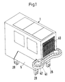
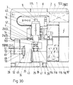
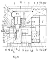
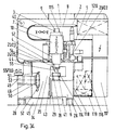
- Figure 1 is one of a the kit described below in detail built processing machine in application a CNC-controlled machining cell 1, also machining center called, illustrated.
- This kit essentially consists of an energy container 2, a motor spindle 3, one Sheet metal cover 4, a cross slide 5 and one Machine base 6.
- the energy container 2 is a self-supporting sheet metal construction trained to be fully pre-assembled on the fully assembled basic machine put on and with few screws is attached.
- the energy container 2 contains the fully installed control cabinet with pre-assembled connections to consumers.
- the individual cables 7 and the hydraulic and / or air supply lines (Fig. 3 and 20) are laid in platforms 8 and hang in Loops down so that they can follow the movements of the Motor spindle 3 and the cross slide 5 are able to follow.
- the cables 7 are with the individual consumers connected by plug so that the couplings can be released very quickly, but can also be restored.
- control cabinet Cooling unit for spindle and control cabinet cooling provided while under the Control cabinet the hydraulic and air supply is located (not shown).
- the water, hydraulic or Air hoses (not shown) are like the electrical cables 7 led in loops to the consumers as described in connection with the cables 7 has been.
- the energy container 2 is at the end of the assembly like a body in a car with the basic machine connected, so that it can be seen in FIG apparent exterior results. After that, consumers connected and the machine is practical operational. This results in a very time-saving inexpensive process with minimal material consumption.
- the motor spindle 3 consists of one in detail not shown, concentrically surrounding the spindle 9 Motor 10 in the illustrated embodiment a highly dynamic frequency controlled maintenance-free three-phase spindle motor with, for example 10/16 kW cutting power at 100/40% ED.
- the motor spindle 3 is in a carrier unit 11 arranged, the plate-shaped and over several ribs 12, 13 in one piece with the motor housing is connected (Fig. 2, 3).
- the carrier unit 11 is with two pairs The same-sized guide shoes are spaced from each other 14, 15 or 16, 17 by screws or the like firmly connected and on guide rails 18, 19 of the cross slide 5 guided in the vertical plane.
- FIGS. 2 and 3 is the headstock unit from motor spindle 3 and cross slide 5, biaxial executed.
- the stroke is 560 mm. short Non-productive times when changing tools and starting of the probe are also here by a high Rapid traverse speed reached.
- thermosymmetric structure of the headstock unit 3, 5 Due to the thermosymmetric structure of the headstock unit 3, 5 and by a cooling system yourself a constant accuracy.
- the cross slide 5 is activated by a fast, frequency-controlled, maintenance-free three-phase motor driven. This drive drives the Cross slide 5 via high-precision ground ball screws on.
- This drive drives the Cross slide 5 via high-precision ground ball screws on.
- the cross slide 5 has spaced, equally large guide shoes 20, 21, 22 and 23 on ( Figure 2).
- the guide shoes 20 to 23 are with the body of the cross slide 5 by screws or the like in one piece, but detachable, connected.
- the guide shoes 20, 21 and 22, 23 are on parallel and spaced guide rails 24 and 25 out. Both of these guides for the cross slide 5 as well as the guides 18 and 19 for the carrier unit 11 with motor spindle 3 with the guide shoes 14, 15, 16 and 17 z. B. with high-precision, preloaded linear roller guides be provided, the coefficient of friction more than ten times is lower than with conventional sliding guides. This system guarantees high turning precision and high Dynamics.
- the motor spindle 3 and the cross slide 5 are in both axes with hanging energy supplies equipped. They are simply structured maintenance-free and arranged outside the chip area.
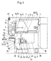
- the base body 6 consists of reaction resin concrete and in particular from FIGS. 3 and 4 embodiment shown in one by its longitudinal axis, orthogonal cross section has an H shape and thus has a stable base for the attached assemblies, i.e. for the energy container 2, the motor spindle 3, the sheet metal cover 4 and the cross slide 5.
- the base body 6 stands on four machine feet 28, which are arranged in the corner regions of the base body 6 and the z. B. for the transport of the machine a forklift or the like in low Factory halls and can be unscrewed through gates.
- the cutouts, especially in the chips and coolant area, are through a shaped sheet 29, which is lost Form in the reaction resin concrete of the Base body 6 is cast, protected.
- Two further recesses 30 and 31 are for the Return of the not shown in Figures 1 to 3 Storage and conveyor belt at a possible Variant provided (Fig. 19 and 20).
- the guide rails 24 and 25 are on the top the vertical and parallel to each other Side walls 26 and 27 of the base body 6 arranged.
- a working space 34 and a measuring zone 35 are from the U-legs forming side walls 26 and 27 and of which the side walls 26 and 27 material integrally connecting, facing the ground Web 37 and one with the side walls 26 and 27 also integrally connected rear wall 38 (Fig. 2) enclosed. This is through the body 6 space formed only upwards and forwards open. This room is raised by the cross slide 5 covered with the sheet metal cover 4 while at the front a loading and unloading zone 39 is arranged with a roller blind 40.
- the base body 6 also serves as a fixed unit in the manner described below for receiving tool carriers and turrets. This allows long tool life to be expected; for example 30 to 50 % more than before.
- the base body 6 enables the following described attachment of a multifunctional lower work unit or a double turret in the two side walls 26 and 27 a simple workspace cover with little Space requirements depending on the maximum to be processed Workpiece dimensions.
- the H shape allows the guide rails 24 and 25 of the cross slide 5 far forward over the Pull out the machining position. This results in a stable basis for the multifunctional sled.
- the machine cover consists of the fixed sheet metal cover 4, which is attached to the cross slide 5 below and a well-closed work space 34 completes above.
- the molded sheet 29 protects the Machine base body 6 in the chips and coolant area.
- the working space 34 is at the front in the direction to the loading and unloading zone 39 by a vertical Level movable door 43 closed. On the The diametrically opposite side is the work area 34 to the measuring zone 35 through a further door 44 also tightly closed.
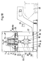
- Chips fall down into a chip conveyor 45, from where they are in a chip carriage 46 (FIG. 18) be transported away. This makes the working space 34 absolutely tight from loading and unloading zone 39 and the measuring zone 35 separately.
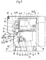
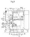
- a probe designated, on a turret unit 48 and tool carrier 50 is arranged with a horizontal axis 49.
- the tool carrier 50 carries several on its circumference Tools, for example chisel 51 and drill 52.
- a drive motor for the turret unit 48 designated.
- the motor spindle 3 is in the direction of the Z axis motor-driven and points at its lower end a chuck 54 for receiving workpieces 42 from the storage conveyor 41.
- the motor spindle 3 dips through one of its outer dimensions adapted bore 56 ( Figure 2) in the sheet metal cover 4 in the work area 34 a.
- the motor spindle is on its outer lateral surface 57 3 sealed by a seal, not shown, so that at this point the work space 34 dirt and moisture-proof sealed to the outside are.
- the motor spindle 3 is in the pick-up spindle automatic lathe particularly suitable, except for the turning operations also the workpiece change in just five, for example Seconds to execute.
- the headstock unit 3, 5 By programming the headstock unit 3, 5, the workpiece parameters for Loading and unloading of workpieces 103, 55 can be used. All movements for loading and unloading the Spindle 3, for machining and for measuring the Workpieces 55 are carried out with the pick-up spindle 3.
- the conveyor belt 41 becomes the 103 to be processed and conveyed the finished workpieces 55.
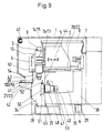
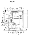
- the processing machine is located in the station shown in FIG. 4, the door 43 already open, that is, in the fully down lowered position. Then the motor spindle 3 moves in the direction of the arrow Z down.
- the chuck 54 grips a workpiece blank 103, which is on the Storage and conveyor belt 41 is located.
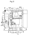
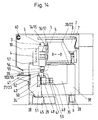
- the workpiece spindle is then shown in FIG Moved up in the direction of arrow Z, the door 44 to measuring zone 35 fully open, so that according to Figure 13 the cross slide 5 with the motor spindle 3 and the workpiece 55 to that on the turret unit 48 mounted probe 47 can move.
- Measurement programs can be in the CNC control of the Machine. So it is possible to be measured immediately after a tool change. It is also possible to continue during production predetermined parts, for example every tenth or twentieth workpiece.
- FIGS. 1 to 17 illustrated processing machine is designed that a simple machine control panel, with those for the Production necessary controls becomes.
- FIGS. 18 to 21 are the same reference numerals for parts with the same function as in the embodiment according to the figures 1 to 17 have been used.
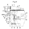
- the embodiment 18 to 20 are in the guide walls trained side walls 26 and 27 of the Machine base body 6 two at a distance and parallel mutually arranged tool carriers for standing Tools 58 and rotating tools 59 a motor-driven turret shaft 60 is arranged.
- the tool carriers 58, 59 carry on their Scope of several tools, of which only the Tools 61 (fixed) and 62 (rotating) with reference numerals have been provided.
- Figures 19 and 20 In training after Figures 19 and 20 is the machine base 6 of a tool storage belt 63 ring-shaped enclosed on which the various tools 64, 70 in preparation with their steep taper 64 after are placed facing up or down.
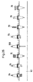
- the tools hang (64) or stand (70) vertically in the Tool storage tape 63 ( Figure 26), which each can supply the required tools in cycles.
- the tool storage tape 63 is driven by a motor and also in the CNC control of the machine included.
- the ring-shaped tool magazine 63 is from a storage and conveyor belt 65 enclosed is also powered and also in the CNC control is included and on which the too machining workpieces 103 of the same or different Type and the finished workpieces 55 cycles by motor drive of the storage and Conveyor belt 65 are moved.
- the finished ones Workpieces 55 are z. B. not by one shown converter transported away.
- the motor spindle 3 takes a workpiece 103 from the storage and conveyor belt 65, being in vertical Direction, i.e. in the direction of the Z axis Hub executes. After picking up the workpiece 103 drives the motor spindle 3 in the direction of the Z axis z. B. 160 mm vertically upwards.
- the working room 34 closing door 43 is by driving vertically down opened so that the motor spindle 3 with the cross slide 5 in the direction of the X axis, that is can execute a stroke horizontally. In the illustrated Embodiment is this stroke, for example 980 mm.
- the motor spindle 3 with the Cross slide 5 then stops in the direction of position 66 with the first clamping, where the desired one Machining, for example drilling a hole by a tool, for example 70 becomes.
- the headstock unit moves in the first clamping 3, 5 to position 68, in which the semi-finished Workpiece 102 passed on to the clamping device 69 becomes.
- the tensioning device 84 can e.g. B. the steep taper a tool 64, 70 record. Will in the Position 68 the workpiece 102 from the jig 69 held, then done by a in the jig 84 recorded tool 64 further processing.
- the tools required are each from the Tool magazine 63 fetched and those not required Tools in the tool magazine 63 through the Motor spindle 3 removed.
- the door 44 becomes Measuring zone 35 opened and the headstock unit 3, 5 the tool moves into the measuring zone 35, where a probe 47 arranged on a displaceable arm 71 is.
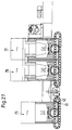
- FIG. 28 Another alternative to chaining multiple Single machines 78, 79, 80, 81, 82 and 83 into one Figure 28 shows the transfer line different machines different, predetermined Processing operations, after their completion the Part passed on to the next processing machine becomes.
- the transport can be done by translators happen fully automatically.
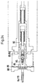
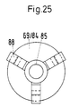
- All clamping devices for workpieces and tools in all embodiments 24 and 25 be configured. Acting combined clamping devices 69, 84 with a central tool holder 85 for the Steep taper 86 suitable tools 64, 70 and jaws 88, which are guided on guides 89. By a pull rod 90 can optionally both the tool holder 85 and the jaws 88 actuated become. The jaws are in use covered as a tool holder.
- the protective caps can in the manner described by the Pick-up spindle, i.e. motor spindle 3, moves and be operated.
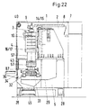
- FIGS. 22 and 23 are the same reference numerals for parts with the same function as in the embodiment according to the figures 1 to 17 have been used.
- the motor spindle 3 equipped with a CNC-controlled facing head 67. This makes further processing operations possible.
- the clock conveyor transports 36 the workpieces 33 through openings in the machine base 6 directly into the processing position. There are they from a z. B. centrically exciting device 32 for subsequent processing by the Facing head 67 clamped with tools 87.
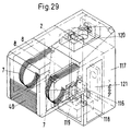
- the one shown in FIG. 29 as an energy container trained container contains suitable electrical equipment 117, a hydraulic aggregate 119, a central cooling 120, a central lubrication 116 with Pump, oil tank and hoses as well as a heat exchanger for the control cabinet 121 and the ready-to-connect cabling and piping, if necessary with plug contacts.
- the container shown in FIG. 29 is a side view approximately L-shaped and has at least a door 118 through which the inside of the L-leg of the container is walkable, for example the units and parts arranged therein waiting. This allows the container to move in space and time independent of the other mechanical units of the machining center installed be so that it as an overall movable unit brought to the rest of the machine and on this can be installed.
- the motor spindle 3 is centered in the cross slide 5 arranged and is in a hydrostatic guide 114, 115 moved in the vertical direction.
- the hydrostatic guide 114, 115 leads to good damping properties and higher Manufacturing quality.
- the loading and unloading zone 39 is behind the work room 34 inside the machining center. This makes the loading and unloading time clear shortened.
- the storage and transport belt 41 is through Recesses 30 (Fig. 2) in the rear area of the Machine base body 6 in the loading and unloading zone 39 passed through the machining center.
- the probe is used to measure the workpieces 55 47 after opening the door 43 in the work area 34 swung in (Fig. 32, 33).
- the measuring zone 35 is no longer separate from the work area as with the arranged above described embodiments, but lies both in the work room 34 and in the Loading and unloading zone 39 (Fig. 32, 33).
- the machining cell is completely one unit transported. Commissioning at the customer can therefore be carried out in a comparatively short time become.
Landscapes
- Mechanical Engineering (AREA)
- Engineering & Computer Science (AREA)
- Turning (AREA)
- Machine Tool Units (AREA)
- Electrical Discharge Machining, Electrochemical Machining, And Combined Machining (AREA)
- Jib Cranes (AREA)
- Auxiliary Devices For Machine Tools (AREA)
- Separation By Low-Temperature Treatments (AREA)
- Fluid-Pressure Circuits (AREA)
- Automatic Tool Replacement In Machine Tools (AREA)
- Crushing And Pulverization Processes (AREA)
- Shovels (AREA)
- Polishing Bodies And Polishing Tools (AREA)
- Drilling And Boring (AREA)
- Finish Polishing, Edge Sharpening, And Grinding By Specific Grinding Devices (AREA)
- Multi-Process Working Machines And Systems (AREA)
- Paper (AREA)
- Disintegrating Or Milling (AREA)
Priority Applications (10)
| Application Number | Priority Date | Filing Date | Title |
|---|---|---|---|
| AU36786/93A AU657852B2 (en) | 1992-04-10 | 1993-04-06 | Machining centre constructed from assemblies |
| BR9301487A BR9301487A (pt) | 1992-04-10 | 1993-04-07 | Central de usinagem composta de grupos em modulos |
| MX9302059A MX9302059A (es) | 1992-04-10 | 1993-04-07 | Centro de mecanizado integrado por diferentes componentes. |
| US08/043,796 US5439431A (en) | 1992-04-10 | 1993-04-07 | Machining centre constructed from assemblies |
| CA002093773A CA2093773C (en) | 1992-04-10 | 1993-04-08 | Machining centre constructed from assemblies |
| JP5083173A JP2653413B2 (ja) | 1992-04-10 | 1993-04-09 | モジュール構造部分から構成された工作機械ユニット |
| KR1019930005922A KR0124546B1 (ko) | 1992-04-10 | 1993-04-09 | 머시닝센터 |
| CZ93627A CZ282078B6 (cs) | 1992-04-10 | 1993-04-09 | Obráběcí centrum složené z konstrukčních-stavebnicových celků |
| CN93104213A CN1059622C (zh) | 1992-04-10 | 1993-04-10 | 部件组合式加工中心 |
| UA93002189A UA32407C2 (uk) | 1992-04-10 | 1993-06-18 | Обробляючий центр |
Applications Claiming Priority (2)
| Application Number | Priority Date | Filing Date | Title |
|---|---|---|---|
| DE4212175 | 1992-04-10 | ||
| DE4212175A DE4212175A1 (de) | 1992-04-10 | 1992-04-10 | Aus Baugruppen zusammengesetztes Bearbeitungszentrum |
Publications (4)
| Publication Number | Publication Date |
|---|---|
| EP0568798A1 EP0568798A1 (de) | 1993-11-10 |
| EP0568798B1 EP0568798B1 (de) | 1998-07-15 |
| EP0568798B2 EP0568798B2 (de) | 2003-10-01 |
| EP0568798B9 true EP0568798B9 (de) | 2004-05-06 |
Family
ID=6456608
Family Applications (1)
| Application Number | Title | Priority Date | Filing Date |
|---|---|---|---|
| EP93104144A Expired - Lifetime EP0568798B9 (de) | 1992-04-10 | 1993-03-14 | Aus Baugruppen zusammengesetztes Bearbeitungszentrum |
Country Status (10)
| Country | Link |
|---|---|
| EP (1) | EP0568798B9 (enExample) |
| KR (1) | KR0124546B1 (enExample) |
| AT (1) | ATE168303T1 (enExample) |
| DE (3) | DE4212175A1 (enExample) |
| DK (1) | DK0568798T4 (enExample) |
| ES (1) | ES2118153T5 (enExample) |
| PL (1) | PL171162B1 (enExample) |
| RU (1) | RU2129064C1 (enExample) |
| UA (1) | UA32407C2 (enExample) |
| ZA (1) | ZA932520B (enExample) |
Cited By (4)
| Publication number | Priority date | Publication date | Assignee | Title |
|---|---|---|---|---|
| DE202008017297U1 (de) | 2008-05-02 | 2009-07-09 | Emag Holding Gmbh | Werkzeugmaschinenschlitten |
| EP2263827A1 (de) | 2009-06-16 | 2010-12-22 | MAG IAS GmbH | Werkzeugmaschine zur Bearbeitung von Werkstücken |
| DE102009025009A1 (de) | 2009-06-16 | 2010-12-23 | Mag Ias Gmbh | Werkzeugmaschine zur Bearbeitung von Werkstücken |
| DE102009054043A1 (de) | 2009-11-20 | 2011-05-26 | Mag Ias Gmbh | Werkzeugmaschine zur Bearbeitung von Werkstücken |
Families Citing this family (47)
| Publication number | Priority date | Publication date | Assignee | Title |
|---|---|---|---|---|
| DE4322918C1 (de) * | 1993-07-09 | 1995-02-02 | Emag Masch Vertriebs Serv Gmbh | Aus Baugruppen zusammengesetztes Bearbeitungszentrum |
| DE4422416C1 (de) * | 1994-06-29 | 1996-01-11 | Magnus Dipl Ing Gruener | Bearbeitungszentrum |
| GB9418420D0 (en) * | 1994-09-13 | 1994-11-02 | Mckeown Neil A | Composition for the treatment of an energy imbalance in ruminents |
| DE19544573C1 (de) * | 1995-11-30 | 1996-09-12 | Helmut Pauser | Verfahren und Vorrichtung zur Fräsbearbeitung dreidimensionaler Werkstücke |
| US6021695A (en) * | 1996-11-11 | 2000-02-08 | Hitachi Seiki Co., Ltd. | Lathe and a machining system of a lathe |
| DE19726309A1 (de) * | 1997-06-20 | 1998-12-24 | Emag Masch Vertriebs Serv Gmbh | Bearbeitungszelle |
| DE19729369C5 (de) * | 1997-07-09 | 2008-08-21 | Teamtechnik Maschinen Und Anlagen Gmbh | Autarker Bearbeitungsplatz und daraus bestehende Bearbeitungsstraße |
| DE19825523A1 (de) * | 1998-06-08 | 1999-12-16 | Ilg Gmbh | Werkzeugmaschine |
| DE19856863C2 (de) * | 1998-12-09 | 2003-07-17 | Alzmetall Werkzeugmasch | Werkzeugmaschine |
| DE19900294B4 (de) * | 1999-01-07 | 2004-01-15 | Ilg Gmbh | Werkzeugmaschine |
| DE19903906A1 (de) * | 1999-02-01 | 2000-08-10 | Boehringer Werkzeugmaschinen | Werkzeugmaschine |
| DE19904860C2 (de) * | 1999-02-05 | 2003-11-13 | Gildemeister Drehmaschinen Gmb | Vertikaldrehmaschine |
| DE10002053C2 (de) * | 2000-01-19 | 2002-03-14 | Emag Maschfab Gmbh | Vorrichtung zur Komplettfertigung komplexer Werkteile |
| RU2220835C2 (ru) * | 2000-07-11 | 2004-01-10 | ООО "Тольяттинский механический завод" | Способ компоновки автоматизированных установок для изготовления и обработки плоских деталей и установка воздушно-плазменной резки для его осуществления |
| DE10203560C5 (de) * | 2002-01-29 | 2008-08-28 | Emag Holding Gmbh | Bearbeitungszentrum |
| DE20211744U1 (de) * | 2002-07-30 | 2002-09-19 | ILG GmbH, 71554 Weissach | Werkzeugmaschine zum Bearbeiten von Futterteilen |
| DE10252710B4 (de) * | 2002-11-11 | 2004-11-04 | J.G. Weisser Söhne | Drehmaschine |
| DE10260253A1 (de) * | 2002-12-20 | 2004-07-01 | Giesecke & Devrient Gmbh | Verfahren und Vorrichtung zur Herstellung von Stichtiefdruckplatten und damit hergestellte Druckplatte |
| EP1440765B1 (en) * | 2003-01-21 | 2006-01-04 | Toyoda Koki Kabushiki Kaisha | Cylindrical grinding machine |
| DE10307977C5 (de) * | 2003-02-24 | 2012-04-05 | Emag Holding Gmbh | Verfahren und Vorrichtung zur Bearbeitung von Ausgleichsgehäusen |
| US7201088B2 (en) | 2003-06-23 | 2007-04-10 | J.G. Weisser Söhne | Lathe |
| DE10358681B4 (de) * | 2003-12-12 | 2014-10-30 | J.G. Weisser Söhne | Werkzeugmaschine zum Bearbeiten von wellenartigen Werkstücken |
| DE102004028172A1 (de) * | 2004-06-09 | 2005-12-29 | Magdeburg Werkzeugmaschinen Ag | Universelles, vertikales Bearbeitungszentrum |
| DE102004042090A1 (de) * | 2004-08-30 | 2006-03-02 | Emag Maschinenfabrik Gmbh | Werkzeugmaschine |
| DE102004054247C5 (de) * | 2004-10-18 | 2013-04-11 | Emag Holding Gmbh | Verfahren und Vorrichtung zur Beschickung einer Werkzeugmaschine |
| DE102005021638B4 (de) * | 2005-05-06 | 2007-03-29 | Satisloh Gmbh | Drehmaschine zur Bearbeitung von optischen Werkstücken |
| DE102005043602B4 (de) | 2005-09-12 | 2018-07-26 | Reishauer Ag | Zahnradbearbeitungsmaschine sowie Verfahren zum Betrieb einer solchen Zahnradbearbeitungsmaschine |
| JP4274167B2 (ja) † | 2005-10-18 | 2009-06-03 | 村田機械株式会社 | ワーク計測器付き工作機械 |
| FR2892960A1 (fr) * | 2006-12-08 | 2007-05-11 | Mori Seiki Seisakusho Kk | Machine-outil |
| CN100542738C (zh) * | 2006-12-25 | 2009-09-23 | 郑国宏 | 连帮注塑鞋专用鞋楦铣钻床 |
| KR100973182B1 (ko) * | 2008-02-29 | 2010-07-30 | 주식회사 스토닉 | 현장 가공물 가공장치 |
| RU2381887C1 (ru) * | 2008-05-13 | 2010-02-20 | Государственное образовательное учреждение высшего профессионального образования Курский государственный технический университет | Устройство для обработки деталей на оборудовании с чпу при шлифовании |
| DE102008052540C5 (de) * | 2008-10-21 | 2014-04-17 | Emag Holding Gmbh | Drehmaschine |
| DE102010023277A1 (de) * | 2010-06-10 | 2011-12-15 | Maschinenfabrik Berthold Hermle Ag | Vertikales Bearbeitungszentrum in Gantry- oder Fahrständer-Bauform mit einer Bodenöffnung für die Abfuhr der Bearbeitungsrückstände aus dem Arbeitsraum des Bearbeitungszentrums |
| EP2431124B1 (de) | 2010-09-20 | 2012-10-17 | Gildemeister Drehmaschinen GmbH | Vertikaldrehmaschine |
| DE102011085561A1 (de) * | 2011-06-06 | 2012-12-06 | Robert Bosch Gmbh | Handwerkzeugmaschinenspannvorrichtung |
| DE202011051910U1 (de) | 2011-11-09 | 2013-02-18 | Miyachi Europe GmbH | Bearbeitungseinrichtung |
| DE102011118416B4 (de) * | 2011-11-12 | 2013-05-29 | Emag Holding Gmbh | Werkzeugmaschine mit Werkstückmessvorrichtung |
| DE102012018239A1 (de) * | 2012-09-17 | 2014-03-20 | Emag Holding Gmbh | Werkzeugmaschine |
| RU2523656C1 (ru) * | 2012-12-25 | 2014-07-20 | Олег Савельевич Кочетов | Фрезерно-расточной станок |
| CH710648A1 (de) * | 2015-01-23 | 2016-07-29 | Erowa Ag | Messmaschine zum Vermessen von Werkstücken. |
| DE102015208222B3 (de) * | 2015-05-04 | 2016-09-01 | Wafios Aktiengesellschaft | Drahtverarbeitungsmaschine mit Schutzvorrichtung |
| CN109661291A (zh) * | 2016-09-09 | 2019-04-19 | 株式会社牧野铣床制作所 | 机床 |
| DE102016121200A1 (de) | 2016-11-07 | 2018-05-09 | Mikron Gmbh Rottweil | Bearbeitungszentrum zum Bearbeiten von Werkstücken |
| CN110370087B (zh) * | 2019-07-29 | 2024-01-05 | 宁波运生工贸有限公司 | 一种发动机油管加工设备 |
| GB2592949B (en) * | 2020-03-11 | 2024-11-20 | Effective Cnc Solutions Ltd | Multi-purpose apparatus |
| CN117532355B (zh) * | 2024-01-08 | 2024-07-23 | 江苏鲸工智能装备制造有限公司 | 一种用于机械零件加工的组合机床 |
Family Cites Families (8)
| Publication number | Priority date | Publication date | Assignee | Title |
|---|---|---|---|---|
| IT973680B (it) * | 1971-12-04 | 1974-06-10 | Weisser J Sohne Werkzeugmas Ch | Serie di parti staccate prefabbri cate per la composizione di torni |
| FR2362703A1 (fr) * | 1976-08-30 | 1978-03-24 | Komatsu Mfg Co Ltd | Machine-outil complexe destinee a des usinages multiples |
| DE3274074D1 (en) † | 1982-01-08 | 1986-12-11 | Fanuc Ltd | A spindle head unit |
| EP0215208B1 (en) † | 1982-03-10 | 1991-04-24 | Renishaw plc | Machine tool |
| FR2560541B1 (fr) † | 1984-03-02 | 1987-06-26 | Sateco Sarl | Machine executant diverses operations d'usinage, telles que tournage, fraisage, alesage |
| DE3416660A1 (de) * | 1984-05-05 | 1985-11-07 | J.G. Weisser Söhne Werkzeugmaschinenfabrik GmbH & Co. KG, 7742 St Georgen | Drehmaschine |
| US5025690A (en) * | 1986-11-06 | 1991-06-25 | The Warner & Swasey Company | Vertical spindle turret lathe |
| DE3824602A1 (de) * | 1988-07-19 | 1990-01-25 | Rheinische Maschinenfabrik & E | Maschine zur spanabhebenden bearbeitung von kubischen und rotationssymmetrischen werkstuecken |
-
1992
- 1992-04-10 DE DE4212175A patent/DE4212175A1/de active Granted
-
1993
- 1993-03-14 DE DE59308762T patent/DE59308762D1/de not_active Ceased
- 1993-03-14 ES ES93104144T patent/ES2118153T5/es not_active Expired - Lifetime
- 1993-03-14 DK DK93104144T patent/DK0568798T4/da active
- 1993-03-14 AT AT93104144T patent/ATE168303T1/de active
- 1993-03-14 DE DE9321647U patent/DE9321647U1/de not_active Expired - Lifetime
- 1993-03-14 EP EP93104144A patent/EP0568798B9/de not_active Expired - Lifetime
- 1993-04-08 ZA ZA932520A patent/ZA932520B/xx unknown
- 1993-04-08 PL PL93298447A patent/PL171162B1/pl unknown
- 1993-04-09 RU RU93004677A patent/RU2129064C1/ru active
- 1993-04-09 KR KR1019930005922A patent/KR0124546B1/ko not_active Expired - Lifetime
- 1993-06-18 UA UA93002189A patent/UA32407C2/uk unknown
Cited By (4)
| Publication number | Priority date | Publication date | Assignee | Title |
|---|---|---|---|---|
| DE202008017297U1 (de) | 2008-05-02 | 2009-07-09 | Emag Holding Gmbh | Werkzeugmaschinenschlitten |
| EP2263827A1 (de) | 2009-06-16 | 2010-12-22 | MAG IAS GmbH | Werkzeugmaschine zur Bearbeitung von Werkstücken |
| DE102009025009A1 (de) | 2009-06-16 | 2010-12-23 | Mag Ias Gmbh | Werkzeugmaschine zur Bearbeitung von Werkstücken |
| DE102009054043A1 (de) | 2009-11-20 | 2011-05-26 | Mag Ias Gmbh | Werkzeugmaschine zur Bearbeitung von Werkstücken |
Also Published As
| Publication number | Publication date |
|---|---|
| RU2129064C1 (ru) | 1999-04-20 |
| UA32407C2 (uk) | 2000-12-15 |
| ES2118153T3 (es) | 1998-09-16 |
| PL298447A1 (en) | 1994-08-08 |
| ATE168303T1 (de) | 1998-08-15 |
| DE4212175A1 (de) | 1993-10-14 |
| DK0568798T3 (da) | 1999-02-01 |
| ES2118153T5 (es) | 2004-07-01 |
| KR0124546B1 (ko) | 1997-12-09 |
| DE4212175C2 (enExample) | 1994-02-10 |
| EP0568798A1 (de) | 1993-11-10 |
| PL171162B1 (pl) | 1997-03-28 |
| ZA932520B (en) | 1993-10-28 |
| DK0568798T4 (da) | 2003-10-27 |
| EP0568798B2 (de) | 2003-10-01 |
| DE9321647U1 (de) | 2002-01-03 |
| DE59308762D1 (de) | 1998-08-20 |
| EP0568798B1 (de) | 1998-07-15 |
| KR930021296A (ko) | 1993-11-22 |
Similar Documents
| Publication | Publication Date | Title |
|---|---|---|
| EP0568798B2 (de) | Aus Baugruppen zusammengesetztes Bearbeitungszentrum | |
| CA2093773C (en) | Machining centre constructed from assemblies | |
| DE19749872B4 (de) | Vertikal-Drehmaschine und Bearbeitungssystem mit zwei Maschinenbereichen | |
| EP0737544B1 (de) | Werkzeugmaschine mit mehreren Spindeln | |
| EP0611630B1 (de) | Numerisch gesteuerte Schleifmaschine zum Schleifen von vorzugsweise metallischen Werkstücken, insbesondere Werkzeugen | |
| DE102016205537B4 (de) | Honmaschine mit mehreren Arbeitsstationen und Fertigungsanlage damit | |
| EP3535092B1 (de) | Honmaschine mit mehreren arbeitsstationen | |
| DE3427245A1 (de) | Werkzeugmaschine | |
| DE10119175A1 (de) | Vorrichtung zur Bearbeitung von Werkstücken sowie Verfahren zur Bearbeitung von Werkstücken unter Verwendung einer solchen Vorrichtung | |
| DE102017012075A1 (de) | Bearbeitungsstation | |
| DE102009025009A1 (de) | Werkzeugmaschine zur Bearbeitung von Werkstücken | |
| EP1718435B1 (de) | Bearbeitungsmaschine zum bearbeiten von werkst cken | |
| DE102009054043A1 (de) | Werkzeugmaschine zur Bearbeitung von Werkstücken | |
| EP1807242A1 (de) | Hochflexible werkzeugmaschine mit mehreren werkstückträgern | |
| DE19803563C1 (de) | Werkzeugmaschine, insbesondere Drehmaschine mit wenigstens einer hängend angeordneten horizontalen Arbeitsspindel | |
| EP2762253B1 (de) | Werkzeugmaschine zur Bearbeitung von Werkstücken | |
| EP3624988B1 (de) | Werkzeugmaschine | |
| DE10144679A1 (de) | Bearbeitungszentrum | |
| DE19652460C1 (de) | Werkzeugmaschine mit mehreren Spindeln | |
| DE3530982A1 (de) | Zweispindlige, numerisch gesteuerte drehmaschine | |
| DE4322918C1 (de) | Aus Baugruppen zusammengesetztes Bearbeitungszentrum | |
| DE4330858C1 (de) | Verfahren zum Bearbeiten eines Werkstückes auf einem CNC-Drehautomaten sowie CNC-Drehautomat | |
| DE4441106A1 (de) | Drehmaschine mit zwei parallelen, horizontalen Arbeitsspindeln | |
| DE10354706C5 (de) | Werkzeugmaschine mit Transportvorrichtung | |
| EP4706883A1 (de) | Bearbeitungszentrum zur mechanischen bearbeitung von werkstücken |
Legal Events
| Date | Code | Title | Description |
|---|---|---|---|
| PUAI | Public reference made under article 153(3) epc to a published international application that has entered the european phase |
Free format text: ORIGINAL CODE: 0009012 |
|
| 17P | Request for examination filed |
Effective date: 19930326 |
|
| AK | Designated contracting states |
Kind code of ref document: A1 Designated state(s): AT BE CH DE DK ES FR GB GR IE IT LI LU MC NL PT SE |
|
| 17Q | First examination report despatched |
Effective date: 19950309 |
|
| APAB | Appeal dossier modified |
Free format text: ORIGINAL CODE: EPIDOS NOAPE |
|
| APAD | Appeal reference recorded |
Free format text: ORIGINAL CODE: EPIDOS REFNE |
|
| APAB | Appeal dossier modified |
Free format text: ORIGINAL CODE: EPIDOS NOAPE |
|
| GRAG | Despatch of communication of intention to grant |
Free format text: ORIGINAL CODE: EPIDOS AGRA |
|
| GRAG | Despatch of communication of intention to grant |
Free format text: ORIGINAL CODE: EPIDOS AGRA |
|
| GRAH | Despatch of communication of intention to grant a patent |
Free format text: ORIGINAL CODE: EPIDOS IGRA |
|
| GRAH | Despatch of communication of intention to grant a patent |
Free format text: ORIGINAL CODE: EPIDOS IGRA |
|
| ITF | It: translation for a ep patent filed | ||
| GRAA | (expected) grant |
Free format text: ORIGINAL CODE: 0009210 |
|
| 111Z | Information provided on other rights and legal means of execution |
Free format text: AT BE CH DE DK ES FR GB GR IE IT LI LU MC NL PT SE |
|
| AK | Designated contracting states |
Kind code of ref document: B1 Designated state(s): AT BE CH DE DK ES FR GB GR IE IT LI LU MC NL PT SE |
|
| REF | Corresponds to: |
Ref document number: 168303 Country of ref document: AT Date of ref document: 19980815 Kind code of ref document: T |
|
| REG | Reference to a national code |
Ref country code: CH Ref legal event code: NV Representative=s name: ISLER & PEDRAZZINI AG Ref country code: CH Ref legal event code: EP |
|
| ET | Fr: translation filed | ||
| REF | Corresponds to: |
Ref document number: 59308762 Country of ref document: DE Date of ref document: 19980820 |
|
| REG | Reference to a national code |
Ref country code: ES Ref legal event code: FG2A Ref document number: 2118153 Country of ref document: ES Kind code of ref document: T3 |
|
| GBT | Gb: translation of ep patent filed (gb section 77(6)(a)/1977) |
Effective date: 19980911 |
|
| REG | Reference to a national code |
Ref country code: IE Ref legal event code: FG4D Free format text: GERMAN |
|
| REG | Reference to a national code |
Ref country code: PT Ref legal event code: SC4A Free format text: AVAILABILITY OF NATIONAL TRANSLATION Effective date: 19980720 |
|
| REG | Reference to a national code |
Ref country code: DK Ref legal event code: T3 |
|
| PG25 | Lapsed in a contracting state [announced via postgrant information from national office to epo] |
Ref country code: LU Free format text: LAPSE BECAUSE OF NON-PAYMENT OF DUE FEES Effective date: 19990314 |
|
| PLBQ | Unpublished change to opponent data |
Free format text: ORIGINAL CODE: EPIDOS OPPO |
|
| PLBI | Opposition filed |
Free format text: ORIGINAL CODE: 0009260 |
|
| PLBF | Reply of patent proprietor to notice(s) of opposition |
Free format text: ORIGINAL CODE: EPIDOS OBSO |
|
| 26 | Opposition filed |
Opponent name: INDEX-WERKE KG HAHN & TESSKY Effective date: 19990415 |
|
| PLBF | Reply of patent proprietor to notice(s) of opposition |
Free format text: ORIGINAL CODE: EPIDOS OBSO |
|
| PG25 | Lapsed in a contracting state [announced via postgrant information from national office to epo] |
Ref country code: MC Free format text: LAPSE BECAUSE OF NON-PAYMENT OF DUE FEES Effective date: 19990930 |
|
| RAP2 | Party data changed (patent owner data changed or rights of a patent transferred) |
Owner name: EMAG MASCHINENFABRIK GMBH |
|
| REG | Reference to a national code |
Ref country code: CH Ref legal event code: PFA Free format text: EMAG-MASCHINEN VERTRIEBS- UND SERVICE GMBH TRANSFER- EMAG MASCHINENFABRIK GMBH |
|
| NLT2 | Nl: modifications (of names), taken from the european patent patent bulletin |
Owner name: EMAG MASCHINENFABRIK GMBH |
|
| RDAH | Patent revoked |
Free format text: ORIGINAL CODE: EPIDOS REVO |
|
| APAC | Appeal dossier modified |
Free format text: ORIGINAL CODE: EPIDOS NOAPO |
|
| APAE | Appeal reference modified |
Free format text: ORIGINAL CODE: EPIDOS REFNO |
|
| APAC | Appeal dossier modified |
Free format text: ORIGINAL CODE: EPIDOS NOAPO |
|
| NLS | Nl: assignments of ep-patents |
Owner name: EMAG MASCHINENFABRIK GMBH |
|
| REG | Reference to a national code |
Ref country code: GB Ref legal event code: IF02 |
|
| APAC | Appeal dossier modified |
Free format text: ORIGINAL CODE: EPIDOS NOAPO |
|
| PLAW | Interlocutory decision in opposition |
Free format text: ORIGINAL CODE: EPIDOS IDOP |
|
| PUAH | Patent maintained in amended form |
Free format text: ORIGINAL CODE: 0009272 |
|
| 27A | Patent maintained in amended form |
Effective date: 20031001 |
|
| AK | Designated contracting states |
Kind code of ref document: B2 Designated state(s): AT BE CH DE DK ES FR GB GR IE IT LI LU MC NL PT SE |
|
| REG | Reference to a national code |
Ref country code: CH Ref legal event code: AEN Free format text: AUFRECHTERHALTUNG DES PATENTES IN GEAENDERTER FORM |
|
| REG | Reference to a national code |
Ref country code: SE Ref legal event code: RPEO |
|
| REG | Reference to a national code |
Ref country code: GR Ref legal event code: EP Ref document number: 20030403930 Country of ref document: GR |
|
| NLR2 | Nl: decision of opposition |
Effective date: 20031001 |
|
| NLR3 | Nl: receipt of modified translations in the netherlands language after an opposition procedure | ||
| GBTA | Gb: translation of amended ep patent filed (gb section 77(6)(b)/1977) |
Effective date: 20040107 |
|
| REG | Reference to a national code |
Ref country code: PT Ref legal event code: PD4A Free format text: EMAG MASCHINENFABRIK GMBH DE Effective date: 20031212 |
|
| REG | Reference to a national code |
Ref country code: ES Ref legal event code: DC2A Date of ref document: 20031229 Kind code of ref document: T5 |
|
| ET3 | Fr: translation filed ** decision concerning opposition | ||
| ET2 | Fr: translation filed ** revision of the translation of the modified patent after opposition | ||
| ET3 | Fr: translation filed ** decision concerning opposition | ||
| APAH | Appeal reference modified |
Free format text: ORIGINAL CODE: EPIDOSCREFNO |
|
| REG | Reference to a national code |
Ref country code: CH Ref legal event code: PFA Owner name: EMAG HOLDING GMBH Free format text: EMAG MASCHINENFABRIK GMBH#AUSTRASSE 24#D-73084 SALACH (DE) -TRANSFER TO- EMAG HOLDING GMBH#AUSTRASSE 24#73084 SALACH (DE) |
|
| NLT1 | Nl: modifications of names registered in virtue of documents presented to the patent office pursuant to art. 16 a, paragraph 1 |
Owner name: EMAG HOLDING GMBH |
|
| REG | Reference to a national code |
Ref country code: FR Ref legal event code: CD |
|
| REG | Reference to a national code |
Ref country code: PT Ref legal event code: PD4A Owner name: EMAG HOLDING GMBH, DE Effective date: 20060606 |
|
| REG | Reference to a national code |
Ref country code: ES Ref legal event code: PC2A |
|
| REG | Reference to a national code |
Ref country code: CH Ref legal event code: PCAR Free format text: ISLER & PEDRAZZINI AG;POSTFACH 1772;8027 ZUERICH (CH) |
|
| PGFP | Annual fee paid to national office [announced via postgrant information from national office to epo] |
Ref country code: DE Payment date: 20090330 Year of fee payment: 17 |
|
| PG25 | Lapsed in a contracting state [announced via postgrant information from national office to epo] |
Ref country code: DE Free format text: THE PATENT HAS BEEN ANNULLED BY A DECISION OF A NATIONAL AUTHORITY Effective date: 20091013 |
|
| PGFP | Annual fee paid to national office [announced via postgrant information from national office to epo] |
Ref country code: IE Payment date: 20120317 Year of fee payment: 20 Ref country code: FR Payment date: 20120405 Year of fee payment: 20 |
|
| PGFP | Annual fee paid to national office [announced via postgrant information from national office to epo] |
Ref country code: PT Payment date: 20120301 Year of fee payment: 20 |
|
| PGFP | Annual fee paid to national office [announced via postgrant information from national office to epo] |
Ref country code: GR Payment date: 20120327 Year of fee payment: 20 Ref country code: SE Payment date: 20120321 Year of fee payment: 20 Ref country code: GB Payment date: 20120327 Year of fee payment: 20 Ref country code: IT Payment date: 20120326 Year of fee payment: 20 Ref country code: DK Payment date: 20120322 Year of fee payment: 20 |
|
| PGFP | Annual fee paid to national office [announced via postgrant information from national office to epo] |
Ref country code: NL Payment date: 20120403 Year of fee payment: 20 Ref country code: BE Payment date: 20120402 Year of fee payment: 20 Ref country code: CH Payment date: 20120425 Year of fee payment: 20 |
|
| REG | Reference to a national code |
Ref country code: DK Ref legal event code: EUP |
|
| REG | Reference to a national code |
Ref country code: NL Ref legal event code: V4 Effective date: 20130314 |
|
| REG | Reference to a national code |
Ref country code: PT Ref legal event code: MM4A Free format text: MAXIMUM VALIDITY LIMIT REACHED Effective date: 20130314 |
|
| REG | Reference to a national code |
Ref country code: CH Ref legal event code: PL |
|
| PGFP | Annual fee paid to national office [announced via postgrant information from national office to epo] |
Ref country code: AT Payment date: 20120330 Year of fee payment: 20 |
|
| BE20 | Be: patent expired |
Owner name: *EMAG HOLDING G.M.B.H. Effective date: 20130314 |
|
| REG | Reference to a national code |
Ref country code: GB Ref legal event code: PE20 Expiry date: 20130313 |
|
| PG25 | Lapsed in a contracting state [announced via postgrant information from national office to epo] |
Ref country code: GB Free format text: LAPSE BECAUSE OF EXPIRATION OF PROTECTION Effective date: 20130313 |
|
| REG | Reference to a national code |
Ref country code: SE Ref legal event code: EUG |
|
| REG | Reference to a national code |
Ref country code: AT Ref legal event code: MK07 Ref document number: 168303 Country of ref document: AT Kind code of ref document: T Effective date: 20130314 |
|
| REG | Reference to a national code |
Ref country code: GR Ref legal event code: MA Ref document number: 20030403930 Country of ref document: GR Effective date: 20130315 |
|
| PG25 | Lapsed in a contracting state [announced via postgrant information from national office to epo] |
Ref country code: PT Free format text: LAPSE BECAUSE OF EXPIRATION OF PROTECTION Effective date: 20130321 |
|
| PGFP | Annual fee paid to national office [announced via postgrant information from national office to epo] |
Ref country code: ES Payment date: 20120321 Year of fee payment: 20 |
|
| REG | Reference to a national code |
Ref country code: ES Ref legal event code: FD2A Effective date: 20130719 |
|
| PG25 | Lapsed in a contracting state [announced via postgrant information from national office to epo] |
Ref country code: ES Free format text: LAPSE BECAUSE OF EXPIRATION OF PROTECTION Effective date: 20130315 |
|
| PG25 | Lapsed in a contracting state [announced via postgrant information from national office to epo] |
Ref country code: IE Free format text: LAPSE BECAUSE OF EXPIRATION OF PROTECTION Effective date: 20130314 |