EP0568787B1 - Be- und Entladeeinrichtung für Etagenbacköfen - Google Patents
Be- und Entladeeinrichtung für Etagenbacköfen Download PDFInfo
- Publication number
- EP0568787B1 EP0568787B1 EP93103542A EP93103542A EP0568787B1 EP 0568787 B1 EP0568787 B1 EP 0568787B1 EP 93103542 A EP93103542 A EP 93103542A EP 93103542 A EP93103542 A EP 93103542A EP 0568787 B1 EP0568787 B1 EP 0568787B1
- Authority
- EP
- European Patent Office
- Prior art keywords
- loading
- lifting
- equipment according
- unloading equipment
- unloading
- Prior art date
- Legal status (The legal status is an assumption and is not a legal conclusion. Google has not performed a legal analysis and makes no representation as to the accuracy of the status listed.)
- Expired - Lifetime
Links
Images


Classifications
-
- A—HUMAN NECESSITIES
- A21—BAKING; EDIBLE DOUGHS
- A21B—BAKERS' OVENS; MACHINES OR EQUIPMENT FOR BAKING
- A21B3/00—Parts or accessories of ovens
- A21B3/07—Charging or discharging ovens
Definitions
- the invention relates to a loading and unloading device for deck ovens according to the preamble of claim 1.
- Feeding aids known to be stationary in front of or on Oven are mounted. This also includes crawling tapes for crawling the finished baked goods out of the stoves of the deck oven used. Furthermore, it is announced that these loading aids in front of the furnace front onto the floor using a trolley (DE 29 34 369 A1) or are designed to be movable on rails (FR 1 584 271).
- the arrangement of the work table on a pair of lifting shears represents an extremely unstable construction with which those arising from the movement in three levels mastered different moments in any way can be, so that with this no exact Positioning the work table on the individual Loading and unloading points can be realized.
- a Herplatten planer with a suction nozzle is known.
- This hob grinder dimensioned for hand use, has one Iron block with suction nozzles and scraper plates attached to them residues solidified on the hob should be removed by scraping.
- the suction nozzles are connected to a holding tube via a suction nozzle, which is connected to a suction device.
- the hob is moved back and forth until the whole Stove area is cleaned. So the entire stove surface can be covered by one the only insertion of the hob is not cleaned.
- the Manual operation has the disadvantage in large deck ovens that it is very is energy-consuming and time-consuming and, in many cases, additionally the use requires a ladder.
- the invention is based on the object Loading and unloading device for Provide deck ovens that cover the hearth floors of the deck ovens keeps cleaner.
- the loading and unloading device according to the invention is fully automatic depending on the respective baking program in three axes, in the X-axis in front of the oven front, in the Y-axis over the different cooker heights and in the Z-axis into and out of the oven and proofing cabinet movable.
- the loading table is safely guided by the torsion-resistant lifting columns and can be precisely fed to any stop position via the control device.
- the provided suction device which when entering and exiting the oven and proofer is subjected to a suction air flow the baking surfaces, the belt and the proofer are kept clean.
- Claim 2 In a development of the invention according to the features of Claim 2 is one for the lifting and lowering movement secure guidance and precise drive ensured.
- a particularly favorable development of the invention is by the features of claim 5 for the movement of the Trolley shown in front of the oven front.
- a particularly useful embodiment of the The loading table is based on the characteristics of the Claim 10 given.
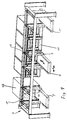
- a self-supporting track 1 is freely set up in front of a furnace front consisting of four multi-level baking ovens 11 and a proofing cabinet 12 arranged next to it.
- a trolley 4 which can be moved freely in the X-axis.
- An elongated loading table 2 can be lifted and lowered (Y-axis) on the trolley 4 by means of two lifting columns 3.
- the loading table 2 is provided with a tongue 23 (Z axis) which can be moved back and forth via a motor 15 and over which a belt 22 (crawling belt) which can be driven forwards and backwards is guided.
- the work table is shown in three positions: on the left in front of the proofing cabinet 12 (2 '), in the middle in front of a deck oven 11 (2) and on the right in the delivery position (2'').
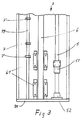
- the lifting columns 3 consist of torsion-resistant, canted U-profile supports with a lower profile-closing base plate 31 (FIG. 3).
- a vertical threaded spindle 5 and guide rod 6 are accommodated in each lifting column 3.
- the threaded spindle 5 is arranged on a ball bearing mounted on the base plate 31 (the above bearing in the lifting column is not shown) and is provided with a spindle nut 51.
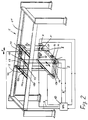
- the threaded spindles 5 are connected via drive axles 53 to a motor 14 carried by the trolley 4 (FIG. 2).
- Each guide rod 6 is assigned two guide carriages 61.
- the loading table is screwed with its side parts 21 via flange plates 8 to the spindle nut 51 and the guide slide 61.
- the loading and unloading device is equipped with four frequency-controlled motors (13, 14, 15 and 17) which are controlled by a control device 10.
- the control device 10 is designed as a programmable logic controller and is referred to below as a PLC.
- the basic structure of this PLC 10 is shown in FIG. 2.
- the driving direction or the direction of rotation and the speed of the motors are specified in each case via the PLC 10.
- All stop positions are recorded in each axis via inductive proximity switches.
- the activation of the respective proximity switch corresponding to the desired stop position is set by the PLC, that is to say the PLC addresses the respective stop position depending on the furnace program and activates the proximity switch 7 there.
- the movement in the Z direction takes place through the tongue 23, those in the rare parts 21 of the loading table 2 out and over the motor 15 - in the oven 11 or Proofing cabinet 12 can be moved in and out.
- the band 22 receiving the dough pieces 18 is over the radiused tongue tip 23 'guided and at the back with its two ends on the pair of drums 16.17 attached.
- the pair of drums 16, 17, consisting of a drum motor 17 and the belt drum 16, corresponds to each other via the toothing 16 ', 17'.
- the two side parts 21 are on a support plate 24 and connected to each other by a tubular frame 25, this Longitudinal spars and has a square profile.
- the 3rd switch uses the brake stop signal in all stop positions. In this way, each position is approached in the X direction.
- the PLC acts on the motor 13, which is connected via a continuous shaft 131 to a bevel gear 133 via axle shafts 132 with the rollers 41 of the trolley 4.
- the stop position in the lifting-lowering operation corresponds to the floors of the oven 11 of the loading and unloading flap of the proofing cabinet 12 and any delivery positions that may still be present.
- Each stop position in the Y direction is fixed by a pair of proximity switches 7, 7 '.
- the speed on the braking ramp is reduced when the first switch of the respective pair is reached.
- the brake is applied and the drive stops immediately. In this way, exact positions can be reached via overdrive / creep speed even in the stroke-lowering mode.
- the respectively active pair of limit switches (in the drawing 7,7 ') is addressed via the PLC from the program.
- the PLC acts on the motor 14 which is fixedly coupled to the threaded spindles 5 of the lifting columns 3 by means of two axes 53.
- Movement in the Z direction (retraction and extension of the tongue 23)
- the movement in the Z direction ie the insertion of the tongue 23 into the oven 11 or proofing cabinet 12 and the removal of the tongue 23, is divided into two movement sections, which, however, take place simultaneously.
- the tongue 23 moves into the proofer 12, dough pieces 18 are to be picked up.
- the band 22 is simultaneously pulled backwards over the tongue 23.
- the drum motor 17 turns to the left and unwinds the band 22 to the front, the revolving band drum 16 rotates in the opposite direction and winds the band 22 to the rear.
- Direction of rotation and speed are controlled synchronously with the tongue 23 via the PLC and frequency converter.
- the movement of the tongue 23 is carried out by the motor 15 and the movement of the belt 22 by the pair of drums 16, 17.
- the pair of limit switches 73 reports the direction of movement of the belt drum 16. The direction of movement of the drums is recognized by the pulse train at both proximity switches 73.
- the path of the belt 22 is determined via a pulse counter 76.
- Lifting mechanism / structure of the lifting column The loading table 2 of the loading and unloading device is guided up and down in two lifting columns 3.
- the lifting movement is realized via a threaded spindle 5, which is installed in the column 3.
- the threaded spindles 5 are each driven by a worm gear.
- the worm gears of both columns are connected to shafts 53 with a motor 14.
- the motor 14 drives both worm gears synchronously.
- the motor 14 is located on the trolley 4 (Fig. 2).
- the threaded spindle 5 rotates, the spindle nut 51 moves up and down on the spindle 5.
- the flange plate 8 is screwed to the spindle nut 51 and the loading table is fastened to the flange plate 8.
- the loading table 2 is also connected to the two movement slides 61 via the flange plate 8.
- the movement slides 61 move up and down on the guide rod 6.
- the pair of limit switches, which fixes the braking and stop position in the Y axis, is designated with 7.7 '.
- Motors 13, 14, 15, 16 and 17 are connected to PLC 10 via lines 9 electrically connected.
- the integrated suction device is shown in FIG.
- the band 22 is deflected over a radius at the tip 23 ′, the tongue 23 and is returned directly below the support plate 24.
- the two side guides 21 are connected to a tubular frame 25, this tubular frame 25 also serves for air guidance as a suction pipe.
- this tubular frame 25 also serves for air guidance as a suction pipe.
- four square suction tubes are guided forward under the support plate 24 and open into the tube 19 below the belt 22.
- This suction pipe system on the tube 19 below the belt 22 draws air and burns it Flour, crumbs and baking residues sucked off.
- the dust is drawn off via the suction pipe system in the loading table 2 via a hose system onto the trolley 4 and down from the trolley 4 into a filter system. In this way it is possible for the first time to dispense with manual cleaning of the oven's baking plates, since the device automatically keeps the baking surface clean. Flour residues from the topping belt are also effectively sucked off by this suction pipe system.
Landscapes
- Life Sciences & Earth Sciences (AREA)
- Engineering & Computer Science (AREA)
- Food Science & Technology (AREA)
- Baking, Grill, Roasting (AREA)
- Warehouses Or Storage Devices (AREA)
- Meat, Egg Or Seafood Products (AREA)
- Drying Of Solid Materials (AREA)
- Furnace Charging Or Discharging (AREA)
- Saccharide Compounds (AREA)
- Peptides Or Proteins (AREA)
- Medicines That Contain Protein Lipid Enzymes And Other Medicines (AREA)
Description
Die erfindungsgemässe Be-und Entladeeinrichtung ist in Abhängigkeit des jeweiligen Backprogrmmes in drei Achsen, in der X-Achse vor der Ofenfront, in der Y-Achse über die verschiedenen Herdhöhen und in der Z-Achse in den Ofen und Gärschrank hinein und wieder heraus vollautomtisch verfahrbar. Durch die verwindungsfesten Hubsäulen ist der Beschickungstisch sicher geführt und über die Steuereinrichtung jeder Halteposition exakt zuführbar.
- Fig. 1
- eine Gesamtansicht einer vor einer Ofenfront angeordneten Be-und Entladeeinrichtung
- Fig. 2
- eine vergrösserte Darstellung gemäss Fig. 1 ohne Ofenfront und mit prinzipiellen Aufbau einer SPS-Steuerung
- Fig. 3
- den unteren inneren Teil einer Hubsäule 3 mit Führungsstange 6, Gewindespindel 5, Steuerschalter 7, 7' ohne Flanschplatte 8
- Fig. 4
- eine Teilansicht des Beschickungstisches 2 zwischen zwei Herdplatten 11' im Schnitt dargestellt.
- Fig. 5
- den Antrieb für das Band 22 ohne Beschickungstisch 2
In der Gesamtdarstellung gemäss Fig. 1 ist der Arbeitstisch in drei Positionen:links vor dem Gärschrank 12 (2'), in der Mitte vor einem Etagenbackofen 11 (2) und rechts in der Abgabeposition (2'') dargestellt.
In jeder Hubsäule 3 ist eine vertikale Gewindespindel 5 und Führungsstange 6 untergebracht.
Die Gewindespindel 5 ist über ein auf der Bodenplatte 31 befestigtes Lager 52 kugelgelagert angeordnet (die obrige Lagerung in der Hubsäule ist nicht dargestellt) und mit einer Spindelmutter 51 versehen. Oben sind die Gewindespindeln 5 über Antriebsachsen 53 mit einem von der Laufkatze 4 getragenen Motor 14 verbunden (Fig.2). Jeder Führungsstange 6 sind zwei Führungsschlitten 61 zugeordnet.
Der Beschickungstisch ist mit seinen Seitenteilen 21 über Flanschplatten 8 mit der Spindelmutter 51 und den Führungsschlitten 61 verschraubt. In einer der beiden Hubsäulen 3 ist ferner eine mit entsprechend den Herdabständen des Etagenbackofens 11 mit Steuerschalterpaaren 7,7' ausgerüstete Leiste 79 zur Steuerung der Hubbewegung des Arbeitstisches 2 angeordnet.
Die Be-und Entladeeinrichtung ist mit vier frequenzgeregelten Motoren (13,14,15 und 17) ausgerüstet, die über eine Steuereinrichtung 10 gesteuert werden. Die Steuereinrichtung 10 ist als speicherprogrammierbare Steuerung ausgebildet und wird im folgenden als SPS bezeichnet. Der prinzipielle Aufbau dieser SPS 10 ist in der Fig. 2 dargestellt.
Über die SPS 10 werden jeweils die Fahrtrichtung bzw. die Drehrichtung und die Geschwindigkeit der Motoren vorgegeben. Alle Haltepositionen werden in jeder Achse über induktive Näherungsschalter erfasst. Die Aktivierung des jeweiligen Näherungsschalters entsprechend der gewünschten Halteposition wird von der SPS gesetzt, das heisst die SPS adressiert die jeweilige Halteposition in Abhängigkeit des Ofenprogrammes und aktiviert den dortigen Näherungsschalter 7.
Das Gerät bewegt sich in der X-Achse vor einem Gärschrank 12 und maximal fünf Etagenbacköfen 11. Jeder Ofen und auch der Gärschrank sind durch Kontaktgeber identifiziert (in der Zeichnung nicht näher dargestellt). An der Laufkatze 4 sind 3 oder mehr Näherungsschalter 74 montiert die mitbewegt werden. Jede Halteposition in X-Richtung ist über eine bestimmte Anordnung von Geberschienen identifiziert. Die 3 Näherungsschalter 74 (z.B. 1 Schalter bedeckt und 2 Schalter bedeckt= Ofenposition 1) können bis zu 4 verschiedene Haltepositionen identifizieren. Die Fahrtrichtung wird über die Impulsfolge festgestellt. Für weitere Haltepositionen sind weitere Näherungsschalter 74 zu installieren. Die 1. und 2. Näherungsschalter 74 identifizieren gleichzeitig die Halteposition und starten die Bremsfunktion (Schleichgang). Der 3. Schalter setzt in allen Haltepositionen das Stopsignal Bremse ein. Auf diese Weise wird jede Position in X-Richtung angefahren. Die SPS wirkt dabei auf den Motor 13, der über eine durchgehende Welle 131 einem Kegelradgetriebe 133 über Achswellen 132 mit den Rollen 41 der Laufkatze 4 verbunden ist.
Die Halteposition im Hub-Senkbetrieb entsprechen den Etagen des Ofens 11 der Be-und Entladeklappe des Gärschrankes 12 sowie eventuell noch vorhandener Abgabepositionen. Jede Halteposition in Y-Richtung wird durch ein Näherungsschalterpaar 7,7' fixiert. Auch hier wird bei Erreichen des ersten Schalters des jeweiligen Paares die Geschwindigkeit an der Bremsrampe nach unten geführt. Beim Erreichen des zweiten Schalters des jeweiligen Paares fällt die Bremse ein und der Antrieb steht sofort. So können über Schnellgang/Schleichgang auch im Hub-Senkbetrieb exakte Positionen angefahren werden. Das jeweilig aktive Endschalterpaar (in der Zeichnung 7,7') wird jeweils über die SPS aus dem Programm heraus adressiert. Die SPS wirkt dabei auf den Motor 14 der mittels zweier Achsen 53 mit den Gewindespindeln 5 der Hubsäulen 3 fest gekoppelt ist.
Die Bewegung in Z-Richtung, d.h. das Einfahren der Zunge 23 in den Ofen 11 bzw. Gärschrank 12 und das Herausfahren der Zunge 23 ist in zwei Bewegungsabschnitte unterteilt, die jedoch gleichzeitig ablaufen.
Die Zunge 23 fährt in den Gärschrank 12 ein, Teiglinge 18 sollen aufgenommen werden.
Mit dem Ausfahren der Zunge 23 wird gleichzeitig das Band 22 rückwärts nach hinten über die Zunge 23 gezogen. Der Trommelmotor 17 dreht links herum und wickelt das Band 22 nach vorn ab, die mitlaufende Bandtrommel 16 dreht entgegengesetzt und wickelt das Band 22 nach hinten auf. Drehrichtung und-geschwindigkeit werden dabei synchron mit der Zunge 23 über die SPS und Frequenzumformer gesteuert. Die Bewegung der Zunge 23 wird durch den Motor 15 und die Bewegung des Bandes 22 durch das Trommelpaar 16, 17 ausgeführt. Die mitlaufenden Endschalter 72 fixieren die Endabschaltpunkte für die Z-Bewegung der Zunge 23 (System=X-Achse). Das Endschalterpaar 73 meldet die Bewegungsrichtung der Bandtrommel 16. Dabei wird durch die Impulsfolge an beiden Näherungsschaltern 73 die Bewegungsrichtung der Trommeln erkannt. Über einen Impulszähler 76 wird der Weg des Bandes 22 bestimmt.
Nachdem die Zunge 23 in eine Ofenetage eingefahren ist, werden in der Rückwärtsbewegung die Teiglinge 18 auf die Backplatte 11' abgelegt. Die Zunge 23 wird zurückgezogen während gleichzeitig das Band 22 nach Vorwärts aufgewickelt wird. Der Trommelmotor 17 dreht dabei im Uhrzeigersinn und wickelt das Band 22 nach vorne auf, die Bandtrommel 16 dreht gegen den Uhrzeigersinn und wickelt das Band 22 nach hinten ab. Die Steuerung der Bewegung erfolgt über die SPS.
Der Beschickungstisch 2 des Be-und Entladegeräts wird in zwei Hubesäulen 3 auf-und abgeführt. Die Hubbewegung wird über je eine Gewindespindel 5 realisiert, die in der Säule 3 eingebaut ist. Die Gewindespindeln 5 werden über je ein Schneckengetriebe angetrieben. Die Schneckengetriebe beider Säulen sind mit Wellen 53 mit einem Motor 14 verbunden. Der Motor 14 treibt beide Schneckengetriebe synchron an. Der Motor 14 befindet sich auf der Laufkatze 4 (Fig. 2). Beim Heben und Senken dreht sich die Gewindespindel 5, die Spindelmutter 51 fährt dabei an der Spindel 5 auf und ab. Mit der Spindelmutter 51 ist die Flanschplatte 8 verschraubt, an der Flanschplatte 8 wird der Beschickungstisch befestigt. Zum Ausgleich des Kippmoments ist der Beschickungstisch 2 über die Flanschplatte 8 ebenfalls mit den beiden Bewegungsschlitten 61 verbunden. Die Bewegungsschlitten 61 fahren auf der Führungsstange 6 auf und ab. Mit 7,7' ist das Endschalterpaar bezeichnet, das die Brems- und Stop-Position in der Y-Achse fixiert.
In Fig 4 ist die integrierte Absaugeinrichtung dargestellt. Das Band 22 wird an der Spitze 23', der Zunge 23 über einen Radius umgelenkt und direkt unterhalb des Tragbleches 24 zurückgeführt. Die beiden Seitenführungen 21 sind mit einem Rohrrahmen 25 verbunden, dieser Rohrrahmen 25 dient gleichzeitig zur Luftführung als Saugrohr. Innerhalb des Rohrrahmes 25 werden Vier Vierkantsaugrohre unter dem Tragblech 24 nach vorn geführt und münden in das Rohr 19 unterhalb des Bandes 22. Bei jedem Einfahren In den Gärschrank bzw. Ofen wird über dieses Saugrohrsystem am Rohr 19 untrhalb des Bandes 22 Luft angesogen und so verbranntes Mehl, Krümmchen und Backrückstände abgesogen. Der Staub wird über das Saugrohrsystem in dem Beschickungstisch 2 über ein Schlauchsystem auf die Laufkatze 4 und von der Laufkatze 4 herunter in ein Filtersystem abgesogen. Auf diese Weise ist es erstmals möglich, auf das manuelle Reinigen der Backplatten des Ofens zu verzichten, da das Gerät selbsttätig die Backfläche immer sauber hält.
Mehlrückstände vom Belegungsband werden ebenfalls von diesem Saugrohrsystem effektiv abgesogen.
Claims (10)
- Be- und Entladeeinrichtung für Etagenbacköfen (11),a) die Teiglinge (18) aus einem Gärschrank (12) entnimmt undb) wenigstens einen Etagenbackofen (11) be- und entlädt, wobeic) diese im wesentlichen aus einer quer zur Ofenfront verfahrbaren Laufkatze (4)d) mit einem daran befindlichen und in vertikaler Achse mittels einer Hubeinrichtung heb- und senkbaren länglichen Beschickungstisch (2) besteht,e) der zum Zwecke der Be- und Entladung eine in seiner Längsrichtung verfahrbare Zunge (23) mit Zungenspitze (23') und einem vorund rückwärts antreibbaren Band (22) besitzt,f) wobei das die Teiglinge (18) aufnehmende Band (22) mit einer Bandtrommel (16) und einen, Trommelmotor (17) verbunden ist und an der Zungenspitze (23') umgelenkt wird undg) wobei der Antrieb für die Hub- und Senkbewegung sowie der Antrieb für die Fahrbewegung der Laufkatze (4) in Abhängigkeit des Backprogrammms von einer Steuereinrichtung (10) initiert wird,
dadurch gekennzeichnet,h) daß die Hubeinrichtung zumindest aus zwei hohlförmigen, verwindungsfesten Hub- und Führungselemente enthaltenden Hubsäulen (3) besteht,i) zwischen denen der Beschickungstisch (2) mit den Hub- und Führungselementen lösbar verbunden angeordnet ist undj) daß eine Absaugeinrichtung mit einem ein quer zur Längsrichtung verlaufendes Rohr (19) aufweisenden Saugrohrsystem zum Ansaugen von im Etagenbackofen (11) oder Gärschrank (12) verbliebenen Rückständen vorgesehen ist,j1) das unterhalb des Bandes (22),j2) unmittelbar hinter der Zungen (23) angeordnet ist. - Be- und Entladeeirichtung nach Anspruch 1, dadurch gekennzeichnet, dass die Hub- und Führungselemente in den Hubsäulen (3) jeweils aus einer vertikal angeordneten Gewindespindel (5) und einer mit Führungsschlitten (61) ausgerüsteten Führungsstange (6) besteht, wobei die Gewindespindel (5) über einen auf der Laufkatze (4) angeordneten Motor (14) antreibbar ist und eine Spindelmutter (51) aufweist und die Spindelmutter (51) sowie die führungsschlitten (61) über eine Flanschplatte (8) jeweils mit den Längsseiten (21) des Beschickungstisches (2) verbunden sind.
- Be- und Entladeeinrichtung nach Anspruch 1 und 2, dadurch gekennzeichnet, dass die Hubsäulen (3) aus gekanteten U-Profilträgern mit einer unteren profilschliessenden Bodenplatte (31) bestehen.
- Be-und Entladeeinrichtung nach Anspruch 3, dadurch gekennzeichnet, dass auf der Bodenplatte (31) ein Lager (52) für die Gewindespindel (5) angeordnet ist.
- Be- und Entladeeinrichtung nach Anspruch 1, dadurch gekennzeichnet, dass die Laufkatze (4) in einer vor der Ofenfront frei aufgestellten selbsttragenden Laufbahn (1) angeordnet ist.
- Be-und Entladeeinrichtung nach Anspruch 5, dadurch gekennzeichnet, dass in der Laufbahn (1) eine Kerbenleiste (1') für die Arretierung der Laufkatze (4) angeordnet ist.
- Be-und Entladeeinrichtung nach wenigstens einem der vorherigen Ansprüche, dadurch gekennzeichnet, dass für alle Haltepositionen der Laufkatze (4), Beschickungstisch (2) sowie Hubeinrichtung (3) in allen Bewegungsrichtungen Steuerschalter (7,7',72,73,74,) vorgesehen sind, die mit der Steuereinrichtung (10) über Leitungen (9) verbunden sind.
- Be- und Entladeeinrichtung nach wenigstens einem der vorherigen Ansprüche, dadurch gekennzeichnet, dass alte Antriebe als frequenzgeregelte Motore ausgebildet sind und über die Steuereinrichtung (10) über eine Anfahrrampe angefahren und über eine Bremsrampe abgebremst werden.
- Be-und Entladeeinrichtung nach Anspruch 7 oder 8, dadurch gekennzeichnet, dass alle Steuerschalter (7,7',72,73,74) als induktive Näherungsschalter ausgebildet sind und über die Steuereinrichtung (10), die als speicherprogrammierbare Steuerung (SPS) ausgebildet ist, aktiviert werden.
- Be-und Entladeeinrichtung nach Anspruch 1, dadurch gekennzeichnet, dass der Beschickungstisch (2) im wesentlichen aus zwei als Führung für die Zunge (23) dienenden Seitenteilen (21), die über ein Tragblech (24) und einen Rohrrahmen (25) miteinander verbunden sind, besteht, wobei das die Teiglinge (18) aufnehmende Band (22) unmittelbar nach seiner Umlenkung an der Zungenspitze (23') über das mit dem Rohrahmen (25) in Verbindung stehende Rohr (19), welches die Absaugeinrichtung mit bildet, zur Unterseite des Tragbleches (24) zurückgeführt ist.
Applications Claiming Priority (2)
| Application Number | Priority Date | Filing Date | Title |
|---|---|---|---|
| DE4214235 | 1992-05-05 | ||
| DE4214235A DE4214235C2 (de) | 1992-05-05 | 1992-05-05 | Be- und Entladeeinrichtung für Etagenbacköfen |
Publications (3)
| Publication Number | Publication Date |
|---|---|
| EP0568787A2 EP0568787A2 (de) | 1993-11-10 |
| EP0568787A3 EP0568787A3 (en) | 1995-09-20 |
| EP0568787B1 true EP0568787B1 (de) | 1999-05-19 |
Family
ID=6457832
Family Applications (1)
| Application Number | Title | Priority Date | Filing Date |
|---|---|---|---|
| EP93103542A Expired - Lifetime EP0568787B1 (de) | 1992-05-05 | 1993-03-05 | Be- und Entladeeinrichtung für Etagenbacköfen |
Country Status (5)
| Country | Link |
|---|---|
| EP (1) | EP0568787B1 (de) |
| AT (1) | ATE180142T1 (de) |
| DE (2) | DE4214235C2 (de) |
| ES (1) | ES2131538T3 (de) |
| FI (1) | FI101929B (de) |
Cited By (2)
| Publication number | Priority date | Publication date | Assignee | Title |
|---|---|---|---|---|
| DE10029382A1 (de) * | 2000-06-21 | 2002-01-17 | Miwe Michael Wenz Gmbh | Backofen mit Aufnahmetisch |
| DE10047692B4 (de) * | 2000-09-25 | 2009-02-12 | Werner & Pfleiderer Lebensmitteltechnik Gmbh | Beschickungs-Einrichtung für eine Back-Anlage |
Families Citing this family (10)
| Publication number | Priority date | Publication date | Assignee | Title |
|---|---|---|---|---|
| DE19527832C2 (de) * | 1995-07-29 | 2002-11-21 | Werner & Pfleiderer Lebensmitt | Verfahren zum Betrieb einer Vorrichtung zum Beschicken und Entleeren von Industriebacköfen |
| DE29514449U1 (de) * | 1995-09-08 | 1996-02-15 | Winkler GmbH & Co KG Bäckereimaschinen - Backöfen, 78048 Villingen-Schwenningen | Anordnung von zwei oder mehreren eigenständigen Etagenöfen übereinander, wobei mehrere dieser Blöcke in Reihe angeordnet werden können, die mit einem Beschickungs- und Entladeroboter, der in horizontaler und vertikaler Bewegung arbeitet, die Herde beschickt bzw. entlädt |
| DE19637294A1 (de) * | 1996-09-13 | 1998-03-19 | Werner & Pfleiderer Lebensmitt | Back-Anlage |
| DE19737508C1 (de) * | 1997-08-28 | 1999-01-21 | Brenntechnik Gruen Gmbh | Brennofenanlage |
| ES2215453B1 (es) * | 2002-04-18 | 2005-07-16 | Gpg Tecnicas De Panificacion, S.L. | Estacion de horneado para la elaboracion de pan, productos de bolleria y similares. |
| DE102005052709A1 (de) * | 2005-11-04 | 2007-05-16 | Karl Heuft Gmbh | Backofensystem mit automatisiertem Abzieher- bzw. Ausbackwagen |
| FR2931620B1 (fr) * | 2008-06-03 | 2010-08-20 | Abry Nicolas | Enfourneur-elevateur pour four de boulangerie |
| DE102010021109B4 (de) * | 2010-05-20 | 2014-06-12 | Karl Ahlborn Maschinenfabrik Kg | Vorrichtung zum Beladen eines Backofens |
| CN104798843B (zh) * | 2015-04-27 | 2017-08-01 | 张正新 | 自动化果饼机 |
| DE102018009765A1 (de) * | 2018-12-17 | 2020-06-18 | Engrotec Systems Gmbh | Vorrichtung und Verfahren zum Behandeln von Produkten |
Citations (2)
| Publication number | Priority date | Publication date | Assignee | Title |
|---|---|---|---|---|
| DE2741503A1 (de) * | 1977-09-15 | 1979-04-05 | Theo Kilian | Herdplattenhobel (backofenhobel) mit saugduese |
| EP0231831A2 (de) * | 1986-01-24 | 1987-08-12 | Pentti Kalevi Kleimola | Verfahren zum automatischen überführen von Produkten auf einem Bäckereifliessband mit einem Backofen mit festgelagertem Feuerrost |
Family Cites Families (7)
| Publication number | Priority date | Publication date | Assignee | Title |
|---|---|---|---|---|
| DE1227402B (de) * | 1964-08-20 | 1966-10-27 | Debag Deutsche Backofenbau | Einfuehrungsgeraet fuer Beschickungsvorrichtungen bei Etagenbackoefen |
| FR1584271A (de) * | 1968-05-08 | 1969-12-19 | ||
| DE2016220C3 (de) * | 1970-04-04 | 1974-12-12 | Werner & Pfleiderer, 7000 Stuttgart | Bedienungseinrichtung für mehretagige Backöfen. Aiwi: Werner & Pfleiderer, 7000 Stuttgart |
| FR2435907A1 (fr) * | 1978-08-28 | 1980-04-11 | Prohaska Franz Gmbh | Dispositif pour charger et vider des fours de boulangerie |
| DE3017722C2 (de) * | 1980-05-09 | 1984-03-01 | Johann 8800 Ansbach Hochreuter | Brechbolzen-Drehmomentbegrenzungseinrichtung für zwei relativ zueinander drehbare Bauelemente |
| FR2492224B1 (fr) * | 1980-10-20 | 1985-12-06 | Pavailler Jacques | Installation de fermentation et de transfert de patons en vue de leur cuisson |
| DE3631695A1 (de) * | 1986-09-18 | 1988-03-24 | Winkler Kg F | Backautomat zum backen von waffeln, kartoffelpuffer u. ae. backwaren |
-
1992
- 1992-05-05 DE DE4214235A patent/DE4214235C2/de not_active Expired - Lifetime
-
1993
- 1993-03-05 EP EP93103542A patent/EP0568787B1/de not_active Expired - Lifetime
- 1993-03-05 ES ES93103542T patent/ES2131538T3/es not_active Expired - Lifetime
- 1993-03-05 DE DE59309586T patent/DE59309586D1/de not_active Expired - Lifetime
- 1993-03-05 AT AT93103542T patent/ATE180142T1/de not_active IP Right Cessation
- 1993-05-05 FI FI932033A patent/FI101929B/fi active
Patent Citations (2)
| Publication number | Priority date | Publication date | Assignee | Title |
|---|---|---|---|---|
| DE2741503A1 (de) * | 1977-09-15 | 1979-04-05 | Theo Kilian | Herdplattenhobel (backofenhobel) mit saugduese |
| EP0231831A2 (de) * | 1986-01-24 | 1987-08-12 | Pentti Kalevi Kleimola | Verfahren zum automatischen überführen von Produkten auf einem Bäckereifliessband mit einem Backofen mit festgelagertem Feuerrost |
Cited By (3)
| Publication number | Priority date | Publication date | Assignee | Title |
|---|---|---|---|---|
| DE10029382A1 (de) * | 2000-06-21 | 2002-01-17 | Miwe Michael Wenz Gmbh | Backofen mit Aufnahmetisch |
| DE10029382B4 (de) * | 2000-06-21 | 2004-12-23 | Miwe Michael Wenz Gmbh | Backofen mit Aufnahmetisch |
| DE10047692B4 (de) * | 2000-09-25 | 2009-02-12 | Werner & Pfleiderer Lebensmitteltechnik Gmbh | Beschickungs-Einrichtung für eine Back-Anlage |
Also Published As
| Publication number | Publication date |
|---|---|
| EP0568787A2 (de) | 1993-11-10 |
| FI932033A0 (fi) | 1993-05-05 |
| DE4214235A1 (de) | 1993-11-11 |
| DE4214235C2 (de) | 2001-10-18 |
| ATE180142T1 (de) | 1999-06-15 |
| FI932033A7 (fi) | 1993-11-06 |
| FI101929B1 (fi) | 1998-09-30 |
| DE59309586D1 (de) | 1999-06-24 |
| ES2131538T3 (es) | 1999-08-01 |
| FI101929B (fi) | 1998-09-30 |
| EP0568787A3 (en) | 1995-09-20 |
Similar Documents
| Publication | Publication Date | Title |
|---|---|---|
| DE4214235C2 (de) | Be- und Entladeeinrichtung für Etagenbacköfen | |
| DE3147273C2 (de) | ||
| DE2458039C2 (de) | Vorrichtung zum Behandeln der Außenhaut eines in einem Dock angeordneten Schiffes | |
| EP0247445B1 (de) | Waschvorrichtung für Filtertücher | |
| EP0329642B1 (de) | Regalbediengerät | |
| DE202013010402U1 (de) | Maschine zur thermischen Bearbeitung von Werkstücken mit Reststoffentfernungsvorrichtung | |
| DE102012003799A1 (de) | Vorrichtung zur Wärmebehandlung von Lebensmittelprodukten mit integrierter Handlingeinrichtung | |
| DE2756443B2 (de) | Anlage zum automatischen Schleifen der Kanten von Glasscheiben | |
| DE1781055A1 (de) | Reglstapler | |
| DE9219228U1 (de) | Be- und Entladeeinrichtung für Etagenbacköfen | |
| DE2831248C3 (de) | Sammelvorrichtung für rollfähige Gegenstände, insbesondere Metallrohre | |
| EP0005513A2 (de) | Montageeinrichtung zur Bestückung von Trägerplatten mit Bauelementen | |
| DE2016220B2 (de) | Bedienungseinrichtung für mehretagige Backöfen | |
| DE2627579C2 (de) | Filterpresse | |
| DE2934368A1 (de) | Vorrichtung zum beschicken und entleeren von backoefen | |
| DE3027875A1 (de) | Vorrichtung zum beschicken von backoefen | |
| DE4339055A1 (de) | Vollautomatisches Kleinteilelager | |
| WO1993010911A1 (de) | Vorrichtung zur aussenkonservierung von kraftfahrzeugen | |
| DE3232611A1 (de) | Anlage zum transport, zur bearbeitung und/oder lagerung von baugleichen bauelementen, insbesondere von solarzellengeneratoren | |
| DE3733146C1 (en) | Apparatus for shifting pallets for the purpose of making workpieces available at the workplace of factory workers | |
| DE202004019131U1 (de) | Vorrichtung zur Handhabung von Abziehapparaten | |
| DE4433099A1 (de) | Verfahren und Vorrichtung zum gleichmäßigen Verteilen von Schüttgütern in mit Wänden begrenzten Räumen, insbesondere von Hopfen in der Hopfendarre | |
| DE4209689A1 (de) | Elektromotorisch betriebene Vorrichtung zum Heben und Kippen des fahrbaren Bottichs einer Teigknetmaschine | |
| EP0367930A1 (de) | Regalanlage | |
| DE3226783C2 (de) | Verkokungsofen |
Legal Events
| Date | Code | Title | Description |
|---|---|---|---|
| PUAI | Public reference made under article 153(3) epc to a published international application that has entered the european phase |
Free format text: ORIGINAL CODE: 0009012 |
|
| AK | Designated contracting states |
Kind code of ref document: A2 Designated state(s): AT CH DE ES FR GB IT LI NL |
|
| PUAL | Search report despatched |
Free format text: ORIGINAL CODE: 0009013 |
|
| AK | Designated contracting states |
Kind code of ref document: A3 Designated state(s): AT CH DE ES FR GB IT LI NL |
|
| 17P | Request for examination filed |
Effective date: 19951005 |
|
| RAP1 | Party data changed (applicant data changed or rights of an application transferred) |
Owner name: WERNER & PFLEIDERER LEBENSMITTELTECHNIK GMBH |
|
| 17Q | First examination report despatched |
Effective date: 19970829 |
|
| GRAG | Despatch of communication of intention to grant |
Free format text: ORIGINAL CODE: EPIDOS AGRA |
|
| GRAG | Despatch of communication of intention to grant |
Free format text: ORIGINAL CODE: EPIDOS AGRA |
|
| GRAH | Despatch of communication of intention to grant a patent |
Free format text: ORIGINAL CODE: EPIDOS IGRA |
|
| GRAH | Despatch of communication of intention to grant a patent |
Free format text: ORIGINAL CODE: EPIDOS IGRA |
|
| GRAA | (expected) grant |
Free format text: ORIGINAL CODE: 0009210 |
|
| AK | Designated contracting states |
Kind code of ref document: B1 Designated state(s): AT CH DE ES FR GB IT LI NL |
|
| PG25 | Lapsed in a contracting state [announced via postgrant information from national office to epo] |
Ref country code: NL Free format text: LAPSE BECAUSE OF FAILURE TO SUBMIT A TRANSLATION OF THE DESCRIPTION OR TO PAY THE FEE WITHIN THE PRESCRIBED TIME-LIMIT Effective date: 19990519 |
|
| REF | Corresponds to: |
Ref document number: 180142 Country of ref document: AT Date of ref document: 19990615 Kind code of ref document: T |
|
| REG | Reference to a national code |
Ref country code: CH Ref legal event code: EP |
|
| ET | Fr: translation filed | ||
| REF | Corresponds to: |
Ref document number: 59309586 Country of ref document: DE Date of ref document: 19990624 |
|
| REG | Reference to a national code |
Ref country code: ES Ref legal event code: FG2A Ref document number: 2131538 Country of ref document: ES Kind code of ref document: T3 |
|
| ITF | It: translation for a ep patent filed | ||
| GBT | Gb: translation of ep patent filed (gb section 77(6)(a)/1977) |
Effective date: 19990721 |
|
| PLBE | No opposition filed within time limit |
Free format text: ORIGINAL CODE: 0009261 |
|
| PG25 | Lapsed in a contracting state [announced via postgrant information from national office to epo] |
Ref country code: LI Free format text: LAPSE BECAUSE OF NON-PAYMENT OF DUE FEES Effective date: 20000331 Ref country code: CH Free format text: LAPSE BECAUSE OF NON-PAYMENT OF DUE FEES Effective date: 20000331 |
|
| 26N | No opposition filed | ||
| REG | Reference to a national code |
Ref country code: CH Ref legal event code: PL |
|
| PGFP | Annual fee paid to national office [announced via postgrant information from national office to epo] |
Ref country code: AT Payment date: 20010131 Year of fee payment: 9 |
|
| PGFP | Annual fee paid to national office [announced via postgrant information from national office to epo] |
Ref country code: FR Payment date: 20010215 Year of fee payment: 9 |
|
| PGFP | Annual fee paid to national office [announced via postgrant information from national office to epo] |
Ref country code: GB Payment date: 20010220 Year of fee payment: 9 |
|
| PGFP | Annual fee paid to national office [announced via postgrant information from national office to epo] |
Ref country code: ES Payment date: 20010326 Year of fee payment: 9 |
|
| PGFP | Annual fee paid to national office [announced via postgrant information from national office to epo] |
Ref country code: DE Payment date: 20010517 Year of fee payment: 9 |
|
| PG25 | Lapsed in a contracting state [announced via postgrant information from national office to epo] |
Ref country code: DE Free format text: LAPSE BECAUSE OF THE APPLICANT RENOUNCES Effective date: 20011110 |
|
| REG | Reference to a national code |
Ref country code: GB Ref legal event code: IF02 |
|
| PG25 | Lapsed in a contracting state [announced via postgrant information from national office to epo] |
Ref country code: GB Free format text: LAPSE BECAUSE OF NON-PAYMENT OF DUE FEES Effective date: 20020305 Ref country code: AT Free format text: LAPSE BECAUSE OF NON-PAYMENT OF DUE FEES Effective date: 20020305 |
|
| PG25 | Lapsed in a contracting state [announced via postgrant information from national office to epo] |
Ref country code: ES Free format text: LAPSE BECAUSE OF NON-PAYMENT OF DUE FEES Effective date: 20020306 |
|
| GBPC | Gb: european patent ceased through non-payment of renewal fee |
Effective date: 20020305 |
|
| PG25 | Lapsed in a contracting state [announced via postgrant information from national office to epo] |
Ref country code: FR Free format text: LAPSE BECAUSE OF NON-PAYMENT OF DUE FEES Effective date: 20021129 |
|
| REG | Reference to a national code |
Ref country code: FR Ref legal event code: ST |
|
| REG | Reference to a national code |
Ref country code: ES Ref legal event code: FD2A Effective date: 20030410 |
|
| PG25 | Lapsed in a contracting state [announced via postgrant information from national office to epo] |
Ref country code: IT Free format text: LAPSE BECAUSE OF NON-PAYMENT OF DUE FEES;WARNING: LAPSES OF ITALIAN PATENTS WITH EFFECTIVE DATE BEFORE 2007 MAY HAVE OCCURRED AT ANY TIME BEFORE 2007. THE CORRECT EFFECTIVE DATE MAY BE DIFFERENT FROM THE ONE RECORDED. Effective date: 20050305 |