EP0567282A1 - Métier à tricoter rectiligne et procédé d'opération des platines basculantes du métier à tricoter rectiligne - Google Patents
Métier à tricoter rectiligne et procédé d'opération des platines basculantes du métier à tricoter rectiligne Download PDFInfo
- Publication number
- EP0567282A1 EP0567282A1 EP93303011A EP93303011A EP0567282A1 EP 0567282 A1 EP0567282 A1 EP 0567282A1 EP 93303011 A EP93303011 A EP 93303011A EP 93303011 A EP93303011 A EP 93303011A EP 0567282 A1 EP0567282 A1 EP 0567282A1
- Authority
- EP
- European Patent Office
- Prior art keywords
- sinker
- needle
- rocking
- knitting machine
- flat knitting
- Prior art date
- Legal status (The legal status is an assumption and is not a legal conclusion. Google has not performed a legal analysis and makes no representation as to the accuracy of the status listed.)
- Granted
Links
Images


Classifications
-
- D—TEXTILES; PAPER
- D04—BRAIDING; LACE-MAKING; KNITTING; TRIMMINGS; NON-WOVEN FABRICS
- D04B—KNITTING
- D04B15/00—Details of, or auxiliary devices incorporated in, weft knitting machines, restricted to machines of this kind
- D04B15/32—Cam systems or assemblies for operating knitting instruments
- D04B15/36—Cam systems or assemblies for operating knitting instruments for flat-bed knitting machines
-
- D—TEXTILES; PAPER
- D04—BRAIDING; LACE-MAKING; KNITTING; TRIMMINGS; NON-WOVEN FABRICS
- D04B—KNITTING
- D04B7/00—Flat-bed knitting machines with independently-movable needles
- D04B7/04—Flat-bed knitting machines with independently-movable needles with two sets of needles
- D04B7/045—Flat-bed knitting machines with independently-movable needles with two sets of needles with stitch-length regulation
-
- D—TEXTILES; PAPER
- D04—BRAIDING; LACE-MAKING; KNITTING; TRIMMINGS; NON-WOVEN FABRICS
- D04B—KNITTING
- D04B15/00—Details of, or auxiliary devices incorporated in, weft knitting machines, restricted to machines of this kind
- D04B15/06—Sinkers
Definitions
- the present invention relates to a flat knitting machine comprising two needle beds disposed opposite to each other along a stitching line, a plurality of needles slidably supported on the two needle beds, needle operating means for operating the needles for sliding movement on the needle beds, and rocking sinkers arranged on either one of the needle beds or both the needle beds in connection with the needles, so as to rock about an axis parallel to the stitching line; and to a method of operating the rocking sinkers of the flat knitting machine.
- a hand-knitting machine flat knitting machine provided with rocking sinkers is disclosed in Japanese Examined Patent Publication (Kokoku) No. 48-30612.
- the rocking sinkers are operated by a sinker cam mounted on a carriage.
- This hand-knitting machine is provided with a sinker control mechanism including elastic friction members (pieces offelt) placed in direct, sliding contact with each rocking sinker, respectively, to restrain the rocking sinkers from free movement. If rocking sinkers combined with such a sinker control mechanism are used on a flat knitting machine that operates at a high knitting speed, the sinkers are unable to operate stably.
- a two-bed flat knitting machine provided with rocking sinkers disposed between the adjacent needles on both the needle beds is disclosed in Japanese Examined Patent Publication (Kokoku) No. 2-10260. These rocking sinkers are controlled by cams mounted on a carriage. When this flat knitting machine operates at a high knitting speed or yarns having a relatively low strength are knitted on this flat knitting machine, the yarns are liable to be broken.
- Aflat knitting machine provided with rocking sinkers in accordance with the present invention is provided with sinker operating means and needle operating means, and the sinker operating means and the needle operating means are interlocked by a power transmitting mechanism so that the motion of the sinker operating means is caused by at least part of the motion of the needle operating means.
- a preferable method of operating the rocking sinkers of the foregoing flat knitting machine turns each rocking sinker from its retracted position to its advanced position by moving the sinker operating means in synchronism with the rising of the corresponding needle, stops the turning of the rocking sinker when the resistance against the turning of the rocking sinker increases as the needle continues to rise, returns the rocking sinker from the advanced position to the retracted position by moving the sinker operating means synchronously with the needle as the needle descends, and further lowers the needle after the rocking sinker has been retracted from the advanced position to the retracted position.
- this flat knitting machine employs sinker jacks as the sinker operating means, and an elastic interlocking means as the power transmitting mechanism.
- Each sinker jack is fitted slidably in a groove formed in a guide member arranged on the needle beds in parallel to the needle grooves and has one end engaging the rocking sinker.
- the elastic interlocking means is disposed between the sinker jack, and the needle or a connecting jack connected to the needle.
- the rocking sinker can be moved by at least part of the motion of the needle without using any special cam for moving the rocking sinker, which simplifies the construction of the flat knitting machine.
- the needle can be moved with the rocking sinker stopping when resistance against the rocking motion of the rocking sinker exceeds a specific level by properly determining the power transmitting ability of the elastic interlocking means, which prevents damaging the knitting yarns.
- the present invention is effective when applied to a flat knitting machine of a known construction, namely, a flat knitting machine provided with a carriage, that operates at a high knitting speed and/or knits a knitted fabric having a complex stitch and a sophisticated pattern
- the present invention is very effective when applied to a high-speed carriageless flat knitting machine proposed in Japanese Examined Patent Publication (Kokoku) No. 1-012855 by the applicant of the present patent application.
- This high-speed carriageless flat knitting machine comprises: at least one set of knitting mechanisms comprising a plurality of parallel needles arranged in a plane and needle guide members laterally extended within the plane, determining the intervals between the plurality of needles and capable of forming loops; at least one traveling base plate capable of laterally traveling along the needle guide members; at least one yarn feed device mounted on the traveling base plate; actuators individually connected to the plurality of needles to slide the needles; a storage device for storing a specified knitting plan; and a controller for controlling the actuators according to the knitting plan so that the actuators operate synchronously with the lateral reciprocation of the yarn feed device.
- This previously proposed flat knitting machine is able to employ, as the actuator, either a thin linear motor or a miniature rotary motor and a device for converting the rotary motion of the rotary motor into a linear motion.
- the sinker operating means may be interlocked with the connecting jack disposed between the needle and the linearly moving output shaft of the actuator by the elastic interlocking means.
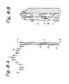
- Figs. 1 (A) and 1 (B) are a plan view and a longitudinal sectional view, respectively, of an essential portion of the flat knitting machine embodying the present invention.
- a plurality of needles 1 are arranged on a needle bed 16, each needle is operated by a connecting jack 19 connected to an actuator shaft 17.
- the needles 1 slide upward and downward for knitting.
- Sinker jacks 3 are arranged on the needle bed 16 in combination with the needles 1, respectively.
- a plate spring 4 fixed to each sinker jack 3 is in contact with the connecting jack 19 to interlock the sinker jack 3 with the connecting jack 19.
- Each sinker jack 3 is guided by an upper guide member 2 and a lower guide member 5, which are disposed on the needle bed 16, for sliding movement between an upper stopper 6 and a lower stopper 7.
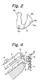
- Rocking sinkers 8 are supported pivotally on the upper end of the needle bed 16 with pins 9.
- Each rocking sinker 8 has a circular joint head 8b (Fig. 2) fitted in a recess formed in the upper end of the sinker jack 3. The rocking sinker 8 is turned in opposite directions on the pin 9 by the sinker jack 3.
- the rocking sinker 8 has a hole 8a receiving the pin 9, the circular joint head 8b fitted in the recess of the sinker jack 3, a working edge 8c for forming a loop, a projection 8d for holding down the fabric, and a circular edge 8e having the shape of an arc of a circle.
- the projection 8d depresses the fabric, retaining the loop on the working edge 8c.
- the circular edge 8e enables the yarn to slip off the rocking sinker 8 without being caught by the rocking sinker 8 even if the traveling yarn is brought into contact with the rocking sinker 8.
- the butt 20 of the connecting jack 19 has a portion provided with serration 21, and a raised end of the plate spring 4 fixed to the sinker jack 3 is in elastic engagement with the serration 21.
- the plate spring 4 is riveted or welded to the sinker jack 3.
- the plate spring 4 and the serration 21 constitute the elastic interlocking means that engages the sinker jack 3 and the connecting jack 19 frictionally to enable the connecting jack 19 to move the sinker jack 3. If the resistance against the motion of the sinker jack 3 exceeds a certain level, the sinker jack 3 slips relative to the connecting jack 19 and only the connecting jack 19 continues to move.
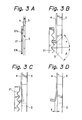
- Fig. 3(B) is an enlarged view of a portion of Fig. 3(A).
- the elastic interlocking means could transmit a force in the range of 300 to 400 gf through the serration 21 and the plate spring 4 to the sinker jack 3.
- the serration 21 of the butt 20 of the con- nectingjack 19 is in engagement with the plate spring 4 to transmit a force to the sinker jack 3 to raise the sinker jack 3, and the plate spring 4 is flexed. The force increases to a maximum immediately before the raised end of the plate spring 4 rides over a ridge of the serration 21.
- a and ⁇ are the respective inclinations of the back side and front side of each ridge of the serration 21.
- a greater force can be transmitted from the connecting jack 19 to the sinker jack 3 by the cooperative agency of the serration 21 and the plate spring 4 to the sinker jack 3 to raise the sinker jack 3 by decreasing the inclination ⁇ and to lower the sinker jack 3 by decreasing the inclination a. If it is desired to transmit an even greaterforce from the connecting jack 19 to the sinker jack 3, an initial bend represented by ⁇ in Fig.
- 3(D) may be introduced in the plate spring 4 so that the pressure of the plate spring 4 against the serration 21 is increased and the pressure of the plate spring 4 is relatively high even in a state in which the raised end of the plate spring 4 is in engagement with a furrow of the serration 21. It is also possible to increase the pressure of the plate spring 4 against the serration 21 by increasing the thickness of the plate spring 4 to increase the spring constant of the same, or the height of the ridges of the serration 21 may be increased for the same effect. If it is desired to reduce the force to be transmitted from the connecting jack 19 to the sinker jack 3, measures having an effect reverse to that of the foregoing measures for increasing the force may be taken.
- the faces of the ridges of the serration 21 in this embodiment are flat, naturally, the faces of the ridges may be curved for the same effect.
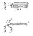
- the plate spring 4 pressing on the upper portion 21a of the serration 21 of the connecting jack 19 does not move relative to the connecting jack 19, and the sinker jack 3 moves together or simultaneously with the connecting jack 19 as the connecting jack 19 is raised until it is stopped by the upper stopper 6, when an excessively large resistance does not act against the movement of the sinker jack 3. Consequently, the rocking sinker 8 engaging the front end 10 of the sinker jack 3 is turned clockwise to its closed position to hold down the fabric 11 and to prevent raising motion of the old loop 12 as shown in Fig. 4.
- the plate spring 4 is flexed by the serration 21 of the connecting jack 19 and the ridges of the serration 21 ride over the raised end of the plate spring 4 to enable the connecting jack 19 to rise further relative to the sinker jack 3. Consequently, as shown in Figs. 5(A) and 5(B), the sinker jack 3 is retained at its uppermost position and the connecting jack 19 is raised by the actuator shaft 17 to raise the needle 1 to the clearing position C.
- the connecting jack 19 is raised to its uppermost position by the actuator shaft 17 to raise the needle 1 to the clearing position C, while the sinker jack 3 remains stopped at the position where the same has been stopped by the load on the rocking sinker 8 in holding down the fabric or in preventing the raising motion of the old loop 12 and, consequently, the fabric and the old loop 12 are not damaged.
- the plate spring 4 is in engagement with the lower portion 21 b of the serration 21 of the connecting jack 19.
- the sinker jack 3 is caused to descend togetherwith the connecting jack 19 as the latter descends as long as sinker jack 3 is stopped by the lower stopper 7 because the plate spring 4 is in engagement with the serration 21.
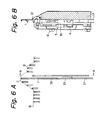
- the rocking sinker 8 engaging the upper end 10 of the sinker jack 3 is turned counterclockwise on the pin 9 toward the open position where the knitting edge 8c of the rocking sinker 8 is set at the working position as shown in Figs. 7(A) and 7(B).
- the load on the engagement of the plate spring and the serration 21 of the connecting jack 19 increases beyond a certain limit and, consequently, the ridges of the serration 21 ride over the raised end of the plate spring 4 and only the connecting jack 19 continues to descend downward relative to the sinker jack 3.
- the sinker jack 3 is held at its lowermost position by the lower stopper 7 to hold the rocking sinker at the open position, while the needle 1 is lowered via the halfway position D to the stitching position B by the connecting jack 19connected to the actuator shaft 17.
- the stitch size is dependent on the lowermost position E of the needle 1. As the needle 1 is raised from the lowermost position E via a loosening position F to the stitching position B, the rocking sinker 8 is turned from the open position toward the closed position and is turned again to the open position.
- Fig. 9 shows a portion of a flat knitting machine in accordance with the present invention having a front needle bed 16f and a back needle bed 16b respectively provided with the rocking sinkers and the associated components.
- FIGs. 10(A) and 10(B) show a portion of a flat knitting machine provided with fixed sinkers 22 and rocking sinkers disposed contiguously with the side surfaces of the fixed sinkers 22 and supported pivotally on the fixed sinkers, respectively.
- Fig. 11 shows a portion of a flat knitting machine in accordance with the present invention provided with rocking sinkers 23 supported pivotally above fixed sinkers 22, respectively.
- each rocking sinker 23 is supported with two pins 26a and 26b received respectively in a guide slot 27a and a cam slot 27b so as to be able to rock along an upper guide member 24.
- the edges of the guide slot 27a and the cam slot 27b slide relative to the pins 26a and 27b, respectively, to enable the rocking sinker 23 to rock for holding down the fabric without interfering with the fixed sinker22.
- Fig. 11 shows a state in which the needle is at the stitching position B (Fig. 1 (A)) and the rocking sinker 23 is at the open position.
- a fabric having a three-dimensional pattern was knitted by a flat knitting machine in accordance with the present invention provided with the rocking sinkers, the components associated with the rocking sinkers, and the needles individually operated by actuator shafts.
- the fabric was held down satisfactorily by the rocking sinkers and the three-dimensional pattern could be easily formed.
- the conventional cam-driven rocking sinkers are likely to apply an excessively large force to the fabric in holding down the fabric
- the rocking sinkers of the present invention did not apply an excessively large force to the fabric in holding down the fabric, did not damage the yarns and enabled the flat knitting machine to knit the fabric with high quality.
- the flat knitting machine of the present invention and the method of operating the rocking sinkers of the same flat knitting machine use the motion of the needle operating means for operating the rocking sinkers. Accordingly, the flat knitting machine need not be provided with any cams, which are necessary for operating the known rocking sinkers, and hence the flat knitting machine has a simple construction. Since the rocking sinkers of the flat knitting machine of the present invention do not apply an excessively large force to the fabric in holding down the fabric, the fabric and the yarns are not damaged, and the flat knitting machine is capable of knitting a high-quality knitted fabric.
Landscapes
- Engineering & Computer Science (AREA)
- Textile Engineering (AREA)
- Knitting Machines (AREA)
Applications Claiming Priority (2)
| Application Number | Priority Date | Filing Date | Title |
|---|---|---|---|
| JP9672492 | 1992-04-16 | ||
| JP96724/92 | 1992-04-16 |
Publications (2)
| Publication Number | Publication Date |
|---|---|
| EP0567282A1 true EP0567282A1 (fr) | 1993-10-27 |
| EP0567282B1 EP0567282B1 (fr) | 1997-09-03 |
Family
ID=14172687
Family Applications (1)
| Application Number | Title | Priority Date | Filing Date |
|---|---|---|---|
| EP93303011A Expired - Lifetime EP0567282B1 (fr) | 1992-04-16 | 1993-04-19 | Métier à tricoter rectiligne et procédé d'opération des platines basculantes du métier à tricoter rectiligne |
Country Status (6)
| Country | Link |
|---|---|
| US (1) | US5355699A (fr) |
| EP (1) | EP0567282B1 (fr) |
| KR (1) | KR930021851A (fr) |
| CN (1) | CN1084590A (fr) |
| DE (1) | DE69313505T2 (fr) |
| TW (1) | TW235315B (fr) |
Cited By (7)
| Publication number | Priority date | Publication date | Assignee | Title |
|---|---|---|---|---|
| EP0683257A1 (fr) * | 1994-05-16 | 1995-11-22 | MEC-MOR S.p.A. | Métier à tricoter circulaire à platines pour retenir le tricot |
| EP0712951A1 (fr) * | 1994-11-16 | 1996-05-22 | Tsudakoma Kogyo Kabushiki Kaisha | Dispositif d'actionnement de platines |
| DE19531960A1 (de) * | 1995-08-30 | 1997-03-06 | Schieber Universal Maschf | Flachstrickmaschine |
| EP0857802A2 (fr) * | 1997-02-07 | 1998-08-12 | H. Stoll GmbH & Co. | Métier à tricoter rectiligne |
| EP0884412A2 (fr) * | 1997-06-13 | 1998-12-16 | H. Stoll GmbH & Co. | Machine à tricoter, notamment machine à tricoter rectiligne |
| EP1522618A1 (fr) | 2003-10-07 | 2005-04-13 | H. Stoll GmbH & Co. | Platine pour un métier à tricoter rectiligne |
| US7963127B2 (en) | 2008-06-04 | 2011-06-21 | Goz-Beckert KG | Needle-drive knock-over sinker |
Families Citing this family (9)
| Publication number | Priority date | Publication date | Assignee | Title |
|---|---|---|---|---|
| JP3498270B2 (ja) * | 1994-04-28 | 2004-02-16 | 株式会社島精機製作所 | 横編機における糸案内方法及び装置 |
| TW522186B (en) * | 1999-11-17 | 2003-03-01 | Shima Seiki Mfg | Sinker device of flat knitting machine |
| CN100366807C (zh) * | 2002-05-30 | 2008-02-06 | 株式会社岛精机制作所 | 具有可动沉降装置的横机 |
| DE50309083D1 (de) * | 2003-10-07 | 2008-03-13 | Stoll & Co H | Flachstrickmaschine mit mindestens einem Nadelbett |
| SI2078073T1 (sl) * | 2006-10-12 | 2013-11-29 | Ethicon, Inc. | Celice, pridobljene iz ledvice, in postopki uporabe pri popravljanju tkiv in regeneraciji |
| KR101763848B1 (ko) | 2015-05-06 | 2017-08-14 | 주원하이텍 주식회사 | 화학약품 자동 공급시스템 |
| CN104928840B (zh) * | 2015-06-19 | 2016-09-14 | 烟台宋和科技股份有限公司 | 一种针织电子针 |
| CN107904773B (zh) * | 2017-12-13 | 2020-02-14 | 武汉纺织大学 | 无三角针织机及其编织方法 |
| US11313058B2 (en) * | 2019-02-27 | 2022-04-26 | Pai Lung Machinery Mill Co., Ltd. | Flat knitting machine structure with adjustable gap between two knock-over bits |
Citations (4)
| Publication number | Priority date | Publication date | Assignee | Title |
|---|---|---|---|---|
| DE2430824A1 (de) * | 1974-06-27 | 1976-01-08 | Harry Apprich | Vorrichtung zur herstellung einer maschenware |
| DE2545212A1 (de) * | 1975-10-09 | 1977-04-21 | Krenzler Fa Emil | Verfahren und rundstrickmaschine zur herstellung eines gestricks |
| JPH0112855B2 (fr) * | 1986-02-13 | 1989-03-02 | Asahi Chemical Ind | |
| JPH0210260B2 (fr) * | 1986-03-21 | 1990-03-07 | Haa Shutooru Gmbh Unto Co |
Family Cites Families (8)
| Publication number | Priority date | Publication date | Assignee | Title |
|---|---|---|---|---|
| DE879145C (de) * | 1951-05-29 | 1953-06-11 | Hemphill Co | Platine und Verfahren zum UEbertragen der Scheibennadelmaschen auf Rundstrickmaschinen |
| US3024633A (en) * | 1956-04-06 | 1962-03-13 | Gerhard Kochheim | Flat knitting apparatus |
| US2972242A (en) * | 1957-05-08 | 1961-02-21 | Eberl Franz | Knitting machine |
| CH485896A (de) * | 1963-11-15 | 1970-02-15 | Paliz Ag | Doppelbettstrickmaschine |
| CH416912A (de) * | 1963-11-15 | 1966-07-15 | Paliz Ag | Doppelbettstrickmaschine |
| JPS4830612A (fr) * | 1971-08-26 | 1973-04-23 | ||
| SU609801A1 (ru) * | 1977-01-03 | 1978-06-05 | Всесоюзный научно-исследовательский институт трикотажной промышленности | Плосков зальна машина |
| JPH03206161A (ja) * | 1989-12-28 | 1991-09-09 | Shima Seiki Seisakusho:Kk | 横編機におけるシンカー装置 |
-
1993
- 1993-04-14 US US08/045,700 patent/US5355699A/en not_active Expired - Fee Related
- 1993-04-15 KR KR1019930006293A patent/KR930021851A/ko not_active Application Discontinuation
- 1993-04-16 CN CN93105799A patent/CN1084590A/zh active Pending
- 1993-04-19 EP EP93303011A patent/EP0567282B1/fr not_active Expired - Lifetime
- 1993-04-19 DE DE69313505T patent/DE69313505T2/de not_active Expired - Fee Related
- 1993-04-21 TW TW082103048A patent/TW235315B/zh active
Patent Citations (4)
| Publication number | Priority date | Publication date | Assignee | Title |
|---|---|---|---|---|
| DE2430824A1 (de) * | 1974-06-27 | 1976-01-08 | Harry Apprich | Vorrichtung zur herstellung einer maschenware |
| DE2545212A1 (de) * | 1975-10-09 | 1977-04-21 | Krenzler Fa Emil | Verfahren und rundstrickmaschine zur herstellung eines gestricks |
| JPH0112855B2 (fr) * | 1986-02-13 | 1989-03-02 | Asahi Chemical Ind | |
| JPH0210260B2 (fr) * | 1986-03-21 | 1990-03-07 | Haa Shutooru Gmbh Unto Co |
Cited By (12)
| Publication number | Priority date | Publication date | Assignee | Title |
|---|---|---|---|---|
| EP0683257A1 (fr) * | 1994-05-16 | 1995-11-22 | MEC-MOR S.p.A. | Métier à tricoter circulaire à platines pour retenir le tricot |
| EP0712951A1 (fr) * | 1994-11-16 | 1996-05-22 | Tsudakoma Kogyo Kabushiki Kaisha | Dispositif d'actionnement de platines |
| US5570592A (en) * | 1994-11-16 | 1996-11-05 | Tsudakoma Kogyo Kabushiki Kaisha | Sinker actuating apparatus having spring force advancing member |
| DE19531960A1 (de) * | 1995-08-30 | 1997-03-06 | Schieber Universal Maschf | Flachstrickmaschine |
| EP0857802A2 (fr) * | 1997-02-07 | 1998-08-12 | H. Stoll GmbH & Co. | Métier à tricoter rectiligne |
| EP0857802A3 (fr) * | 1997-02-07 | 1999-05-06 | H. Stoll GmbH & Co. | Métier à tricoter rectiligne |
| EP0884412A2 (fr) * | 1997-06-13 | 1998-12-16 | H. Stoll GmbH & Co. | Machine à tricoter, notamment machine à tricoter rectiligne |
| EP0884412A3 (fr) * | 1997-06-13 | 1999-12-08 | H. Stoll GmbH & Co. | Machine à tricoter, notamment machine à tricoter rectiligne |
| US6092396A (en) * | 1997-06-13 | 2000-07-25 | H. Stoll Gmbh & Co. | Knitting machine, in particular flat knitting machine |
| DE19725073B4 (de) * | 1997-06-13 | 2004-11-25 | H. Stoll Gmbh & Co. | Strickmaschine, insbesondere Flachstrickmaschine |
| EP1522618A1 (fr) | 2003-10-07 | 2005-04-13 | H. Stoll GmbH & Co. | Platine pour un métier à tricoter rectiligne |
| US7963127B2 (en) | 2008-06-04 | 2011-06-21 | Goz-Beckert KG | Needle-drive knock-over sinker |
Also Published As
| Publication number | Publication date |
|---|---|
| TW235315B (fr) | 1994-12-01 |
| DE69313505T2 (de) | 1998-01-22 |
| CN1084590A (zh) | 1994-03-30 |
| EP0567282B1 (fr) | 1997-09-03 |
| KR930021851A (ko) | 1993-11-23 |
| US5355699A (en) | 1994-10-18 |
| DE69313505D1 (de) | 1997-10-09 |
Similar Documents
| Publication | Publication Date | Title |
|---|---|---|
| EP0567282B1 (fr) | Métier à tricoter rectiligne et procédé d'opération des platines basculantes du métier à tricoter rectiligne | |
| KR100585267B1 (ko) | 횡편기의 싱커 장치 | |
| US5345789A (en) | Apparatus for controlling displacement of yarn feeders | |
| EP0594169B1 (fr) | Métier à tricoter rectiligne avec dispositif de report | |
| EP0060888B1 (fr) | Metier a maille cueillie capable de modifier la longueur des colonnes de mailles | |
| KR960013904B1 (ko) | 횡편기에 있어서 실안내방법 및 장치 | |
| US4920767A (en) | Annular knitting machine with slide needles | |
| JPS62125053A (ja) | 横編機 | |
| US6978642B2 (en) | Weft knitting machine with movable sinker device | |
| EP0533414B1 (fr) | Métier à tricoter rectiligne | |
| US5255537A (en) | Flat-bed knitting machine | |
| JP2604677B2 (ja) | 横編機におけるトランスファージャック | |
| EP0698679B1 (fr) | Came de tricotage et serrure | |
| JP3408735B2 (ja) | トランスファージャック目移し機構を備えた横編機 | |
| EP1279758A1 (fr) | Metier a mailles cueillies avec mecanisme de report et procede de report | |
| KR101576837B1 (ko) | 가동싱커를 구비하는 횡편기 | |
| JP3155434B2 (ja) | 可動シンカーの駆動装置 | |
| US4127012A (en) | Stitch selector control means | |
| JPS6252064B2 (fr) | ||
| EP0761858B1 (fr) | Ensemble d'aiguille pour métier à tricoter | |
| US20030159473A1 (en) | Weft knitting machine with transfer mechanism and transferring method | |
| KR20070033910A (ko) | 편직 공구 | |
| JP2845506B2 (ja) | 横編地の編成方法 | |
| JP2024519163A (ja) | 編み物を製造するためのシンカー、編み装置、および編み方法 | |
| KR20020094055A (ko) | 코 이동 기구를 구비하는 횡편기 |
Legal Events
| Date | Code | Title | Description |
|---|---|---|---|
| PUAI | Public reference made under article 153(3) epc to a published international application that has entered the european phase |
Free format text: ORIGINAL CODE: 0009012 |
|
| AK | Designated contracting states |
Kind code of ref document: A1 Designated state(s): CH DE ES FR GB IT LI |
|
| 17P | Request for examination filed |
Effective date: 19940416 |
|
| 17Q | First examination report despatched |
Effective date: 19960319 |
|
| GRAG | Despatch of communication of intention to grant |
Free format text: ORIGINAL CODE: EPIDOS AGRA |
|
| GRAH | Despatch of communication of intention to grant a patent |
Free format text: ORIGINAL CODE: EPIDOS IGRA |
|
| GRAH | Despatch of communication of intention to grant a patent |
Free format text: ORIGINAL CODE: EPIDOS IGRA |
|
| GRAA | (expected) grant |
Free format text: ORIGINAL CODE: 0009210 |
|
| AK | Designated contracting states |
Kind code of ref document: B1 Designated state(s): CH DE ES FR GB IT LI |
|
| PG25 | Lapsed in a contracting state [announced via postgrant information from national office to epo] |
Ref country code: LI Free format text: LAPSE BECAUSE OF FAILURE TO SUBMIT A TRANSLATION OF THE DESCRIPTION OR TO PAY THE FEE WITHIN THE PRESCRIBED TIME-LIMIT Effective date: 19970903 Ref country code: FR Free format text: LAPSE BECAUSE OF FAILURE TO SUBMIT A TRANSLATION OF THE DESCRIPTION OR TO PAY THE FEE WITHIN THE PRESCRIBED TIME-LIMIT Effective date: 19970903 Ref country code: ES Free format text: THE PATENT HAS BEEN ANNULLED BY A DECISION OF A NATIONAL AUTHORITY Effective date: 19970903 Ref country code: CH Free format text: LAPSE BECAUSE OF FAILURE TO SUBMIT A TRANSLATION OF THE DESCRIPTION OR TO PAY THE FEE WITHIN THE PRESCRIBED TIME-LIMIT Effective date: 19970903 |
|
| REG | Reference to a national code |
Ref country code: CH Ref legal event code: EP |
|
| REF | Corresponds to: |
Ref document number: 69313505 Country of ref document: DE Date of ref document: 19971009 |
|
| ITF | It: translation for a ep patent filed |
Owner name: UFFICIO BREVETTI RICCARDI & C. |
|
| EN | Fr: translation not filed | ||
| REG | Reference to a national code |
Ref country code: CH Ref legal event code: PL |
|
| PG25 | Lapsed in a contracting state [announced via postgrant information from national office to epo] |
Ref country code: GB Free format text: LAPSE BECAUSE OF NON-PAYMENT OF DUE FEES Effective date: 19980419 |
|
| PLBE | No opposition filed within time limit |
Free format text: ORIGINAL CODE: 0009261 |
|
| STAA | Information on the status of an ep patent application or granted ep patent |
Free format text: STATUS: NO OPPOSITION FILED WITHIN TIME LIMIT |
|
| 26N | No opposition filed | ||
| GBPC | Gb: european patent ceased through non-payment of renewal fee |
Effective date: 19980419 |
|
| PG25 | Lapsed in a contracting state [announced via postgrant information from national office to epo] |
Ref country code: DE Free format text: LAPSE BECAUSE OF NON-PAYMENT OF DUE FEES Effective date: 19990202 |
|
| PG25 | Lapsed in a contracting state [announced via postgrant information from national office to epo] |
Ref country code: IT Free format text: LAPSE BECAUSE OF NON-PAYMENT OF DUE FEES;WARNING: LAPSES OF ITALIAN PATENTS WITH EFFECTIVE DATE BEFORE 2007 MAY HAVE OCCURRED AT ANY TIME BEFORE 2007. THE CORRECT EFFECTIVE DATE MAY BE DIFFERENT FROM THE ONE RECORDED. Effective date: 20050419 |