EP1522618A1 - Platine pour un métier à tricoter rectiligne - Google Patents
Platine pour un métier à tricoter rectiligne Download PDFInfo
- Publication number
- EP1522618A1 EP1522618A1 EP03022425A EP03022425A EP1522618A1 EP 1522618 A1 EP1522618 A1 EP 1522618A1 EP 03022425 A EP03022425 A EP 03022425A EP 03022425 A EP03022425 A EP 03022425A EP 1522618 A1 EP1522618 A1 EP 1522618A1
- Authority
- EP
- European Patent Office
- Prior art keywords
- board
- bed
- mesh
- hold
- circuit board
- Prior art date
- Legal status (The legal status is an assumption and is not a legal conclusion. Google has not performed a legal analysis and makes no representation as to the accuracy of the status listed.)
- Granted
Links
Images


Classifications
-
- D—TEXTILES; PAPER
- D04—BRAIDING; LACE-MAKING; KNITTING; TRIMMINGS; NON-WOVEN FABRICS
- D04B—KNITTING
- D04B15/00—Details of, or auxiliary devices incorporated in, weft knitting machines, restricted to machines of this kind
- D04B15/10—Needle beds
-
- D—TEXTILES; PAPER
- D04—BRAIDING; LACE-MAKING; KNITTING; TRIMMINGS; NON-WOVEN FABRICS
- D04B—KNITTING
- D04B15/00—Details of, or auxiliary devices incorporated in, weft knitting machines, restricted to machines of this kind
- D04B15/06—Sinkers
-
- D—TEXTILES; PAPER
- D04—BRAIDING; LACE-MAKING; KNITTING; TRIMMINGS; NON-WOVEN FABRICS
- D04B—KNITTING
- D04B15/00—Details of, or auxiliary devices incorporated in, weft knitting machines, restricted to machines of this kind
- D04B15/66—Devices for determining or controlling patterns ; Program-control arrangements
- D04B15/68—Devices for determining or controlling patterns ; Program-control arrangements characterised by the knitting instruments used
- D04B15/70—Devices for determining or controlling patterns ; Program-control arrangements characterised by the knitting instruments used in flat-bed knitting machines
-
- D—TEXTILES; PAPER
- D04—BRAIDING; LACE-MAKING; KNITTING; TRIMMINGS; NON-WOVEN FABRICS
- D04B—KNITTING
- D04B15/00—Details of, or auxiliary devices incorporated in, weft knitting machines, restricted to machines of this kind
- D04B15/88—Take-up or draw-off devices for knitting products
- D04B15/90—Take-up or draw-off devices for knitting products for flat-bed knitting machines
Definitions
- the invention relates to a circuit board of a flat knitting machine for Hold down stitches.
- Such boards of flat knitting machines are made, for example EP 0 238 797 and EP 0 424 717.
- the boards of the Flat knitting machine according to EP 0 238 797 B1 are at the same time Hold-down elements and mesh images, while the boards of the Flat knitting machine from EP 0 424 717 B1 only one Hold down function and with a rigid on the needle bed arranged mesh images interact.
- known flat knitting machines are the same disadvantages common. Both boards have only one hold down, so it is not possible to stitch both embedding and safely hold down double-bed knitted fabrics.
- EP 0 567 282 shows pivotable stitches with stitch retention hooks for flat knitting machines with a single needle drive.
- the pivoting movement of the mesh images is through translationally moved slides initiated. These sliders are with the needles frictionally connected, so they exclusively can move in the same direction to the needle.
- a Variation of the stitch retention function depending on the type the knitwear, d. H. of double or single-bed knit is also not here.
- the present invention is based on the object, the board a flat knitting machine educate so that holding down of mesh single-bed and double-bed knitted fabrics in optimal Way is possible.
- This task is solved by a board, which several Has mesh retaining surfaces. This embodiment ensures it, that regardless of whether a single or double-bed knitted fabric is created, one of the mesh holddown surfaces is able to function the safe To take over stitches.
- the additional hold downs can also be a Fulfill a backup function, if a scam but once from should solve the deepest holddown. This mesh will then detected by one of the following surfaces. This danger of Slipping off the hold-down surface is especially at given large meshes, as these are only low voltage abut the holddown surfaces.
- the plurality of mesh holddown surfaces may relate to the Rotary axes of the boards a substantially radial orientation exhibit. However, they can also be designed hook-shaped.
- the axis of rotation of the board can preferably above the Needle shafts can be arranged. Also by this measure can be improve the hold down effect of the board, as the Maschenniederhalte vom at relatively high on the needle bed arranged rotary axes, the mesh legs in the lower Include pivot position better.
- the boards can more Mesh holddown surfaces and at least one mesh canvas exhibit. They combine both the hold-down and the Meshing function in itself.
- the boards only have multiple mesh holddown surfaces and with stitches rigidly attached to the needle beds interact.
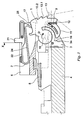
- FIG. 1 shows an apparatus 100 of a flat knitting machine for holding down and forming stitches. From the flat knitting machine, a needle bed 4 is shown in the needles 7 are guided longitudinally displaceable in grooves 41 . The groove bottom is marked 42 . At the front end, the needle bed 4 grooves 43 for receiving board guide pieces 3 on which boards 1 are pivotally guided.
- the board guide pieces 3 have for this purpose a circular recess 31 into which a circular segment 14 of the board 1 engages. In this way, the circuit board 1 about the rotational axis 18 in the direction of arrow D and in the opposite direction D ' pivotally limited.
- the stop surface 33 of the sinker guide piece 3 limits the opening movement of the board 1 in the direction of arrow D and the surface 34, the movement down in the direction of arrow D '.
- the stitching wire 45 for the stitches is passed through slots 19 in all boards 1.
- the circuit board 1 has a functional surface 11 for forming stitches, an active surface 12 for holding down loops of single-bed knitted fabrics and further active surfaces 13 , 13.1 , 13.2 for holding down loops of the opposing needle bed in double-bed knit fabrics in flat knitting machines with two needle beds.
- the pivoting movement of the board 1 in the direction of arrow D or D ' is triggered by a spring element 2 .
- This spring element 2 is guided in a cylinder disposed above the needle bed 4 slider bed. 6
- the slide bed 6 has longitudinal grooves 61 into which the spring elements 2 are inserted.
- the spring element 2 has a U-shaped spiral spring section with legs 22, 24 .
- the free leg 24 is bent in the section 25 to the outside.
- the spring element 2 engages the circuit board 1.
- the section 25 is doing on the surface 16 of the board 1 at.
- the surface 17 of the board 1 is acted upon by the spring element section 25.
- the displacement is triggered by lock parts of the carriage of the flat knitting machine, which engage a foot 21 of the spring element 2.
- the slide bed 6 is connected via a connecting bar 5 with the needle bed 4.
- the connecting strip 5 has two dovetail-shaped sections 51, 52 which engage in correspondingly shaped grooves on the needle bed 4 and the slide bed 6, respectively.
- the displacement movement of the spring element 2 is limited by a wire 63 , which is guided in a slot 23 of the spring element 2. Via the section 25, a displacement movement of the spring element 2 is translated into a rotational movement of the board 1.
- the portion 25 of the spring element 2 engages at a distance from the axis of rotation 18 of the board, which is less than the distance of the hold-down surface 12 to the axis of rotation 18th
- Fig. 2 shows, in contrast to FIG. 1, in which the circuit board 1 is shown in its off-mode, the board 1 in its fully closed position in which it retains a mesh leg 9 of the needle 7 with the surface 12.
- the board 1 has been so far swiveled in the direction of rotation D 'until its surface 16 rests against a stop surface 34 of the blanking guide piece 3.
- the spring element has been moved to trigger this rotational movement of the board 1 in the direction of arrow X maximum forward.
- the section 25 of the spring element 2 now engages the surface 17.
- the board 1 can move in the direction of arrow D against the spring force of the spring element 2 limited move upwards.
- the position of the board 1 is shown for large meshes 9, which does not pull the board 1 against the spring force upwards. Should the stitch 9 detach from the surface 12, it could be recaptured by one of the surfaces 13 to 13.2.
- FIG. 3 shows the arrangement of FIG. 2 while holding down small stitches 9.
- the board 1 has now been pivoted against the direction of the arrow D 'and against the force of the spring 2 upwards.
- the pivoting movement is limited by the spring element 2 itself.
- the free leg 24 of the U-shaped spiral spring portion is now on the leg 22 at.
- Another Nachobenex the board 1 through the mesh 9 is therefore excluded.
- the additional surfaces 13 to 13.2 fulfill a backup function.
- the spring element 2 is in the grooves 61 of the valve bed 6 with Friction led. This causes it in every slider position retains its position when the lock parts stop it apply. This allows all the spring elements 2 and so that the boards 1 in a defined pivot position being held.
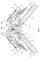
- FIG. 4 shows in cross section a device 200 for holding down loops of a flat knitting machine with two needle beds 4, 4 '.
- Each of the needle beds is in the illustrated example with boards 1, 1 ', spring elements 2, 2' and knitting needles 7, 7 ', as shown in Fig. 1, equipped.
- the device 101 for holding down stitches of the second needle bed 4 ' is identical to the device 100 of the needle bed 4.
- the effect of Hold-down surface 12, 12 ' limited.
- the board 1 of the front needle bed 4 additional functional surfaces 13, 13.1, 13.2 and the board 1 'of the rear needle bed 4' additional functional surfaces 13 ', 13.1', 13.2 ' on.
- These functional surfaces grasp the mesh legs 9 'of the stitches which are located on the shaft of the needles 7, 7' lying opposite them and hold them back when the needles 7, 7 ' carry out their advancing movement.
- the functional surface 13 of the board 1 of the front needle bed 4 has grasped the loop leg 9 'of the needle 7' of the rear needle bed 4 '.
Landscapes
- Engineering & Computer Science (AREA)
- Textile Engineering (AREA)
- Knitting Machines (AREA)
Priority Applications (5)
| Application Number | Priority Date | Filing Date | Title |
|---|---|---|---|
| EP03022425A EP1522618B1 (fr) | 2003-10-07 | 2003-10-07 | Platine pour un métier à tricoter rectiligne |
| DE50313476T DE50313476D1 (de) | 2003-10-07 | 2003-10-07 | Platine einer Flachstrickmaschine |
| TW093128375A TWI274796B (en) | 2003-10-07 | 2004-09-20 | Sinker of a flat knitting machine |
| JP2004314745A JP4022906B2 (ja) | 2003-10-07 | 2004-10-01 | 横編機のシンカ |
| CNB2004100835799A CN100451199C (zh) | 2003-10-07 | 2004-10-08 | 一种针织平机的沉降片 |
Applications Claiming Priority (1)
| Application Number | Priority Date | Filing Date | Title |
|---|---|---|---|
| EP03022425A EP1522618B1 (fr) | 2003-10-07 | 2003-10-07 | Platine pour un métier à tricoter rectiligne |
Publications (2)
| Publication Number | Publication Date |
|---|---|
| EP1522618A1 true EP1522618A1 (fr) | 2005-04-13 |
| EP1522618B1 EP1522618B1 (fr) | 2011-02-16 |
Family
ID=34306847
Family Applications (1)
| Application Number | Title | Priority Date | Filing Date |
|---|---|---|---|
| EP03022425A Expired - Lifetime EP1522618B1 (fr) | 2003-10-07 | 2003-10-07 | Platine pour un métier à tricoter rectiligne |
Country Status (5)
| Country | Link |
|---|---|
| EP (1) | EP1522618B1 (fr) |
| JP (1) | JP4022906B2 (fr) |
| CN (1) | CN100451199C (fr) |
| DE (1) | DE50313476D1 (fr) |
| TW (1) | TWI274796B (fr) |
Cited By (3)
| Publication number | Priority date | Publication date | Assignee | Title |
|---|---|---|---|---|
| US8381550B1 (en) | 2011-09-19 | 2013-02-26 | Pai Lung Machinery Mill Co., Ltd. | Needle bed structure for flat knitting machines |
| EP2423363A4 (fr) * | 2009-04-23 | 2013-03-06 | Shima Seiki Mfg | Métier à mailles cueillies équipé d'une platine mobile |
| EP2570533A1 (fr) | 2011-09-16 | 2013-03-20 | Pai Lung Machinery Mill Co., Ltd. | Structure de lit pour machines de tricotage rectiligne |
Families Citing this family (4)
| Publication number | Priority date | Publication date | Assignee | Title |
|---|---|---|---|---|
| DE502007005970D1 (de) * | 2007-09-25 | 2011-01-27 | Stoll H Gmbh & Co Kg | Flachstrickmaschine mit Abstreifplatinen |
| CN102995268A (zh) * | 2011-09-14 | 2013-03-27 | 佰龙机械厂股份有限公司 | 横式编织机的下压网眼机构及其沉降片 |
| EP2570531B1 (fr) | 2011-09-15 | 2014-03-05 | Pai Lung Machinery Mill Co., Ltd. | Mécanisme de maille pressant vers le bas et sa platine pour machines de tricotage rectiligne |
| US8468855B2 (en) | 2011-09-16 | 2013-06-25 | Pai Lung Machinery Mill Co., Ltd. | Downward pressing mesh mechanism and sinker thereof for flat knitting machines |
Citations (7)
| Publication number | Priority date | Publication date | Assignee | Title |
|---|---|---|---|---|
| US2774233A (en) * | 1952-07-12 | 1956-12-18 | Lombardi Vincent | Knitted terry fabrics |
| FR1207319A (fr) | 1957-11-11 | 1960-02-16 | Métier à tricoter à main | |
| DE1137825B (de) | 1956-11-23 | 1962-10-11 | Franz Eberl | Handflachstrickgeraet |
| US3362195A (en) | 1964-07-28 | 1968-01-09 | Goisis Mario | Method of and apparatus for forming loops in flat knitting machines |
| EP0238797A1 (fr) | 1986-03-21 | 1987-09-30 | H. Stoll GmbH & Co. | Métier à tricoter rectiligne à deux fontures avec des platines entre les aiguilles |
| EP0424717A1 (fr) | 1989-10-27 | 1991-05-02 | H. Stoll GmbH & Co. | Machine à tricoter rectiligne |
| EP0567282A1 (fr) | 1992-04-16 | 1993-10-27 | Tsudakoma Kogyo Kabushiki Kaisha | Métier à tricoter rectiligne et procédé d'opération des platines basculantes du métier à tricoter rectiligne |
Family Cites Families (2)
| Publication number | Priority date | Publication date | Assignee | Title |
|---|---|---|---|---|
| JPS4912858Y1 (fr) * | 1966-11-13 | 1974-03-29 | ||
| JPS6156966U (fr) * | 1984-09-20 | 1986-04-16 |
-
2003
- 2003-10-07 EP EP03022425A patent/EP1522618B1/fr not_active Expired - Lifetime
- 2003-10-07 DE DE50313476T patent/DE50313476D1/de not_active Expired - Lifetime
-
2004
- 2004-09-20 TW TW093128375A patent/TWI274796B/zh not_active IP Right Cessation
- 2004-10-01 JP JP2004314745A patent/JP4022906B2/ja not_active Expired - Fee Related
- 2004-10-08 CN CNB2004100835799A patent/CN100451199C/zh not_active Expired - Lifetime
Patent Citations (9)
| Publication number | Priority date | Publication date | Assignee | Title |
|---|---|---|---|---|
| US2774233A (en) * | 1952-07-12 | 1956-12-18 | Lombardi Vincent | Knitted terry fabrics |
| DE1137825B (de) | 1956-11-23 | 1962-10-11 | Franz Eberl | Handflachstrickgeraet |
| FR1207319A (fr) | 1957-11-11 | 1960-02-16 | Métier à tricoter à main | |
| US3362195A (en) | 1964-07-28 | 1968-01-09 | Goisis Mario | Method of and apparatus for forming loops in flat knitting machines |
| EP0238797A1 (fr) | 1986-03-21 | 1987-09-30 | H. Stoll GmbH & Co. | Métier à tricoter rectiligne à deux fontures avec des platines entre les aiguilles |
| EP0238797B1 (fr) | 1986-03-21 | 1989-10-04 | H. Stoll GmbH & Co. | Métier à tricoter rectiligne à deux fontures avec des platines entre les aiguilles |
| EP0424717A1 (fr) | 1989-10-27 | 1991-05-02 | H. Stoll GmbH & Co. | Machine à tricoter rectiligne |
| EP0424717B1 (fr) | 1989-10-27 | 1994-03-30 | H. Stoll GmbH & Co. | Machine à tricoter rectiligne |
| EP0567282A1 (fr) | 1992-04-16 | 1993-10-27 | Tsudakoma Kogyo Kabushiki Kaisha | Métier à tricoter rectiligne et procédé d'opération des platines basculantes du métier à tricoter rectiligne |
Cited By (3)
| Publication number | Priority date | Publication date | Assignee | Title |
|---|---|---|---|---|
| EP2423363A4 (fr) * | 2009-04-23 | 2013-03-06 | Shima Seiki Mfg | Métier à mailles cueillies équipé d'une platine mobile |
| EP2570533A1 (fr) | 2011-09-16 | 2013-03-20 | Pai Lung Machinery Mill Co., Ltd. | Structure de lit pour machines de tricotage rectiligne |
| US8381550B1 (en) | 2011-09-19 | 2013-02-26 | Pai Lung Machinery Mill Co., Ltd. | Needle bed structure for flat knitting machines |
Also Published As
| Publication number | Publication date |
|---|---|
| CN1605672A (zh) | 2005-04-13 |
| CN100451199C (zh) | 2009-01-14 |
| DE50313476D1 (de) | 2011-03-31 |
| TW200516185A (en) | 2005-05-16 |
| TWI274796B (en) | 2007-03-01 |
| JP2005113366A (ja) | 2005-04-28 |
| JP4022906B2 (ja) | 2007-12-19 |
| EP1522618B1 (fr) | 2011-02-16 |
Similar Documents
| Publication | Publication Date | Title |
|---|---|---|
| DE69017171T2 (de) | Platinenvorrichtung für Flachstrickmaschinen. | |
| DE69528087T2 (de) | Schloss für Rundstrickmaschine und Verfahren zum Verstellen der Nocken | |
| DE3827265C2 (fr) | ||
| DE19704644B4 (de) | Flachstrickmaschine und Verfahren zur Herstellung eines Gestricks | |
| EP2843095A1 (fr) | Métier à tricoter rectiligne doté de guide-fils mobiles transversalement par rapport à la planche d'aiguilles | |
| EP1522617B1 (fr) | Métier à tricoter rectiligne comprenant au moins une fonture | |
| DE4102207A1 (de) | Flachstrickmaschine | |
| EP1522618B1 (fr) | Platine pour un métier à tricoter rectiligne | |
| EP2141271B1 (fr) | Métier à tricoter rectiligne avec dispositif d'étirage de tricot | |
| DE102010017946B4 (de) | Schlosssystem für eine Flachstrickmaschine | |
| DE102009040739A1 (de) | Verfahren und Strickmaschine zur Herstellung von Strickwaren mit Ringelmustern | |
| DE1919533A1 (de) | Vorrichtung zur Zufuehrung des Fadens fuer die Streifenbildung bei Doppelzylinder-Strickmaschinen | |
| DE2930824C2 (de) | Häkelgalonmaschine | |
| DE2933841A1 (de) | Einrichtung fuer eine maschine fuer die herstellung flaechenhafter textilien, mit einem um eine schwenkachse schwenkbaren fadenfuehrer oder fadenumlenkorgan und verfahren zum betrieb der einrichtung | |
| DE69710129T2 (de) | Haken für Einzylinder-Rundstrickmaschine oder Strumpfstrickmaschine mit Zylinder und kreisförmigem oder halbkreisförmigem Nadelteller | |
| DE19954477A1 (de) | Verfahren und Vorrichtung zum Umhängen von Maschen auf einer Strickmaschine | |
| EP1467010A1 (fr) | Métier à tricoter rectiligne avec au moins deux fontures | |
| EP2381021B1 (fr) | Aiguille à tricoter pour machines à tricoter | |
| DE2656824A1 (de) | Mustereinrichtung an einer strickmaschine | |
| EP1464746B1 (fr) | Aiguille pour métiers à tricoter et procédé pour la partition d'une maille | |
| EP2034063B1 (fr) | Machine à tricoter rectiligne | |
| EP2666896B1 (fr) | Machine à tricoter rectiligne dotée d'éléments de découpe | |
| EP1757721B1 (fr) | Aiguille de transfert et méthode pour le transfert de maille | |
| DE1560922C3 (de) | Flachstrickmaschine | |
| DE2805120A1 (de) | Reissverschlusskette |
Legal Events
| Date | Code | Title | Description |
|---|---|---|---|
| PUAI | Public reference made under article 153(3) epc to a published international application that has entered the european phase |
Free format text: ORIGINAL CODE: 0009012 |
|
| AK | Designated contracting states |
Kind code of ref document: A1 Designated state(s): AT BE BG CH CY CZ DE DK EE ES FI FR GB GR HU IE IT LI LU MC NL PT RO SE SI SK TR |
|
| AX | Request for extension of the european patent |
Extension state: AL LT LV MK |
|
| 17P | Request for examination filed |
Effective date: 20050930 |
|
| AKX | Designation fees paid |
Designated state(s): DE IT TR |
|
| 17Q | First examination report despatched |
Effective date: 20070801 |
|
| GRAP | Despatch of communication of intention to grant a patent |
Free format text: ORIGINAL CODE: EPIDOSNIGR1 |
|
| GRAS | Grant fee paid |
Free format text: ORIGINAL CODE: EPIDOSNIGR3 |
|
| GRAA | (expected) grant |
Free format text: ORIGINAL CODE: 0009210 |
|
| AK | Designated contracting states |
Kind code of ref document: B1 Designated state(s): DE IT TR |
|
| REF | Corresponds to: |
Ref document number: 50313476 Country of ref document: DE Date of ref document: 20110331 Kind code of ref document: P |
|
| REG | Reference to a national code |
Ref country code: DE Ref legal event code: R096 Ref document number: 50313476 Country of ref document: DE Effective date: 20110331 |
|
| PLBE | No opposition filed within time limit |
Free format text: ORIGINAL CODE: 0009261 |
|
| STAA | Information on the status of an ep patent application or granted ep patent |
Free format text: STATUS: NO OPPOSITION FILED WITHIN TIME LIMIT |
|
| 26N | No opposition filed |
Effective date: 20111117 |
|
| REG | Reference to a national code |
Ref country code: DE Ref legal event code: R097 Ref document number: 50313476 Country of ref document: DE Effective date: 20111117 |
|
| PGFP | Annual fee paid to national office [announced via postgrant information from national office to epo] |
Ref country code: TR Payment date: 20120917 Year of fee payment: 10 |
|
| PGFP | Annual fee paid to national office [announced via postgrant information from national office to epo] |
Ref country code: DE Payment date: 20121019 Year of fee payment: 10 |
|
| REG | Reference to a national code |
Ref country code: DE Ref legal event code: R119 Ref document number: 50313476 Country of ref document: DE Effective date: 20140501 |
|
| PG25 | Lapsed in a contracting state [announced via postgrant information from national office to epo] |
Ref country code: DE Free format text: LAPSE BECAUSE OF NON-PAYMENT OF DUE FEES Effective date: 20140501 |
|
| PG25 | Lapsed in a contracting state [announced via postgrant information from national office to epo] |
Ref country code: TR Free format text: LAPSE BECAUSE OF NON-PAYMENT OF DUE FEES Effective date: 20131007 |
|
| PGFP | Annual fee paid to national office [announced via postgrant information from national office to epo] |
Ref country code: IT Payment date: 20191021 Year of fee payment: 17 |
|
| PG25 | Lapsed in a contracting state [announced via postgrant information from national office to epo] |
Ref country code: IT Free format text: LAPSE BECAUSE OF NON-PAYMENT OF DUE FEES Effective date: 20201007 |