EP0565508B1 - Balken zum Auftragen in einer Leimpresse - Google Patents
Balken zum Auftragen in einer Leimpresse Download PDFInfo
- Publication number
- EP0565508B1 EP0565508B1 EP93850076A EP93850076A EP0565508B1 EP 0565508 B1 EP0565508 B1 EP 0565508B1 EP 93850076 A EP93850076 A EP 93850076A EP 93850076 A EP93850076 A EP 93850076A EP 0565508 B1 EP0565508 B1 EP 0565508B1
- Authority
- EP
- European Patent Office
- Prior art keywords
- applicator
- press
- applicator beam
- pivot shaft
- size press
- Prior art date
- Legal status (The legal status is an assumption and is not a legal conclusion. Google has not performed a legal analysis and makes no representation as to the accuracy of the status listed.)
- Expired - Lifetime
Links
Images


Classifications
-
- D—TEXTILES; PAPER
- D21—PAPER-MAKING; PRODUCTION OF CELLULOSE
- D21H—PULP COMPOSITIONS; PREPARATION THEREOF NOT COVERED BY SUBCLASSES D21C OR D21D; IMPREGNATING OR COATING OF PAPER; TREATMENT OF FINISHED PAPER NOT COVERED BY CLASS B31 OR SUBCLASS D21G; PAPER NOT OTHERWISE PROVIDED FOR
- D21H23/00—Processes or apparatus for adding material to the pulp or to the paper
- D21H23/02—Processes or apparatus for adding material to the pulp or to the paper characterised by the manner in which substances are added
- D21H23/22—Addition to the formed paper
- D21H23/52—Addition to the formed paper by contacting paper with a device carrying the material
- D21H23/56—Rolls
- D21H23/58—Details thereof, e.g. surface characteristics, peripheral speed
Definitions
- the invention concerns a size press comprising a nip formed by press rolls, through which nip the paper or board web is passed and in which size press the first press roll is mounted by means of bearings permanently on the frame of the size press, whereas the other press roll is mounted on the frame of the size press by means of its bearings as displaceable by the intermediate of loading arms or equivalent, and in which size press the press rolls are provided with coating devices for the spreading of films of coating agent onto the faces of said rolls, said coating devices being mounted on applicator beams placed in the longitudinal direction of the rolls, which applicator beams are linked pivotally on the frame of the size press or on the loading arms of the displaceable roll by means of a pivot shaft longitudinal to the beam and which applicator beams are provided with pivot cylinders, by whose means the applicator beams can be pivoted between a closed position, i.e. the operating position, and an opened position, i.e. the service position.
- Fig. A1 The construction of a prior-art size press is illustrated in Fig. A1.
- the size press is denoted generally with the reference numeral 100.
- the press rolls 112,114 in the size press 100 form a nip N with each other, the paper or board web W being passed through said nip.
- the web W is guided into the nip N over the guide roll 119.
- the bearing 113 of the first press roll 112 is mounted on the frame 111 of the size press permanently, and, correspondingly, the bearing 115 of the second press roll 114 is mounted on the loading arm 116, which is fitted pivotally, by means of the articulated joint 118, on the frame 111 of the size press.
- loading cylinders 117 are fitted, by whose means the nip N can be opened and closed and by whose means the loading pressure between the rolls 112,114, i.e. the nip pressure, can be adjusted to the desired level.
- Each roll 112,114 in the size press 100 is provided with a coating device 123,123a of its own, by whose means a film of coating agent is applied onto the face of the respective roll 112,114, said film being transferred onto the web W in the roll nip N.
- the coating devices 123,123a are, each of them, mounted on an applicator beam 120,120a transverse to the machine direction.
- the applicator beam 120a of the first press roll 112 is mounted pivotally, by means of the articulated joint 121a, on the frame 111 of the size press, and further, between said applicator beam 120a and the frame 111 of the size press, pivot cylinders 122a are fitted, by whose means the applicator beam 120a can be opened and closed in relation to the roll 112.
- the coating device 123 of the second press roll 114 is mounted on an applicator beam 120 transverse to the machine direction, which beam is mounted pivotally, by means of the articulated joint 121, on the loading arm 116. Between the applicator beam 120 and the loading arm 116, pivot cylinders 122 are fitted, by whose means the applicator beam 120 can be opened and closed in relation to the second press roll 114.
- Fig. A1 the applicator beam of the second press roll 114 is illustrated in the service position by means of dashed lines and as denoted with the reference numeral 120'.
- a tending bridge 130 is provided on the machine, from which bridge the service operator 132 standing on the bridge can carry out the operations necessary on the applicator beam 120.
- the object of the present invention is to provide a solution by whose means the drawbacks described above and related to the prior art are avoided.
- the invention is characterized in that, in its cross section taken in a vertical plane in the transverse direction of the the applicator beam this beam is shaped so that at least its wall that is facing away from the corresponding press roll is curved, the distance from the curved outer face of the applicator beam to the pivot shaft being substantially equally large at every point, such that, when the applicator beam is pivoted around its pivot shaft, the distance from the curved outer face of the applicator beam to the other constructions of the press or constructions related thereto and placed close to the applicator beam, such as the tending bridge, remains substantially unchanged.
- the outer face of the applicator beam has been shaped, and the pivot point of the applicator beam has been chosen, so that, when the beam is pivoted between the operating position and the service position, the distance between the applicator beam and the structures outside the machine, such as the tending bridge, is substantially not changed.
- the cross-sectional shape of the applicator beam is shaped as an arc of a circle, and the pivot shaft is fitted substantially in the area of the centre point of the arc of a circle, in which case, when the applicator beam is pivoted, for example between the tending bridge and the applicator beam, no "closing nip" is formed, which is the case in prior-art solutions.
- the tending bridge can be placed considerably closer to the applicator beam than in prior art. This, of course, improves the servicing possibilities of the applicator beam substantially. Since, in the solution of the invention, the space between the applicator beam and the tending bridge can be dimensioned very little, the tending bridge does not have to be provided with handrails.
- Figure 1 is a fully schematic partial side view of a size press in which an applicator beam in accordance with the invention is fitted.
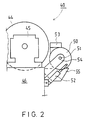
- Figure 2 is a schematic illustration of an embodiment alternative to the applicator beam illustrated in Fig. 1.
- the size press is denoted generally with the reference numeral 10.
- the press rolls 12,14 of the size press 10 form a nip N with each other, the paper or board web W being passed through said nip.
- the bearing 13 of the first press roll 12 is mounted on the frame 11 of the size press permanently, and, in a corresponding way, the bearing 15 of the second press roll 14 is mounted on a loading arm 16, which is fitted on the frame 11 of the size press pivotally by means of an articulated joint 18.
- loading cylinders 17 are fitted, by whose means the nip N can be opened and closed and by whose means the loading pressure between the rolls 12,13, i.e. the nip pressure, can be adjusted to the desired level.
- Each roll 12,14 in the size press 10 is provided with a coating device of its own, but in Fig. 1, only the coating device 23 of one of the rolls 14 in the size press is shown.
- films of coating agent are applied to the faces of the rolls 12,14, which films are transferred to the web W in the roll nip N.
- the coating device 23 is mounted on an applicator beam 20 transverse to the machine direction.
- holders 24 have been mounted on the loading arm 16, on which holders the applicator beam 20 is mounted pivotally by means of the articulated joint 21.
- a collecting trough 25 separate from the applicator beam has been arranged for the coating agent, which trough communicates with the recirculation of the coating agent.
- the applicator beam 20 in accordance with the invention is shaped as of curved cross-sectional shape as shown in Fig. 1, preferably shaped as an arc of a circle.
- the curved outer face of the applicator beam 20 is denoted with the reference numeral 26, and the radius of the curve with the reference R.
- the pivot shaft 21 is fitted in the area of the centre point of the arc of a circle, preferably exactly at the centre point, as a result of which the distance a between the applicator beam 20 and the tending bridge 30 does not change when the applicator beam 20 is pivoted.
- the tending bridge 30 can be placed very close to the applicator beam 20, because there is no risk of squeezing between the applicator beam 20 and the tending bridge 30.
- the handrail of the tending bridge which is used in connection with conventional solutions, can be omitted, and the service operator 32 has easy access to the actuating members of the applicator beam 20.
- the centre of gravity of the applicator beam 20 is placed very close to the pivot shaft 21, in which case the own weight of the applicator beam 20 does not affect the dimensioning of the pivot cylinders 22.
- the construction and installation of the tending bridge 30 can be fixed, unlike the prior-art solutions, which often require a displaceable tending bridge.
- Fig. 2 shows a solution alternative to the construction shown in Fig. 1.
- the illustration in Fig. 2 has been simplified from Fig. 1 further so that all parts not included in the scope of the invention have been omitted in the illustration in Fig. 2.
- the size press is denoted generally with the reference numeral 40.
- the press roll 44 which corresponds to the second press roll 14 in the illustration in Fig. 1, is mounted by means of bearings 45 on the loading arm 46.
- holders 54 On the loading arm 46, holders 54 have been fitted, on which the applicator beam 50 is mounted by means of a pivot shaft 51.
- the coating device is denoted fully schematically with the reference numeral 53, the coating-agent collecting trough with the reference numeral 55, and the pivot cylinders of the applicator beam 50 with the reference numeral 52.
- the embodiment shown in Fig. 2 differs from the construction shown in Fig. 1 in the respect that, in the embodiment of Fig. 2, the applicator beam 50 has been formed as of substantially fully circular cross-sectional shape.
- the pivot shaft 51 which is, in a way corresponding to Fig. 1, placed substantially at the centre point of the surface of revolution of the applicator beam 50, is placed as close to the centre of gravity of the applicator beam 50 as possible.
- the pivot cylinders 52 intended for pivoting of the applicator beam 50 can be dimensioned as of quite a small size.
Landscapes
- Coating Apparatus (AREA)
- Paper (AREA)
- Adhesives Or Adhesive Processes (AREA)
- Press Drives And Press Lines (AREA)
- Pens And Brushes (AREA)
- Decoration Of Textiles (AREA)
Claims (4)
- Leimpresse, welche einen mittels Preßwalzen (12,14;44) ausgebildeten Kniff (N) aufweist, durch welchen die Papier- oder Kartonbahn (W) geleitet wird, wobei in der Leimpresse die erste Presswalze (12) mit Hilfe von Lagerungen (13) an dem Gerüst (11) der Leimpresse ortsfest angebracht ist, wohingegen die andere Preßwalze (14;44) mit Hilfe ihrer Lagerungen (15;45), und zwar mittels Lastarmen (16;46) verstellbar, an dem Gerüst (11) der Leimpresse angebracht ist, wobei in der Leimpresse die Preßwalzen (12,14;44) mit Streichvorrichtungen (23,53) zum Überziehen von Streichmittelfilmen auf den Flächen der Walzen versehen sind, wobei die Streichvorrichtungen (23;53) an Auftragebalken (20;50) angebracht sind, welche in Längsrichtung der Walzen angeordnet sind, wobei die Auftragebalken mit Hilfe einer zum Balken längs gerichteten Drehwelle (21;51) an dem Gerüst (11) der Leimpresse oder an den Lastarmen (16) der verstellbaren Walze (14) drehbar angebracht sind und die Auftragebalken mit Schwenkzylindern (22;52) versehen sind, mit deren Hilfe die Auftragebalken (20;50) zwischen einer geschlossenen Stellung, d.h. der Arbeitsstellung, und einer geöffneten Stellung, d.h. der Wartungsstellung, drehbar sind, dadurch gekennzeichnet, daß dieser Balken in seinem entlang einer vertikalen Ebene in Querrichtung zum Auftragebalken (20;50) genommenen Querschnitt derart geformt ist, daß zumindest seine von der entsprechenden Preßwalze (14;44) abgewandte Wand (26) gebogen ist, wobei der Abstand von der gebogenen Außenfläche (26) des Auftragebalkens (20;50) zur Drehwelle (21;51) bei jedem Punkt im wesentlichen gleich groß ist, so daß, wenn der Auftragebalken (20;50) um seine Drehwelle (21,51) gedreht wird, der Abstand (a) von der gebogenen Außenfläche (26) des Auftragebalkens zu den anderen Strukturen der Presse oder zu den damit in Verbindung stehenden und in der Nähe des Auftragebalkens (20;50) angeordneten Strukturen, wie etwa der Bedienbrücke (30), im wesentlichen unverändert bleibt.
- Auftragebalken nach Anspruch 1, dadurch gekennzeichnet, daß die Drehwelle (21; 51) des Auftragebalkens in dem Bereich des Zentrums der Krümmung der gebogenen Außenfläche (26) angeordnet ist.
- Auftragebalken nach einem der vorstehenden Ansprüche, dadurch gekennzeichnet, daß die gebogene Außenfläche (26) des Auftragebalkens einen Teil eines Kreisbogens ausbildet.
- Auftragebalken nach einem der vorstehenden Ansprüche, dadurch gekennzeichnet, daß die Drehwelle (21;51) im wesentlichen am Schwerpunkt des Querschnitts des Auftragebalkens (20; 50) oder in unmittelbarer Nähe zum Schwerpunkt angeordnet ist.
Applications Claiming Priority (2)
| Application Number | Priority Date | Filing Date | Title |
|---|---|---|---|
| FI921630 | 1992-04-10 | ||
| FI921630A FI93884C (fi) | 1992-04-10 | 1992-04-10 | Applikointipalkki liimapuristimessa |
Publications (2)
| Publication Number | Publication Date |
|---|---|
| EP0565508A1 EP0565508A1 (de) | 1993-10-13 |
| EP0565508B1 true EP0565508B1 (de) | 1995-04-05 |
Family
ID=8535091
Family Applications (1)
| Application Number | Title | Priority Date | Filing Date |
|---|---|---|---|
| EP93850076A Expired - Lifetime EP0565508B1 (de) | 1992-04-10 | 1993-04-07 | Balken zum Auftragen in einer Leimpresse |
Country Status (6)
| Country | Link |
|---|---|
| US (1) | US5431731A (de) |
| EP (1) | EP0565508B1 (de) |
| AT (1) | ATE120822T1 (de) |
| CA (1) | CA2093675C (de) |
| DE (1) | DE69300096T2 (de) |
| FI (1) | FI93884C (de) |
Cited By (3)
| Publication number | Priority date | Publication date | Assignee | Title |
|---|---|---|---|---|
| DE202008004114U1 (de) | 2008-03-25 | 2008-06-05 | Voith Patent Gmbh | Auftragsvorrichtung |
| DE102007034838A1 (de) | 2007-07-26 | 2009-01-29 | Voith Patent Gmbh | Auftragsvorrichtung |
| DE102009003111A1 (de) | 2009-05-14 | 2010-11-18 | Voith Patent Gmbh | Auftragsvorrichtung |
Families Citing this family (11)
| Publication number | Priority date | Publication date | Assignee | Title |
|---|---|---|---|---|
| DE4431202A1 (de) * | 1994-09-02 | 1996-03-07 | Jagenberg Papiertech Gmbh | Vorrichtung zum beidseitigen Beschichten einer Materialbahn |
| US5573593A (en) * | 1995-01-17 | 1996-11-12 | Beloit Technologies, Inc. | Coating apparatus for selectively coating either or both sides of a traveling paper web |
| DE19619250A1 (de) * | 1996-05-13 | 1997-11-20 | Voith Sulzer Papiermasch Gmbh | Vorrichtung und Verfahren zum direkten oder indirekten Auftragen eines flüssigen oder pastösen Mediums auf eine laufende Materialbahn, insbesondere aus Papier oder Karton |
| FI110848B (fi) * | 1997-05-20 | 2003-04-15 | Metso Paper Inc | Päällystimen paluukaukalo |
| DE202004021318U1 (de) * | 2004-09-29 | 2007-07-19 | Voith Patent Gmbh | Auftragsvorrichtung |
| US7823531B2 (en) * | 2005-04-11 | 2010-11-02 | Paperchine Inc. | Control apparatus |
| AU2007271717B2 (en) * | 2006-07-05 | 2013-02-21 | Ingenum Pty Ltd | Roll support and roll coating apparatus |
| DE102007027094A1 (de) * | 2007-06-12 | 2008-12-18 | Voith Patent Gmbh | Anlage zum Streichen einer Faserstoffbahn mit einem Streichmedium |
| DE102008000160A1 (de) * | 2008-01-28 | 2009-07-30 | Voith Patent Gmbh | Vorrichtung zur Verbesserung der Arbeitsbedingungen des Bedienpersonals einer Streicheinrichtung |
| US8342118B2 (en) * | 2009-06-01 | 2013-01-01 | Processing Technologies, Llc | Sheet coating system on an apparatus for extrusion forming a sheet product |
| DE102015217627B4 (de) * | 2015-09-15 | 2017-07-20 | Thyssenkrupp Ag | Bandbearbeitungsvorrichtung sowie Verfahren zur Bearbeitung eines Bands |
Family Cites Families (7)
| Publication number | Priority date | Publication date | Assignee | Title |
|---|---|---|---|---|
| US2273021A (en) * | 1940-02-28 | 1942-02-17 | American Can Co | Adhesive applying machine |
| DE2012598A1 (de) * | 1970-03-17 | 1971-10-21 | Voith Gmbh J M | Glättschaber-Streicheinrichtung |
| DE3719305C1 (de) * | 1987-06-10 | 1988-10-20 | Kleinewefers Gmbh | Schutzvorrichtung fuer den Einlaufspalt von Kalandern und anderen Walzenmaschinen |
| SE463078B (sv) * | 1988-09-27 | 1990-10-08 | Btg Kaelle Inventing Ab | Paafoeringsanordning foer en- eller tvaasidig belaeggning av en loepande bana |
| DE3838746A1 (de) * | 1988-11-15 | 1990-05-17 | Escher Wyss Gmbh | Kalander fuer die oberflaechenbehandlung von papierbahnen |
| JP2601365B2 (ja) * | 1990-04-13 | 1997-04-16 | 富士写真フイルム株式会社 | 塗布方法 |
| FI88063C (fi) * | 1990-10-12 | 1993-03-25 | Valmet Paper Machinery Inc | Anordning foer dosering av bestrykningsmedel pao ett roerligt underlag |
-
1992
- 1992-04-10 FI FI921630A patent/FI93884C/fi active
-
1993
- 1993-04-07 AT AT93850076T patent/ATE120822T1/de not_active IP Right Cessation
- 1993-04-07 DE DE69300096T patent/DE69300096T2/de not_active Expired - Fee Related
- 1993-04-07 EP EP93850076A patent/EP0565508B1/de not_active Expired - Lifetime
- 1993-04-08 CA CA002093675A patent/CA2093675C/en not_active Expired - Fee Related
- 1993-04-09 US US08/045,633 patent/US5431731A/en not_active Expired - Lifetime
Cited By (4)
| Publication number | Priority date | Publication date | Assignee | Title |
|---|---|---|---|---|
| DE102007034838A1 (de) | 2007-07-26 | 2009-01-29 | Voith Patent Gmbh | Auftragsvorrichtung |
| DE202008004114U1 (de) | 2008-03-25 | 2008-06-05 | Voith Patent Gmbh | Auftragsvorrichtung |
| DE102009003111A1 (de) | 2009-05-14 | 2010-11-18 | Voith Patent Gmbh | Auftragsvorrichtung |
| EP2258901A1 (de) | 2009-05-14 | 2010-12-08 | Voith Patent GmbH | Auftragsvorrichtung |
Also Published As
| Publication number | Publication date |
|---|---|
| CA2093675C (en) | 2005-08-16 |
| DE69300096T2 (de) | 1995-08-31 |
| US5431731A (en) | 1995-07-11 |
| FI93884B (fi) | 1995-02-28 |
| FI921630A (fi) | 1993-10-11 |
| FI93884C (fi) | 1995-06-12 |
| FI921630A0 (fi) | 1992-04-10 |
| DE69300096D1 (de) | 1995-05-11 |
| CA2093675A1 (en) | 1993-10-11 |
| ATE120822T1 (de) | 1995-04-15 |
| EP0565508A1 (de) | 1993-10-13 |
Similar Documents
| Publication | Publication Date | Title |
|---|---|---|
| EP0565508B1 (de) | Balken zum Auftragen in einer Leimpresse | |
| FI70951B (fi) | Foerfarande i presspartiet av en pappersmaskin foer utbyte av vaevnaderna och/eller valsarna samt en stomkonstruktion foerpresspartiet foer genomfoerande av foerfarandet | |
| US4375188A (en) | On-machine supercalender apparatus | |
| US5203920A (en) | Device for applying a coating composition to traveling webs of material on two web paths | |
| EP0480897B1 (de) | Vorrichtung zum Dosieren eines auf eine sich fortbewegende Unterlage aufzutragenden Mittels | |
| US4492612A (en) | Apparatus for on-machine supercalendering of paper | |
| EP0424368A1 (de) | Auf der papiermaschine montierter kalender und verfahren zur veredlung einer papierbahn | |
| EP0608206B1 (de) | Leimpresse | |
| EP0565509B1 (de) | Leimpresse | |
| US5899405A (en) | Winding machine for winding a traveling web of paper | |
| EP0561757B1 (de) | Halterung für ein Gestell für eine Stabbeschichtungsvorrichtung oder einer Streichrakel | |
| GB2304632A (en) | Guard provided at a printing machine | |
| US4949911A (en) | Winding crossbeam | |
| FI83979B (fi) | Pressdel foer en pappersmaskin. | |
| US4879002A (en) | Frame construction of the press section in a paper machine | |
| EP0340192B1 (de) | Stützelement für Druckausgleichswalze und eine Druckausgleichswalze mit Stützelementen | |
| FI91296B (fi) | Paperi- tai kartonkikoneen kalanteri | |
| FI86449B (fi) | Foerfarande och apparatur foer eliminering av barring i en kalander. | |
| SU1680849A1 (ru) | Каландр бумагоделательной машины | |
| FI91300B (fi) | Laite liimapuristimessa | |
| FI102552B (fi) | Kalanteri | |
| FI80772B (fi) | Foerfarande vid en boejningsreglerad vals och en boejningsreglerad vals. | |
| KR810002027B1 (ko) | 종이웨브 처리장치 | |
| FI92619B (fi) | Pintaliimausyksikkö liimapuristinta varten | |
| WO2001002645A1 (en) | Assembly and method for positioning rolls of a multi-nip calender |
Legal Events
| Date | Code | Title | Description |
|---|---|---|---|
| PUAI | Public reference made under article 153(3) epc to a published international application that has entered the european phase |
Free format text: ORIGINAL CODE: 0009012 |
|
| AK | Designated contracting states |
Kind code of ref document: A1 Designated state(s): AT CH DE FR GB IT LI SE |
|
| 17P | Request for examination filed |
Effective date: 19931015 |
|
| 17Q | First examination report despatched |
Effective date: 19940114 |
|
| GRAA | (expected) grant |
Free format text: ORIGINAL CODE: 0009210 |
|
| AK | Designated contracting states |
Kind code of ref document: B1 Designated state(s): AT CH DE FR GB IT LI SE |
|
| REF | Corresponds to: |
Ref document number: 120822 Country of ref document: AT Date of ref document: 19950415 Kind code of ref document: T |
|
| REF | Corresponds to: |
Ref document number: 69300096 Country of ref document: DE Date of ref document: 19950511 |
|
| ITF | It: translation for a ep patent filed |
Owner name: STUDIO CONS. BREVETTUALE S.R.L. |
|
| ET | Fr: translation filed | ||
| PLBE | No opposition filed within time limit |
Free format text: ORIGINAL CODE: 0009261 |
|
| STAA | Information on the status of an ep patent application or granted ep patent |
Free format text: STATUS: NO OPPOSITION FILED WITHIN TIME LIMIT |
|
| 26N | No opposition filed | ||
| REG | Reference to a national code |
Ref country code: GB Ref legal event code: IF02 |
|
| PGFP | Annual fee paid to national office [announced via postgrant information from national office to epo] |
Ref country code: FR Payment date: 20060411 Year of fee payment: 14 |
|
| PGFP | Annual fee paid to national office [announced via postgrant information from national office to epo] |
Ref country code: SE Payment date: 20060413 Year of fee payment: 14 |
|
| PGFP | Annual fee paid to national office [announced via postgrant information from national office to epo] |
Ref country code: CH Payment date: 20060418 Year of fee payment: 14 Ref country code: AT Payment date: 20060418 Year of fee payment: 14 |
|
| PGFP | Annual fee paid to national office [announced via postgrant information from national office to epo] |
Ref country code: DE Payment date: 20060419 Year of fee payment: 14 |
|
| PGFP | Annual fee paid to national office [announced via postgrant information from national office to epo] |
Ref country code: GB Payment date: 20060420 Year of fee payment: 14 |
|
| PGFP | Annual fee paid to national office [announced via postgrant information from national office to epo] |
Ref country code: IT Payment date: 20060430 Year of fee payment: 14 |
|
| REG | Reference to a national code |
Ref country code: CH Ref legal event code: PL |
|
| GBPC | Gb: european patent ceased through non-payment of renewal fee |
Effective date: 20070407 |
|
| PG25 | Lapsed in a contracting state [announced via postgrant information from national office to epo] |
Ref country code: DE Free format text: LAPSE BECAUSE OF NON-PAYMENT OF DUE FEES Effective date: 20071101 |
|
| PG25 | Lapsed in a contracting state [announced via postgrant information from national office to epo] |
Ref country code: CH Free format text: LAPSE BECAUSE OF NON-PAYMENT OF DUE FEES Effective date: 20070430 Ref country code: LI Free format text: LAPSE BECAUSE OF NON-PAYMENT OF DUE FEES Effective date: 20070430 Ref country code: AT Free format text: LAPSE BECAUSE OF NON-PAYMENT OF DUE FEES Effective date: 20070407 |
|
| PG25 | Lapsed in a contracting state [announced via postgrant information from national office to epo] |
Ref country code: GB Free format text: LAPSE BECAUSE OF NON-PAYMENT OF DUE FEES Effective date: 20070407 |
|
| PG25 | Lapsed in a contracting state [announced via postgrant information from national office to epo] |
Ref country code: SE Free format text: LAPSE BECAUSE OF NON-PAYMENT OF DUE FEES Effective date: 20070408 |
|
| PG25 | Lapsed in a contracting state [announced via postgrant information from national office to epo] |
Ref country code: FR Free format text: LAPSE BECAUSE OF NON-PAYMENT OF DUE FEES Effective date: 20070430 |
|
| PG25 | Lapsed in a contracting state [announced via postgrant information from national office to epo] |
Ref country code: IT Free format text: LAPSE BECAUSE OF NON-PAYMENT OF DUE FEES Effective date: 20070407 |