EP0565508B1 - Applicator beam in a size press - Google Patents
Applicator beam in a size press Download PDFInfo
- Publication number
- EP0565508B1 EP0565508B1 EP93850076A EP93850076A EP0565508B1 EP 0565508 B1 EP0565508 B1 EP 0565508B1 EP 93850076 A EP93850076 A EP 93850076A EP 93850076 A EP93850076 A EP 93850076A EP 0565508 B1 EP0565508 B1 EP 0565508B1
- Authority
- EP
- European Patent Office
- Prior art keywords
- applicator
- press
- applicator beam
- pivot shaft
- size press
- Prior art date
- Legal status (The legal status is an assumption and is not a legal conclusion. Google has not performed a legal analysis and makes no representation as to the accuracy of the status listed.)
- Expired - Lifetime
Links
Images


Classifications
-
- D—TEXTILES; PAPER
- D21—PAPER-MAKING; PRODUCTION OF CELLULOSE
- D21H—PULP COMPOSITIONS; PREPARATION THEREOF NOT COVERED BY SUBCLASSES D21C OR D21D; IMPREGNATING OR COATING OF PAPER; TREATMENT OF FINISHED PAPER NOT COVERED BY CLASS B31 OR SUBCLASS D21G; PAPER NOT OTHERWISE PROVIDED FOR
- D21H23/00—Processes or apparatus for adding material to the pulp or to the paper
- D21H23/02—Processes or apparatus for adding material to the pulp or to the paper characterised by the manner in which substances are added
- D21H23/22—Addition to the formed paper
- D21H23/52—Addition to the formed paper by contacting paper with a device carrying the material
- D21H23/56—Rolls
- D21H23/58—Details thereof, e.g. surface characteristics, peripheral speed
Definitions
- the invention concerns a size press comprising a nip formed by press rolls, through which nip the paper or board web is passed and in which size press the first press roll is mounted by means of bearings permanently on the frame of the size press, whereas the other press roll is mounted on the frame of the size press by means of its bearings as displaceable by the intermediate of loading arms or equivalent, and in which size press the press rolls are provided with coating devices for the spreading of films of coating agent onto the faces of said rolls, said coating devices being mounted on applicator beams placed in the longitudinal direction of the rolls, which applicator beams are linked pivotally on the frame of the size press or on the loading arms of the displaceable roll by means of a pivot shaft longitudinal to the beam and which applicator beams are provided with pivot cylinders, by whose means the applicator beams can be pivoted between a closed position, i.e. the operating position, and an opened position, i.e. the service position.
- Fig. A1 The construction of a prior-art size press is illustrated in Fig. A1.
- the size press is denoted generally with the reference numeral 100.
- the press rolls 112,114 in the size press 100 form a nip N with each other, the paper or board web W being passed through said nip.
- the web W is guided into the nip N over the guide roll 119.
- the bearing 113 of the first press roll 112 is mounted on the frame 111 of the size press permanently, and, correspondingly, the bearing 115 of the second press roll 114 is mounted on the loading arm 116, which is fitted pivotally, by means of the articulated joint 118, on the frame 111 of the size press.
- loading cylinders 117 are fitted, by whose means the nip N can be opened and closed and by whose means the loading pressure between the rolls 112,114, i.e. the nip pressure, can be adjusted to the desired level.
- Each roll 112,114 in the size press 100 is provided with a coating device 123,123a of its own, by whose means a film of coating agent is applied onto the face of the respective roll 112,114, said film being transferred onto the web W in the roll nip N.
- the coating devices 123,123a are, each of them, mounted on an applicator beam 120,120a transverse to the machine direction.
- the applicator beam 120a of the first press roll 112 is mounted pivotally, by means of the articulated joint 121a, on the frame 111 of the size press, and further, between said applicator beam 120a and the frame 111 of the size press, pivot cylinders 122a are fitted, by whose means the applicator beam 120a can be opened and closed in relation to the roll 112.
- the coating device 123 of the second press roll 114 is mounted on an applicator beam 120 transverse to the machine direction, which beam is mounted pivotally, by means of the articulated joint 121, on the loading arm 116. Between the applicator beam 120 and the loading arm 116, pivot cylinders 122 are fitted, by whose means the applicator beam 120 can be opened and closed in relation to the second press roll 114.
- Fig. A1 the applicator beam of the second press roll 114 is illustrated in the service position by means of dashed lines and as denoted with the reference numeral 120'.
- a tending bridge 130 is provided on the machine, from which bridge the service operator 132 standing on the bridge can carry out the operations necessary on the applicator beam 120.
- the object of the present invention is to provide a solution by whose means the drawbacks described above and related to the prior art are avoided.
- the invention is characterized in that, in its cross section taken in a vertical plane in the transverse direction of the the applicator beam this beam is shaped so that at least its wall that is facing away from the corresponding press roll is curved, the distance from the curved outer face of the applicator beam to the pivot shaft being substantially equally large at every point, such that, when the applicator beam is pivoted around its pivot shaft, the distance from the curved outer face of the applicator beam to the other constructions of the press or constructions related thereto and placed close to the applicator beam, such as the tending bridge, remains substantially unchanged.
- the outer face of the applicator beam has been shaped, and the pivot point of the applicator beam has been chosen, so that, when the beam is pivoted between the operating position and the service position, the distance between the applicator beam and the structures outside the machine, such as the tending bridge, is substantially not changed.
- the cross-sectional shape of the applicator beam is shaped as an arc of a circle, and the pivot shaft is fitted substantially in the area of the centre point of the arc of a circle, in which case, when the applicator beam is pivoted, for example between the tending bridge and the applicator beam, no "closing nip" is formed, which is the case in prior-art solutions.
- the tending bridge can be placed considerably closer to the applicator beam than in prior art. This, of course, improves the servicing possibilities of the applicator beam substantially. Since, in the solution of the invention, the space between the applicator beam and the tending bridge can be dimensioned very little, the tending bridge does not have to be provided with handrails.
- Figure 1 is a fully schematic partial side view of a size press in which an applicator beam in accordance with the invention is fitted.
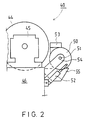
- Figure 2 is a schematic illustration of an embodiment alternative to the applicator beam illustrated in Fig. 1.
- the size press is denoted generally with the reference numeral 10.
- the press rolls 12,14 of the size press 10 form a nip N with each other, the paper or board web W being passed through said nip.
- the bearing 13 of the first press roll 12 is mounted on the frame 11 of the size press permanently, and, in a corresponding way, the bearing 15 of the second press roll 14 is mounted on a loading arm 16, which is fitted on the frame 11 of the size press pivotally by means of an articulated joint 18.
- loading cylinders 17 are fitted, by whose means the nip N can be opened and closed and by whose means the loading pressure between the rolls 12,13, i.e. the nip pressure, can be adjusted to the desired level.
- Each roll 12,14 in the size press 10 is provided with a coating device of its own, but in Fig. 1, only the coating device 23 of one of the rolls 14 in the size press is shown.
- films of coating agent are applied to the faces of the rolls 12,14, which films are transferred to the web W in the roll nip N.
- the coating device 23 is mounted on an applicator beam 20 transverse to the machine direction.
- holders 24 have been mounted on the loading arm 16, on which holders the applicator beam 20 is mounted pivotally by means of the articulated joint 21.
- a collecting trough 25 separate from the applicator beam has been arranged for the coating agent, which trough communicates with the recirculation of the coating agent.
- the applicator beam 20 in accordance with the invention is shaped as of curved cross-sectional shape as shown in Fig. 1, preferably shaped as an arc of a circle.
- the curved outer face of the applicator beam 20 is denoted with the reference numeral 26, and the radius of the curve with the reference R.
- the pivot shaft 21 is fitted in the area of the centre point of the arc of a circle, preferably exactly at the centre point, as a result of which the distance a between the applicator beam 20 and the tending bridge 30 does not change when the applicator beam 20 is pivoted.
- the tending bridge 30 can be placed very close to the applicator beam 20, because there is no risk of squeezing between the applicator beam 20 and the tending bridge 30.
- the handrail of the tending bridge which is used in connection with conventional solutions, can be omitted, and the service operator 32 has easy access to the actuating members of the applicator beam 20.
- the centre of gravity of the applicator beam 20 is placed very close to the pivot shaft 21, in which case the own weight of the applicator beam 20 does not affect the dimensioning of the pivot cylinders 22.
- the construction and installation of the tending bridge 30 can be fixed, unlike the prior-art solutions, which often require a displaceable tending bridge.
- Fig. 2 shows a solution alternative to the construction shown in Fig. 1.
- the illustration in Fig. 2 has been simplified from Fig. 1 further so that all parts not included in the scope of the invention have been omitted in the illustration in Fig. 2.
- the size press is denoted generally with the reference numeral 40.
- the press roll 44 which corresponds to the second press roll 14 in the illustration in Fig. 1, is mounted by means of bearings 45 on the loading arm 46.
- holders 54 On the loading arm 46, holders 54 have been fitted, on which the applicator beam 50 is mounted by means of a pivot shaft 51.
- the coating device is denoted fully schematically with the reference numeral 53, the coating-agent collecting trough with the reference numeral 55, and the pivot cylinders of the applicator beam 50 with the reference numeral 52.
- the embodiment shown in Fig. 2 differs from the construction shown in Fig. 1 in the respect that, in the embodiment of Fig. 2, the applicator beam 50 has been formed as of substantially fully circular cross-sectional shape.
- the pivot shaft 51 which is, in a way corresponding to Fig. 1, placed substantially at the centre point of the surface of revolution of the applicator beam 50, is placed as close to the centre of gravity of the applicator beam 50 as possible.
- the pivot cylinders 52 intended for pivoting of the applicator beam 50 can be dimensioned as of quite a small size.
Abstract
Description
- The invention concerns a size press comprising a nip formed by press rolls, through which nip the paper or board web is passed and in which size press the first press roll is mounted by means of bearings permanently on the frame of the size press, whereas the other press roll is mounted on the frame of the size press by means of its bearings as displaceable by the intermediate of loading arms or equivalent, and in which size press the press rolls are provided with coating devices for the spreading of films of coating agent onto the faces of said rolls, said coating devices being mounted on applicator beams placed in the longitudinal direction of the rolls, which applicator beams are linked pivotally on the frame of the size press or on the loading arms of the displaceable roll by means of a pivot shaft longitudinal to the beam and which applicator beams are provided with pivot cylinders, by whose means the applicator beams can be pivoted between a closed position, i.e. the operating position, and an opened position, i.e. the service position.
- The construction of a prior-art size press is illustrated in Fig. A1. In Fig. A1, the size press is denoted generally with the
reference numeral 100. The press rolls 112,114 in the size press 100 form a nip N with each other, the paper or board web W being passed through said nip. The web W is guided into the nip N over theguide roll 119. Thebearing 113 of thefirst press roll 112 is mounted on the frame 111 of the size press permanently, and, correspondingly, thebearing 115 of thesecond press roll 114 is mounted on theloading arm 116, which is fitted pivotally, by means of the articulatedjoint 118, on the frame 111 of the size press. Between the frame 111 and theloading arm 116,loading cylinders 117 are fitted, by whose means the nip N can be opened and closed and by whose means the loading pressure between the rolls 112,114, i.e. the nip pressure, can be adjusted to the desired level. - Each roll 112,114 in the
size press 100 is provided with a coating device 123,123a of its own, by whose means a film of coating agent is applied onto the face of the respective roll 112,114, said film being transferred onto the web W in the roll nip N. The coating devices 123,123a are, each of them, mounted on an applicator beam 120,120a transverse to the machine direction. In the prior-art solution shown in Fig. A1, theapplicator beam 120a of thefirst press roll 112 is mounted pivotally, by means of the articulatedjoint 121a, on the frame 111 of the size press, and further, between saidapplicator beam 120a and the frame 111 of the size press,pivot cylinders 122a are fitted, by whose means theapplicator beam 120a can be opened and closed in relation to theroll 112. In a corresponding way, thecoating device 123 of thesecond press roll 114 is mounted on anapplicator beam 120 transverse to the machine direction, which beam is mounted pivotally, by means of the articulatedjoint 121, on theloading arm 116. Between theapplicator beam 120 and theloading arm 116,pivot cylinders 122 are fitted, by whose means theapplicator beam 120 can be opened and closed in relation to thesecond press roll 114. - In the prior-
art size press 100 described above, one of the major drawbacks has been the space required by theapplicator beam 120 during pivoting of the beam between the operating position and the service position, i.e. the opened position. In Fig. A1, the applicator beam of thesecond press roll 114 is illustrated in the service position by means of dashed lines and as denoted with the reference numeral 120'. For servicing of theapplicator beam 120, atending bridge 130 is provided on the machine, from which bridge theservice operator 132 standing on the bridge can carry out the operations necessary on theapplicator beam 120. As can be seen from Fig. A1, when theapplicator beam 120 is in the operating position, there is a considerably long distance between thetending bridge 130 and theapplicator beam 120, for which reason thetending bridge 130 is provided with ahandrail 131 in order that theservice operator 132 could not even accidentally fall into the space between thetending bridge 130 and theapplicator beam 120. It has been necessary to allow said space between theapplicator beam 120 and thetending bridge 130 to remain so large, because, when theapplicator beam 120 is pivoted to the service position 120' around the articulatedjoint 121, theapplicator beam 120 is shifted a great deal closer to thetending bridge 130. This is why, and since, during pivoting, theapplicator beam 120 and thetending bridge 130 form a "closing nip", on account of working safety in relation to theapplicator beam 120, also when in the service position, and in relation to thetending bridge 130, a safety clearance b must be allowed, which is, at the minimum, of an order of 120 mm. By means of said safety clearance b, the objective has been to avoid the risk of squeezing when theapplicator beam 120 is being opened. This is why it has been necessary to dimension the distance between theapplicator beam 120 and thetending bridge 130 excessively large in view of the user, i.e. theservice operator 132. From thetending bridge 130, access to the actuating members of theapplicator beam 120 is not easy enough. - The object of the present invention is to provide a solution by whose means the drawbacks described above and related to the prior art are avoided. In view of achieving this, the invention is characterized in that, in its cross section taken in a vertical plane in the transverse direction of the the applicator beam this beam is shaped so that at least its wall that is facing away from the corresponding press roll is curved, the distance from the curved outer face of the applicator beam to the pivot shaft being substantially equally large at every point, such that, when the applicator beam is pivoted around its pivot shaft, the distance from the curved outer face of the applicator beam to the other constructions of the press or constructions related thereto and placed close to the applicator beam, such as the tending bridge, remains substantially unchanged.
- By means of the invention, a number of remarkable advantages are obtained over the prior art, in particular in consideration of the maintenance of the applicator beam. First, the outer face of the applicator beam has been shaped, and the pivot point of the applicator beam has been chosen, so that, when the beam is pivoted between the operating position and the service position, the distance between the applicator beam and the structures outside the machine, such as the tending bridge, is substantially not changed. Preferably, the cross-sectional shape of the applicator beam is shaped as an arc of a circle, and the pivot shaft is fitted substantially in the area of the centre point of the arc of a circle, in which case, when the applicator beam is pivoted, for example between the tending bridge and the applicator beam, no "closing nip" is formed, which is the case in prior-art solutions. This is why the tending bridge can be placed considerably closer to the applicator beam than in prior art. This, of course, improves the servicing possibilities of the applicator beam substantially. Since, in the solution of the invention, the space between the applicator beam and the tending bridge can be dimensioned very little, the tending bridge does not have to be provided with handrails. This also facilitates the maintenance of the applicator beam. A further advantage of the solution in accordance with the invention is provided therein that the centre of gravity of the applicator beam is placed very close to the pivot shaft of the beam, in which case the own weight of the applicator beam has no substantial effect on the size of the pivot cylinder. The further advantages and characteristic features of the invention come out from the following detailed description of the invention.
- In the following, the invention will be described by way of example with reference to the figures in the accompanying drawing.
- Figure 1 is a fully schematic partial side view of a size press in which an applicator beam in accordance with the invention is fitted.
- Figure 2 is a schematic illustration of an embodiment alternative to the applicator beam illustrated in Fig. 1.
- In Fig. 1, the size press is denoted generally with the
reference numeral 10. Thepress rolls bearing 13 of thefirst press roll 12 is mounted on theframe 11 of the size press permanently, and, in a corresponding way, the bearing 15 of thesecond press roll 14 is mounted on aloading arm 16, which is fitted on theframe 11 of the size press pivotally by means of an articulatedjoint 18. Between theframe 11 and theloading arm 16,loading cylinders 17 are fitted, by whose means the nip N can be opened and closed and by whose means the loading pressure between therolls - Each
roll size press 10 is provided with a coating device of its own, but in Fig. 1, only thecoating device 23 of one of therolls 14 in the size press is shown. By means of saidcoating devices 23, films of coating agent are applied to the faces of therolls coating device 23 is mounted on anapplicator beam 20 transverse to the machine direction. In the solution shown in Fig. 1,holders 24 have been mounted on theloading arm 16, on which holders theapplicator beam 20 is mounted pivotally by means of the articulatedjoint 21. Underneath theapplicator beam 20, a collectingtrough 25 separate from the applicator beam has been arranged for the coating agent, which trough communicates with the recirculation of the coating agent. - The
applicator beam 20 in accordance with the invention is shaped as of curved cross-sectional shape as shown in Fig. 1, preferably shaped as an arc of a circle. In Fig. 1, the curved outer face of theapplicator beam 20 is denoted with thereference numeral 26, and the radius of the curve with the reference R. Thepivot shaft 21 is fitted in the area of the centre point of the arc of a circle, preferably exactly at the centre point, as a result of which the distance a between theapplicator beam 20 and thetending bridge 30 does not change when theapplicator beam 20 is pivoted. - In such a case, the
tending bridge 30 can be placed very close to theapplicator beam 20, because there is no risk of squeezing between theapplicator beam 20 and thetending bridge 30. As is shown in Fig. 1, the handrail of the tending bridge, which is used in connection with conventional solutions, can be omitted, and theservice operator 32 has easy access to the actuating members of theapplicator beam 20. Owing to the cross-sectional shape in accordance with the invention of theapplicator beam 20, the centre of gravity of theapplicator beam 20 is placed very close to thepivot shaft 21, in which case the own weight of theapplicator beam 20 does not affect the dimensioning of thepivot cylinders 22. Further, in a solution in accordance with the invention, the construction and installation of the tendingbridge 30 can be fixed, unlike the prior-art solutions, which often require a displaceable tending bridge. - Fig. 2 shows a solution alternative to the construction shown in Fig. 1. The illustration in Fig. 2 has been simplified from Fig. 1 further so that all parts not included in the scope of the invention have been omitted in the illustration in Fig. 2. In Fig. 2, the size press is denoted generally with the
reference numeral 40. Thepress roll 44, which corresponds to thesecond press roll 14 in the illustration in Fig. 1, is mounted by means ofbearings 45 on theloading arm 46. On theloading arm 46,holders 54 have been fitted, on which theapplicator beam 50 is mounted by means of apivot shaft 51. In Fig. 2, the coating device is denoted fully schematically with thereference numeral 53, the coating-agent collecting trough with thereference numeral 55, and the pivot cylinders of theapplicator beam 50 with thereference numeral 52. The embodiment shown in Fig. 2 differs from the construction shown in Fig. 1 in the respect that, in the embodiment of Fig. 2, theapplicator beam 50 has been formed as of substantially fully circular cross-sectional shape. This provides the additional advantage that thepivot shaft 51, which is, in a way corresponding to Fig. 1, placed substantially at the centre point of the surface of revolution of theapplicator beam 50, is placed as close to the centre of gravity of theapplicator beam 50 as possible. In such a case, thepivot cylinders 52 intended for pivoting of theapplicator beam 50 can be dimensioned as of quite a small size. - Above, the invention has been described by way of example with reference to the figures in the accompanying drawing. The invention is, however, not confined to the embodiments illustrated in the figures alone, but different alternatives of the invention may show variation within the scope of the inventive idea defined in the accompanying patent claims.
Claims (4)
- Size press comprising a nip (N) formed by press rolls (12,14;44), through which nip the paper or board web (W) is passed and in which size press the first press roll (12) is mounted by means of bearings (13) permanently on the frame (11) of the size press, whereas the other press roll (14;44) is mounted on the frame (11) of the size press by means of its bearings (15;45) as displaceable by the intermediate of loading arms (16;46), and in which size press the press rolls (12,14;44) are provided with coating devices (23,53) for the spreading of films of coating agent onto the faces of said rolls, said coating devices (23;53) being mounted on applicator beams (20;50) placed in the longitudinal direction of the rolls, which applicator beams are linked pivotally on the frame (11) of the size press or on the loading arms (16) of the displaceable roll (14) by means of a pivot shaft (21;51) longitudinal to the beam and which applicator beams are provided with pivot cylinders (22;52), by whose means the applicator beams (20;50) can be pivoted between a closed position, i.e. the operating position, and an opened position, i.e. the service position, characterized in that, in its cross section taken in a vertical plane in the transverse direction of the applicator beam (20;50) this beam is shaped so that at least its wall (26) that is facing away from the corresponding press roll (14;44) is curved, the distance from the curved outer face (26) of the applicator beam (20;50) to the pivot shaft (21;51) being substantially equally large at every point, such that, when the applicator beam (20;50) is pivoted around its pivot shaft (21,51), the distance (a) from the curved outer face (26) of the applicator beam to the other constructions of the press and constructions related thereto and placed close to the applicator beam (20;50), such as the tending bridge (30), remains substantially unchanged.
- Applicator beam as claimed in claim 1, characterized in that the pivot shaft (21;51) of the applicator beam is placed in the area of the centre of curvature of the curved outer face (26).
- Applicator beam as claimed in any of the preceding claims, characterized in that the curved outer face (26) of the applicator beam forms apart of an arc of a circle.
- Applicator beam as claimed in any of the preceding claims, characterized in that the pivot shaft (21;51) is placed substantially at the centre of gravity of the cross-section of the applicator beam (20;50) or in direct proximity of said centre of gravity.
Applications Claiming Priority (2)
| Application Number | Priority Date | Filing Date | Title |
|---|---|---|---|
| FI921630 | 1992-04-10 | ||
| FI921630A FI93884C (en) | 1992-04-10 | 1992-04-10 | Application beam in a glue press |
Publications (2)
| Publication Number | Publication Date |
|---|---|
| EP0565508A1 EP0565508A1 (en) | 1993-10-13 |
| EP0565508B1 true EP0565508B1 (en) | 1995-04-05 |
Family
ID=8535091
Family Applications (1)
| Application Number | Title | Priority Date | Filing Date |
|---|---|---|---|
| EP93850076A Expired - Lifetime EP0565508B1 (en) | 1992-04-10 | 1993-04-07 | Applicator beam in a size press |
Country Status (6)
| Country | Link |
|---|---|
| US (1) | US5431731A (en) |
| EP (1) | EP0565508B1 (en) |
| AT (1) | ATE120822T1 (en) |
| CA (1) | CA2093675C (en) |
| DE (1) | DE69300096T2 (en) |
| FI (1) | FI93884C (en) |
Cited By (3)
| Publication number | Priority date | Publication date | Assignee | Title |
|---|---|---|---|---|
| DE202008004114U1 (en) | 2008-03-25 | 2008-06-05 | Voith Patent Gmbh | applicator |
| DE102007034838A1 (en) | 2007-07-26 | 2009-01-29 | Voith Patent Gmbh | applicator |
| DE102009003111A1 (en) | 2009-05-14 | 2010-11-18 | Voith Patent Gmbh | applicator |
Families Citing this family (11)
| Publication number | Priority date | Publication date | Assignee | Title |
|---|---|---|---|---|
| DE4431202A1 (en) * | 1994-09-02 | 1996-03-07 | Jagenberg Papiertech Gmbh | Device for coating a material web on both sides |
| US5573593A (en) * | 1995-01-17 | 1996-11-12 | Beloit Technologies, Inc. | Coating apparatus for selectively coating either or both sides of a traveling paper web |
| DE19619250A1 (en) * | 1996-05-13 | 1997-11-20 | Voith Sulzer Papiermasch Gmbh | Device and method for the direct or indirect application of a liquid or pasty medium to a running material web, in particular made of paper or cardboard |
| FI110848B (en) * | 1997-05-20 | 2003-04-15 | Metso Paper Inc | Return trough in coating device |
| DE102004047238A1 (en) * | 2004-09-29 | 2006-04-13 | Voith Paper Patent Gmbh | applicator |
| US7823531B2 (en) * | 2005-04-11 | 2010-11-02 | Paperchine Inc. | Control apparatus |
| EP2035159B1 (en) * | 2006-07-05 | 2012-09-19 | Fitch Engineering Pty.Ltd. | Roll support and roll coating apparatus |
| DE102007027094A1 (en) * | 2007-06-12 | 2008-12-18 | Voith Patent Gmbh | Plant for coating a fibrous web with a coating medium |
| DE102008000160A1 (en) * | 2008-01-28 | 2009-07-30 | Voith Patent Gmbh | Device for improving the working conditions of the operators of a coating device |
| US8342118B2 (en) * | 2009-06-01 | 2013-01-01 | Processing Technologies, Llc | Sheet coating system on an apparatus for extrusion forming a sheet product |
| DE102015217627B4 (en) * | 2015-09-15 | 2017-07-20 | Thyssenkrupp Ag | Belt processing device and method for processing a belt |
Family Cites Families (7)
| Publication number | Priority date | Publication date | Assignee | Title |
|---|---|---|---|---|
| US2273021A (en) * | 1940-02-28 | 1942-02-17 | American Can Co | Adhesive applying machine |
| DE2012598A1 (en) * | 1970-03-17 | 1971-10-21 | Voith Gmbh J M | Smoothing doctor coating device |
| DE3719305C1 (en) * | 1987-06-10 | 1988-10-20 | Kleinewefers Gmbh | Protection device for the inlet nip of calenders and other roller machines |
| SE463078B (en) * | 1988-09-27 | 1990-10-08 | Btg Kaelle Inventing Ab | APPLICATION DEVICE MAKES ONE OR TWO-SIDE COATING OF A CURRENT COAT |
| DE3838746A1 (en) * | 1988-11-15 | 1990-05-17 | Escher Wyss Gmbh | Calender for the surface treatment of paper webs |
| JP2601365B2 (en) * | 1990-04-13 | 1997-04-16 | 富士写真フイルム株式会社 | Application method |
| FI88063C (en) * | 1990-10-12 | 1993-03-25 | Valmet Paper Machinery Inc | Device for dosing of coating on a moving surface |
-
1992
- 1992-04-10 FI FI921630A patent/FI93884C/en active
-
1993
- 1993-04-07 EP EP93850076A patent/EP0565508B1/en not_active Expired - Lifetime
- 1993-04-07 AT AT93850076T patent/ATE120822T1/en not_active IP Right Cessation
- 1993-04-07 DE DE69300096T patent/DE69300096T2/en not_active Expired - Fee Related
- 1993-04-08 CA CA002093675A patent/CA2093675C/en not_active Expired - Fee Related
- 1993-04-09 US US08/045,633 patent/US5431731A/en not_active Expired - Lifetime
Cited By (4)
| Publication number | Priority date | Publication date | Assignee | Title |
|---|---|---|---|---|
| DE102007034838A1 (en) | 2007-07-26 | 2009-01-29 | Voith Patent Gmbh | applicator |
| DE202008004114U1 (en) | 2008-03-25 | 2008-06-05 | Voith Patent Gmbh | applicator |
| DE102009003111A1 (en) | 2009-05-14 | 2010-11-18 | Voith Patent Gmbh | applicator |
| EP2258901A1 (en) | 2009-05-14 | 2010-12-08 | Voith Patent GmbH | Coating device |
Also Published As
| Publication number | Publication date |
|---|---|
| FI93884B (en) | 1995-02-28 |
| CA2093675A1 (en) | 1993-10-11 |
| CA2093675C (en) | 2005-08-16 |
| FI921630A (en) | 1993-10-11 |
| US5431731A (en) | 1995-07-11 |
| DE69300096D1 (en) | 1995-05-11 |
| FI93884C (en) | 1995-06-12 |
| EP0565508A1 (en) | 1993-10-13 |
| DE69300096T2 (en) | 1995-08-31 |
| ATE120822T1 (en) | 1995-04-15 |
| FI921630A0 (en) | 1992-04-10 |
Similar Documents
| Publication | Publication Date | Title |
|---|---|---|
| EP0565508B1 (en) | Applicator beam in a size press | |
| FI70951B (en) | FOERFARANDE I PRESSPARTIET AV EN PAPPERSMASKIN FOER UTBYTE AV VAEVNADERNA OCH / ELLER VALSARNA SAMT EN STOMKONSTRUKTION FOERPRESSPARTIET FOER GENOMFOERANDE AV FOERFARANDET | |
| US4375188A (en) | On-machine supercalender apparatus | |
| US5203920A (en) | Device for applying a coating composition to traveling webs of material on two web paths | |
| EP0480897B1 (en) | Device for metering of a coating agent onto a moving base | |
| US5911174A (en) | Calender | |
| EP0424368A1 (en) | On-machine calender for a paper machine and a method for finishing a paper web | |
| EP0608206B1 (en) | Size press | |
| EP0565509B1 (en) | size press | |
| US5899405A (en) | Winding machine for winding a traveling web of paper | |
| EP0561757B1 (en) | Holder for the cradle of a coating bar or for a coating blade | |
| GB2304632A (en) | Guard provided at a printing machine | |
| FI83979C (en) | Press section for a paper machine | |
| US4949911A (en) | Winding crossbeam | |
| US4879002A (en) | Frame construction of the press section in a paper machine | |
| EP0340192B1 (en) | Loading shoe for a variable-crown roll and a variable-crown roll provided with loading shoes | |
| FI91296B (en) | Calender in a paper or cardboard machine | |
| FI86449B (en) | Procedure and equipment for elimination of barring in a calender | |
| SU1680849A1 (en) | Calender section of paper-making machine | |
| FI91300B (en) | Arrangement in a sizing press | |
| FI98081C (en) | Calendar | |
| FI80772B (en) | Method in a bend-adjusted roll and a bend-adjusted roll | |
| FI92619B (en) | Surface sizing unit for size press | |
| WO2001002645A1 (en) | Assembly and method for positioning rolls of a multi-nip calender |
Legal Events
| Date | Code | Title | Description |
|---|---|---|---|
| PUAI | Public reference made under article 153(3) epc to a published international application that has entered the european phase |
Free format text: ORIGINAL CODE: 0009012 |
|
| AK | Designated contracting states |
Kind code of ref document: A1 Designated state(s): AT CH DE FR GB IT LI SE |
|
| 17P | Request for examination filed |
Effective date: 19931015 |
|
| 17Q | First examination report despatched |
Effective date: 19940114 |
|
| GRAA | (expected) grant |
Free format text: ORIGINAL CODE: 0009210 |
|
| AK | Designated contracting states |
Kind code of ref document: B1 Designated state(s): AT CH DE FR GB IT LI SE |
|
| REF | Corresponds to: |
Ref document number: 120822 Country of ref document: AT Date of ref document: 19950415 Kind code of ref document: T |
|
| REF | Corresponds to: |
Ref document number: 69300096 Country of ref document: DE Date of ref document: 19950511 |
|
| ITF | It: translation for a ep patent filed |
Owner name: STUDIO CONS. BREVETTUALE S.R.L. |
|
| ET | Fr: translation filed | ||
| PLBE | No opposition filed within time limit |
Free format text: ORIGINAL CODE: 0009261 |
|
| STAA | Information on the status of an ep patent application or granted ep patent |
Free format text: STATUS: NO OPPOSITION FILED WITHIN TIME LIMIT |
|
| 26N | No opposition filed | ||
| REG | Reference to a national code |
Ref country code: GB Ref legal event code: IF02 |
|
| PGFP | Annual fee paid to national office [announced via postgrant information from national office to epo] |
Ref country code: FR Payment date: 20060411 Year of fee payment: 14 |
|
| PGFP | Annual fee paid to national office [announced via postgrant information from national office to epo] |
Ref country code: SE Payment date: 20060413 Year of fee payment: 14 |
|
| PGFP | Annual fee paid to national office [announced via postgrant information from national office to epo] |
Ref country code: CH Payment date: 20060418 Year of fee payment: 14 Ref country code: AT Payment date: 20060418 Year of fee payment: 14 |
|
| PGFP | Annual fee paid to national office [announced via postgrant information from national office to epo] |
Ref country code: DE Payment date: 20060419 Year of fee payment: 14 |
|
| PGFP | Annual fee paid to national office [announced via postgrant information from national office to epo] |
Ref country code: GB Payment date: 20060420 Year of fee payment: 14 |
|
| PGFP | Annual fee paid to national office [announced via postgrant information from national office to epo] |
Ref country code: IT Payment date: 20060430 Year of fee payment: 14 |
|
| REG | Reference to a national code |
Ref country code: CH Ref legal event code: PL |
|
| GBPC | Gb: european patent ceased through non-payment of renewal fee |
Effective date: 20070407 |
|
| PG25 | Lapsed in a contracting state [announced via postgrant information from national office to epo] |
Ref country code: DE Free format text: LAPSE BECAUSE OF NON-PAYMENT OF DUE FEES Effective date: 20071101 |
|
| PG25 | Lapsed in a contracting state [announced via postgrant information from national office to epo] |
Ref country code: CH Free format text: LAPSE BECAUSE OF NON-PAYMENT OF DUE FEES Effective date: 20070430 Ref country code: LI Free format text: LAPSE BECAUSE OF NON-PAYMENT OF DUE FEES Effective date: 20070430 Ref country code: AT Free format text: LAPSE BECAUSE OF NON-PAYMENT OF DUE FEES Effective date: 20070407 |
|
| PG25 | Lapsed in a contracting state [announced via postgrant information from national office to epo] |
Ref country code: GB Free format text: LAPSE BECAUSE OF NON-PAYMENT OF DUE FEES Effective date: 20070407 |
|
| PG25 | Lapsed in a contracting state [announced via postgrant information from national office to epo] |
Ref country code: SE Free format text: LAPSE BECAUSE OF NON-PAYMENT OF DUE FEES Effective date: 20070408 |
|
| PG25 | Lapsed in a contracting state [announced via postgrant information from national office to epo] |
Ref country code: FR Free format text: LAPSE BECAUSE OF NON-PAYMENT OF DUE FEES Effective date: 20070430 |
|
| PG25 | Lapsed in a contracting state [announced via postgrant information from national office to epo] |
Ref country code: IT Free format text: LAPSE BECAUSE OF NON-PAYMENT OF DUE FEES Effective date: 20070407 |