EP0565373B1 - Method and apparatus for detecting and preventing fluid surge in a centrifugal compressor - Google Patents
Method and apparatus for detecting and preventing fluid surge in a centrifugal compressor Download PDFInfo
- Publication number
- EP0565373B1 EP0565373B1 EP93302766A EP93302766A EP0565373B1 EP 0565373 B1 EP0565373 B1 EP 0565373B1 EP 93302766 A EP93302766 A EP 93302766A EP 93302766 A EP93302766 A EP 93302766A EP 0565373 B1 EP0565373 B1 EP 0565373B1
- Authority
- EP
- European Patent Office
- Prior art keywords
- compressor
- surge
- speed
- pressure
- controller
- Prior art date
- Legal status (The legal status is an assumption and is not a legal conclusion. Google has not performed a legal analysis and makes no representation as to the accuracy of the status listed.)
- Expired - Lifetime
Links
- 239000012530 fluid Substances 0.000 title claims description 81
- 238000000034 method Methods 0.000 title claims description 33
- 230000001133 acceleration Effects 0.000 claims description 2
- 238000011084 recovery Methods 0.000 description 12
- 238000001514 detection method Methods 0.000 description 8
- 238000012546 transfer Methods 0.000 description 7
- 230000009471 action Effects 0.000 description 6
- 238000004891 communication Methods 0.000 description 6
- 230000006378 damage Effects 0.000 description 6
- 238000010586 diagram Methods 0.000 description 5
- 230000004044 response Effects 0.000 description 5
- 230000007423 decrease Effects 0.000 description 4
- 230000002265 prevention Effects 0.000 description 4
- 230000002441 reversible effect Effects 0.000 description 4
- 230000001276 controlling effect Effects 0.000 description 3
- 238000013021 overheating Methods 0.000 description 3
- 230000008569 process Effects 0.000 description 3
- 230000001105 regulatory effect Effects 0.000 description 3
- 238000012935 Averaging Methods 0.000 description 2
- 238000002485 combustion reaction Methods 0.000 description 2
- 230000000694 effects Effects 0.000 description 2
- 230000033228 biological regulation Effects 0.000 description 1
- 238000004364 calculation method Methods 0.000 description 1
- 230000008859 change Effects 0.000 description 1
- 238000001816 cooling Methods 0.000 description 1
- 230000008878 coupling Effects 0.000 description 1
- 238000010168 coupling process Methods 0.000 description 1
- 238000005859 coupling reaction Methods 0.000 description 1
- 230000003247 decreasing effect Effects 0.000 description 1
- 238000013461 design Methods 0.000 description 1
- 239000012467 final product Substances 0.000 description 1
- 239000000446 fuel Substances 0.000 description 1
- 239000007789 gas Substances 0.000 description 1
- 238000012886 linear function Methods 0.000 description 1
- 239000007788 liquid Substances 0.000 description 1
- 230000009467 reduction Effects 0.000 description 1
- 238000005057 refrigeration Methods 0.000 description 1
- 230000001052 transient effect Effects 0.000 description 1
Images


Classifications
-
- F—MECHANICAL ENGINEERING; LIGHTING; HEATING; WEAPONS; BLASTING
- F04—POSITIVE - DISPLACEMENT MACHINES FOR LIQUIDS; PUMPS FOR LIQUIDS OR ELASTIC FLUIDS
- F04D—NON-POSITIVE-DISPLACEMENT PUMPS
- F04D27/00—Control, e.g. regulation, of pumps, pumping installations or pumping systems specially adapted for elastic fluids
- F04D27/001—Testing thereof; Determination or simulation of flow characteristics; Stall or surge detection, e.g. condition monitoring
-
- F—MECHANICAL ENGINEERING; LIGHTING; HEATING; WEAPONS; BLASTING
- F04—POSITIVE - DISPLACEMENT MACHINES FOR LIQUIDS; PUMPS FOR LIQUIDS OR ELASTIC FLUIDS
- F04D—NON-POSITIVE-DISPLACEMENT PUMPS
- F04D27/00—Control, e.g. regulation, of pumps, pumping installations or pumping systems specially adapted for elastic fluids
- F04D27/02—Surge control
- F04D27/0207—Surge control by bleeding, bypassing or recycling fluids
-
- F—MECHANICAL ENGINEERING; LIGHTING; HEATING; WEAPONS; BLASTING
- F04—POSITIVE - DISPLACEMENT MACHINES FOR LIQUIDS; PUMPS FOR LIQUIDS OR ELASTIC FLUIDS
- F04D—NON-POSITIVE-DISPLACEMENT PUMPS
- F04D27/00—Control, e.g. regulation, of pumps, pumping installations or pumping systems specially adapted for elastic fluids
- F04D27/02—Surge control
- F04D27/0207—Surge control by bleeding, bypassing or recycling fluids
- F04D27/0223—Control schemes therefor
-
- F—MECHANICAL ENGINEERING; LIGHTING; HEATING; WEAPONS; BLASTING
- F04—POSITIVE - DISPLACEMENT MACHINES FOR LIQUIDS; PUMPS FOR LIQUIDS OR ELASTIC FLUIDS
- F04D—NON-POSITIVE-DISPLACEMENT PUMPS
- F04D27/00—Control, e.g. regulation, of pumps, pumping installations or pumping systems specially adapted for elastic fluids
- F04D27/02—Surge control
- F04D27/0207—Surge control by bleeding, bypassing or recycling fluids
- F04D27/023—Details or means for fluid extraction
-
- F—MECHANICAL ENGINEERING; LIGHTING; HEATING; WEAPONS; BLASTING
- F04—POSITIVE - DISPLACEMENT MACHINES FOR LIQUIDS; PUMPS FOR LIQUIDS OR ELASTIC FLUIDS
- F04D—NON-POSITIVE-DISPLACEMENT PUMPS
- F04D27/00—Control, e.g. regulation, of pumps, pumping installations or pumping systems specially adapted for elastic fluids
- F04D27/02—Surge control
- F04D27/0261—Surge control by varying driving speed
-
- Y—GENERAL TAGGING OF NEW TECHNOLOGICAL DEVELOPMENTS; GENERAL TAGGING OF CROSS-SECTIONAL TECHNOLOGIES SPANNING OVER SEVERAL SECTIONS OF THE IPC; TECHNICAL SUBJECTS COVERED BY FORMER USPC CROSS-REFERENCE ART COLLECTIONS [XRACs] AND DIGESTS
- Y02—TECHNOLOGIES OR APPLICATIONS FOR MITIGATION OR ADAPTATION AGAINST CLIMATE CHANGE
- Y02B—CLIMATE CHANGE MITIGATION TECHNOLOGIES RELATED TO BUILDINGS, e.g. HOUSING, HOUSE APPLIANCES OR RELATED END-USER APPLICATIONS
- Y02B30/00—Energy efficient heating, ventilation or air conditioning [HVAC]
- Y02B30/70—Efficient control or regulation technologies, e.g. for control of refrigerant flow, motor or heating
Definitions
- This invention generally relates to centrifugal compressors, and more particularly to methods and apparatus for controlling and detecting surge within a centrifugal compressor.
- surge occurs when the flow through the compressor is suddenly reduced.
- the process of surge within a centrifugal compressor results in transient unstable flow of a working fluid within the centrifugal compressor during the surging process.
- surge is accompanied by loud objectionable noises and surge may cause structural damage and fatigue to the centrifugal compressor, either initially or during the life of the centrifugal compressor.
- surge may cause the following to occur to a centrifugal compressor: damage to centrifugal impellers, overheating and overloading of compressor bearings which may cause bearing destruction, fatigue and overheating of centrifugal compressor piping and overheating of other compressor components.
- centrifugal compressor control systems which are "reactive" to a surge process, and which merely unload the centrifugal compressor after surge occurs.
- the initial stages of surge have already occurred by the time corrective action is taken.
- the centrifugal compressor is nearly completely unloaded which thereby reduces the fluid output of the associated centrifugal compressors.
- Prior art compressor control systems have employed numerous methods for detecting surge.
- a method used in prior art devices includes the use of a flow meter, such as a venturi nozzle, which is placed in a compressor discharge conduit with appropriate signals to the control system to indicate if a flow reversal has occurred. This method typically is costly, inaccurate and causes additional system pressure losses.
- Another method employed in the prior art is premised upon the rate of rise of temperature of the working fluid at the inlet conduit to a centrifugal compressor stage. This method typically responds slower than desired.
- US-A-4 462 561 on which the preambles of claims 1 and 6 are based, discloses means for providing pressurised air in an aircraft with a compressor that is controlled to provide the requisite air mass flow and pressure levels over the conditions of variable air density and atmospheric pressure as the aircraft travels.
- US-A-4 646 534 discloses a control system for a refrigeration system compressor responsive to refrigerator conditions.
- a method of preventing fluid surge in a centrifugal compressor having an inlet valve, an inlet port, a discharge port and at least one compressor stage, the method comprising sensing ambient absolute pressure, generating a first signal corresponding to the ambient absolute pressure, sensing temperature of fluid at the inlet port of the compressor, generating a second signal corresponding to the ambient temperature, sensing a predetermined compressor setpoint discharge pressure, generating a third signal corresponding to the compressor setpoint discharge pressure, and inputting the first, second and third signals to a controller; characterised in that the controller has a characteristic map which provides compressor speeds at which fluid surge occurs at predetermined ambient conditions, and the method further comprising calculating a target compressor speed as a function of the ambient absolute pressure, the ambient temperature and the setpoint discharge pressure, the target compressor speed maintaining a predetermined minimum margin from the mapped compressor speed to prevent a fluid surge.
- a fluid surge control apparatus for a centrifugal compressor, the apparatus comprising means for sensing ambient absolute pressure and to generate a first signal corresponding to the ambient absolute pressure, means for sensing temperature of fluid at an inlet port of the compressor and for generating a second signal corresponding to the ambient temperature, means for sensing a predetermined compressor setpoint discharge pressure and for generating a third signal corresponding to the compressor setpoint discharge pressure, and a controller to receive said first, second and third signals; characterised in that the controller has a characteristic map which provides compressor speeds at which fluid surge occurs at predetermined ambient conditions, and means to calculate a target compressor speed as a function of the ambient absolute pressure, the ambient temperature and the setpoint discharge pressure so as to cause the target compressor speed to maintain a predetermined minimum margin from the mapped compressor speed to prevent a fluid surge.
- the invention also extends to a centrifugal compressor incorporating apparatus essentially as defined in the preceding paragraph.
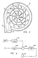
- centrifugal compressor is generally illustrated at 10 in Figure 1.
- the term centrifugal compressor applies to centrifugal pumps and centrifugal compressors, as well as any centrifugal device which displaces a working fluid, which in this specification is intended to cover any fluid including gases, typically air, or liquids by a centrifugal action.
- the centrifugal compressor 10 includes a first compressor stage 12a and a second compressor stage 12b of conventional design. Although only two compressor stages 12a, 12b are illustrated in Figure 1, anywhere from one to ten or more compressor stages may be connected for series fluid communication.
- each compressor stage 12a and 12b includes a centrifugal impeller 11 and a diffuser portion 13 through which a working fluid is discharged.
- the impeller 11, which rotates at high speeds, is aerodynamically configured to provide a fluid pressure rise which is accompanied by a characteristic fluid velocity increase.
- the diffuser portion 13 is configured in a manner well known in the art to decrease the velocity of the fluid passing from the centrifugal impeller to thereby provide an additional working fluid pressure rise.
- the compressor stages 12a and 12b are conventionally driven by a gear system 16 which is disposed in motive force receiving relation to a variable-speed prime mover 14.
- the term "prime mover” is intended to cover internal combustion engines, electric motors or any device which transmits motive force or delivers work to the compressor 10.
- a coupling (not shown) is used to connect the prime mover 14 to the compressor 10.
- Angular velocity of the prime mover 14 is sensed by an angular velocity sensor 18.
- a controller 130 performs a plurality of functions as will be explained in the paragraphs to follow.
- a microcomputer which may be used in the application as the controller 130 is the INTEL 80C196. (INTEL is a trademark of the Intel Corporation.)
- the first stage 12a and the second stage 12b are disposed in series fluid communication by an interstage conduit 15.
- An intercooler 17 and a moisture separator 19 are disposed in the interstage conduit to prepare the working fluid passing between the two stages to a condition where it can be compressed through the second stage.
- Working fluid is supplied to the first compressor stage 12a by an inlet conduit 22.
- Flow of the working fluid through the inlet conduit 22 is regulated by a suitable inlet valve or throttling device 24.
- the inlet valve 24 is regulated by the controller 130 as will be described in detail hereinafter.
- the inlet valve 24 includes a means to prevent its full closure to provide the compressor 10 a minimum flow of working fluid for non-surging operation during startup and during idle speed operation.
- the means to prevent full closure of inlet valve 24 may be either mechanical, such as a valve position stop, for example, or electrical, such as a minimum electrical signal to the inlet valve positioning system as directed by the controller 130, for example.
- a first pressure sensor or transducer 25 measures the pressure of the working fluid contained within the inlet conduit 22. As the inlet valve 24 is opened, the absolute pressure in the inlet conduit 22 increases, and the amount of working fluid the centrifugal compressor is capable of displacing increases.
- a temperature sensor 202 measures the temperature of the working fluid entering from the first stage 12a.
- Another temperature sensor 129 measures the temperature of the working fluid entering the second stage 12b.
- a second pressure sensor or transducer 32 measures fluid pressure at the discharge port 30.
- the discharge port 30 is in fluid communication with a discharge conduit 34 which is disposed in fluid supplying relation to an aftercooler 36 which returns the working fluid to a desired final temperature after the fluid exits the second stage 12b.
- the working fluid leaving the aftercooler 36 flows through a check valve 40 and into a reservoir 38 for containing pressurized working fluid.
- a pressure sensor 39 measures pressure in the reservoir 38.
- a service line 42 is disposed in fluid communication with the reservoir 38 which permits the working fluid to be supplied to an object of interest, such as a service outlet 46.
- a service valve 48 limits the application of the fluid contained within the reservoir 38 to the service outlet 46.
- the discharge port 30 is defined as being contained within the discharge conduit 34.
- a blowoff conduit 50 is disposed in fluid communication with the discharge conduit 34.
- a blowoff valve 52 Connected in fluid communication to the blowoff conduit 50 is a blowoff valve 52 which is variably positionable to permit control of fluid flow from the discharge conduit 34 to the atmosphere.
- the inlet valve 24 and the blowoff valve 52 interact with the first and second compressor stages 12a, 12b to control the fluid pressure applied to the interstage conduit 15 and the discharge conduit 34 in a manner well known in the art.
- Positioning of the blowoff valve 52 is regulated by the controller 130 using logic which is provided in Figures 3 and 13, and which is described in further detail hereinafter.
- centrifugal stages 12a, 12b for centrifugal compressors are what permits a phenomenon called surge.
- Surge is one of the primary operational limitations of centrifugal compressors. For any particular aerodynamic impeller configuration, there exists a maximum pressure ratio that the impeller is capable of producing when rotating at a particular speed with a particular working fluid condition. Surge is permitted since fluid flow is possible, under distinct times and conditions, in both a forward direction 70 and a reverse direction 72 between centrifugal impellers 12 and the discharge port 30, as illustrated by Figure 2. Surge occurrence is best understood in terms of a compressor performance map.
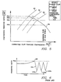
- Figure 5 provides a characteristic map of the performance achievable with a particular centrifugal compressor.
- Figure 5 is a graph of overall compressor pressure ratio versus a flow parameter used to indicate the mass flow of fluid passing through the compressor corrected for fluid conditions at the inlet to the compressor.
- Various corrected speed lines are shown on the compressor map of Figure 5 and are explained in detail hereinafter.
- FIG. 5 illustrates a "surge line" 80 at which the compressor 10 is unable to operate in the region to the left of this line.
- the surge line 80 defines a locus of upper limits of corrected speed lines, and defines a critical pressure ratio PR3.
- a speed parameter usually called “corrected speed”
- the speed parameter or "corrected speed” can be increased by either increasing physical compressor speed or by reducing the temperature of the working fluid at the compressor inlet.
- the centrifugal compressor 10 is capable of operating at higher pressure ratios before the surge line is reached.
- Figure 6 is a graph of discharge pressure versus time of a "prior art" embodiment of a centrifugal compressor which is experiencing surge, and which does not include a device or system for surge prevention, detection, control, and recovery.
- the compressor of Figure 6 initially operates in a stable condition, if a sudden decrease in compressed working fluid demand occurs, typically from service outlet 46, the compressor discharge pressure in both the reservoir 38 and the discharge conduit 34 rises.
- the term "pressure ratio”, as used herein, is defined as the quotient of the working fluid absolute pressure applied to the discharge port 30, as sensed by the discharge pressure sensor 32, divided by the working fluid absolute pressure applied to the inlet conduit 22, as sensed by the inlet pressure sensor 25. Unless otherwise specified herein, pressure sensors measure absolute pressures.
- Centrifugal impeller 11 and diffuser portion 13 combinations are capable of operating up to only a specified range of pressure ratios. If the pressure ratio is increased above a specified value, called the surge point 68 which is illustrated in Figure 6, then the centrifugal impellers are unable to maintain working fluid flow in the forward direction 70, and, in such a case, the working fluid actually flows in the reverse direction 72. Therefore, when the overall compressor ratio rises to the surge pressure ratio, (upper dashed line in Figure 5) a surge event occurs. The reversal of flow in the direction 72 accompanying the surge continues until the pressure ratio falls below a predetermined level, and then with the decreased pressure ratio, fluid flow can once again begin in the forward direction 70.
- the surge point 68 which is illustrated in Figure 6
- surge is accompanied by a sharp down spike in compressor discharge pressure which is followed by a rise in compressor discharge pressure as the compressor restabilizes.
- the surge event will continue to occur.
- the fixed volume of working fluid contained in the conduit 15 or conduit 34 will suddenly reverse flow direction, and flow backwards toward the compressor inlet conduit 22.
- the impeller reloads under the lower pressure ratio conditions, the working fluid will again move in the normal direction until the surge spike happens again.
- the series of pressure spikes 102a, 102b, 102c may be characterized as an alternating pressure wave which is transmitted through the working fluid.
- the working fluid is alternated forward and backwards as a result of the pressure spikes 102a, 102b, 102c, the energy being transferred to the working fluid by the prime mover 14 is manifested in heat with an accompanying rise in the temperature of the working fluid.
- the surge control system of the present invention overcomes the weaknesses of the prior art by preventing centrifugal compressor surge from occurring in the first instance, detecting compressor surge if it should occur, and recovering from a surge event with minimum interruption of flow to the application.
- Figure 7 is a graph of surge margin versus altitude and ambient temperature of a "prior art" embodiment of a centrifugal compressor which does not include a device for sensing and setting compressor rotational speed.
- the controller 130 continuously adjusts physical compressor speed or set point speed of the variable-speed prime mover 14 as a function of operating altitude, ambient temperature, and setpoint discharge pressure. In this manner, available surge margin is increased to that shown in Figure 8 to prevent a surge event.
- Setpoint speed is computed by the controller 130 using the following equations:
- the controller 130 utilizes a "proportional integral derivative” or “PID” control algorithm, (see Figure 3), to control and maintain the correct setpoint compressor speed.
- Figure 9 provides the control transfer functions used by controller 130 for dynamic speed control of the speed control valve 74.
- the working fluid exiting the discharge port 30 flows freely through the discharge conduit 34, aftercooler 36, check valve 40, reservoir 38, and service valve 48 to an object of interest.
- the service valve 48 is shut off, the compressor stages 12a, 12b continue to displace working fluid into these elements which causes absolute pressure in these elements to increase. If the blowoff valve 52 does not open quickly enough, the pressure increase will cause a surge event to occur accompanied by the aforementioned flow reversal and reduction of pressure ratio characterizing the surge condition.
- the apparatus of the present invention is also operable to prevent surge in the first instance by modulating the blowoff valve 52 to maintain the pressure ratio well below the critical pressure ratio PR3 where surge occurs.
- the critical pressure ratio PR3 is the surge point in Figure 5 which is defined by the intersection of a particular corrected speed line and the actual surge line.
- Figure 5 shows two additional lines 81 and 82 set at a predetermined distance away from, and generally aligned with, the actual surge line 80.
- the intersection of the corrected speed line 78 and the line 81 defines the maximum safe pressure ratio PR2.
- the controller 130 will modulate the blowoff valve 52 to maintain compressor pressure ratio at a target value slightly below the safe maximum pressure ratio of PR2. This actual target pressure ratio is defined as pressure ratio PR1 and is shown on Figure 5 as dashed line 82.
- FIG. 10 The normal modulation of the blowoff valve 52 at pressure ratio PR1 is shown in Figure 10.
- the controller 130 When the pressure ratio climbs above the safe maximum pressure ratio PR2, surge is very likely to occur or is imminent, and the controller 130 enters a reset mode wherein the blowoff valve 52 is quickly opened enough to relieve the pressure ratio rise.
- a graphic representation of this action is shown in Figure 11 where the controller 130 is initially modulating the blowoff valve 52 to maintain compressor pressure ratio at PR1. If some external event, such as the quick closing of the service valve 48, causes compressor pressure ratio to increase above the target value of PR1 to as high as PR2 (see Figure 11), the controller 130 will sense this increase in pressure ratio and cause the blowoff valve 52 to quickly open to some higher value. Opening the blowoff valve reduces the pressure of the working fluid at the discharge port 30 thereby reducing the pressure ratio. Reducing the pressure ratio in turn decreases the possibility of an occurrence of flow of working fluid in the reverse direction 72.
- the controller 130 will also perform a "speed signal reset" simultaneously with the quick opening of the blowoff valve 52. This technique prevents compressor overspeed from occurring due to the sudden load drop associated with the blowoff valve reset function. Modulation of the blowoff valve 52 to prevent compressor pressure ratio from exceeding PR1 is accomplished by a "proportional integral" or "PI" control technique in controller 130. Figures 3 and 13 provide the control transfer functions used by the controller 130 in modulating the blowoff valve 52 to achieve the target safe pressure ratio PR1.
- the present invention is operable to detect surge by analyzing compressor discharge pressure at the discharge port 30 by pressure sensor 32.
- the difference in profile of the pressure spike 102 characterizing surge and a pressure ratio profile produced by other typical compressor operation is that the drop in pressure ratio in a surge, relative to time, has an extremely sharp slope. There is no other normally occurring phenomenon in the operation of the centrifugal compressor which produces as steep a slope in pressure ratio drop as the pressure spike which accompanies surge.
- the controller 130 continually monitors compressor outlet pressure via sensor 32 and compressor inlet pressure via sensor 25. From the information generated by these pressure sensors, the controller 130 computes an overall compressor pressure ratio. When the absolute value of compressor discharge pressure drops faster than a predetermined rate, a probable surge is declared to have occurred. The controller 130 continues to monitor compressor discharge pressure to determine if the down spike in pressure signal is followed by an up spike in pressure as shown in Figure 6. When detected, the controller 130 declares that a definite surge has occurred, and the controller increments a counter to count the number of definite surges which have occurred within a certain time period. Upon the first detection of a surge event as indicated by the behavior of the compressor discharge pressure signal, the controller 130 executes surge recovery measures as described in detail hereinafter. The controller 130 is preprogrammed to permit only a certain maximum number of surge events to occur within a predetermined time period. Upon the occurrence of the maximum number of surge events, the compressor system is shutdown by the controller 130.
- the controller 130 continuously monitors the temperature of the working fluid at the inlet of stage 12a by temperature sensor 202, and the temperature of the working fluid at the inlet of stage 12b by temperature sensor 129. If either of these two temperatures rises to a predetermined maximum value, the controller 130 will shutdown the system with a message to the operator that a continuous surge event has required system shutdown. In this manner, the centrifugal compressor and associated equipment is assured of protection against damage from repeated surging.
- the controller 130 causes the blowoff valve 52 to quickly increase to a new position characterized by a larger opening angle.
- the larger blowoff valve area eliminates the surge condition and normal blowoff valve modulation is restarted based on a target compressor pressure ratio equal to PR1.
- Figure 12 characterizes this response to a surge event and the resulting recovery therefrom.
- the controller automatically decrements PR1 by a predetermined amount. For example, PR1 may be decremented by one percent 1% of its previous value when a surge event is detected.
- the controller 130 In this manner, the occurrence of a single surge event causes the controller 130 to self-correct by setting a target pressure ratio, PR1, lower than the last value.
- PR1 target pressure ratio
- the controller 130 automatically resets PR1 to an initial default value each time the controller is turned on and the system is restarted.
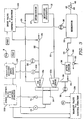
- the controller regulates the inlet valve 24, the blowoff valve 52, and the speed control valve 74 to prevent and recover from a surge event, as will be described in further detail hereinafter.
- the controller 130 receives relevant data from the following: Pressure transducer (9): Barometric pressure, psia (PT0) Pressure transducer (25): Compressor inlet pressure, psia (PT1) Pressure transducer (32): Compressor dis.
- the controller 130 receives the following data: barometric pressure (PT0) from the absolute pressure sensor 9; ambient temperature (T1) from temperature sensor 202; and setpoint pressure (PSET) from a user selection or switch selection on the operator panel 122. From this data, the controller 130 computes setpoint target speed to establish a desired minimum compressor surge margin. At a predetermined time when the compressor 10 is started, warmed up, loaded, and placed on-line, the controller 130 continuously regulates the inlet valve 24, the blowoff valve 52, and the speed control valve 74 to prevent and recover from a surge event.
- PT0 barometric pressure
- T1 ambient temperature
- PSET setpoint pressure
- the inlet valve 24 permits flow throttling, as directed by the controller 130, to achieve the desired setpoint discharge pressure PSET in the reservoir 38 as measured by pressure sensor 39, Regulation of the inlet valve 24 by the controller 130 is based upon a "proportional integral" or "PI" control technique as shown in Figures 3 and 4. As an example, for a typical 2-stage centrifugal compressor system, a flow turndown of 15% to 20% is possible by inlet valve throttling only prior to target pressure ratio, PR1, being reached.
- the blowoff valve 52 is positioned by the controller 130 in response to overall compressor pressure ratio as previously described. When the compressor pressure ratio is less than the target value of PR1, the blowoff valve 52 is fully closed. In such a position, maximum flow is provided to a user at maximum efficiency.
- the controller 130 begins to modulate the blowoff valve, through logic outlined in Figure 13, to maintain the system pressure ratio at PR1. If the compressor pressure ratio rises to the maximum safe pressure ratio of PR2, the controller 130 will cause the blowoff valve to quickly reset and open to a predetermined position to relieve discharge pressure (see Figure 11). If the compressor pressure ratio rises further to the actual surge point or critical pressure ratio, PR3, the compressor may surge and the controller will detect such surge by the rapid down spike in compressor discharge pressure. Surge recovery will then begin as shown in Figure 12 which is based on a further direct opening of the blowoff valve 52 and a return to normal blowoff valve modulation.
- the controller 130 continuously monitors the number of surges within any particular time interval, as well as the instantaneous value of the working fluid temperature at the inlet to any of the compressor stages. Should the above-described surge recovery technique fail to abort the surge for any reason, the compressor is automatically unloaded and shutdown to prohibit damage from occurring thereto.
- the controller 130 repeatedly executes a main software control loop 100 based on the flowchart shown in Figure 14.
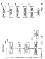
- the execution of the main software control loop is interrupted each 25 Msec to execute an interrupt control loop 120, the flowchart of which is shown in Figure 15.
- the interrupt control loop 120 includes a scan loop 122; a prime mover speed control loop 124, which is flowcharted in Figure 16; an inlet valve control loop 126, which is flowcharted in Figure 17; and a blowoff valve control loop 128, which is flowcharted in Figure 18.
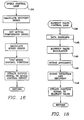
- the speed control loop 124 prevents surge by continuously controlling the rotational speed of the prime mover 14, such that the compressor surge margin is maintained at a desired level at a particular combination of altitude (PT0), ambient temperature (T1), and setpoint pressure (PSET). For example, speed may be adjusted to achieve a minimum of 8% surge margin at any full-flow operating condition.
- setpointspeed is calculated by the controller 130 as outlined above. Rotational speed is controlled using a "proportional integral differential" or "PID" control technique based on the control transfer functions depicted in Figure 9.
- the output signal to the speed control device 74 varies with the type of variable-speed prime mover 14 employed.
- the output signal generally consists of an analog signal proportional to the level of speed required by the prime mover 14.
- the signal may, as an example, be a pulse width modulated square wave signal to a rotary solenoid device connected to a fuel control valve on the engine (not shown).
- the signal may, as an example, be an analog signal to a frequency control unit for motor speed variance (not shown).
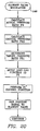
- the inlet valve control loop 126 maintains setpoint pressure by controlling the position of the inlet valve 24 to match compressor flow with actual flow demand. As shown in Figure 5, the inlet valve 24 allows compressor flow turndown from the maximum possible value at a particular rotational speed of the compressor 10, to a value corresponding to a target safe maximum operating pressure ratio.
- the target safe maximum operating compressor ratio is shown as PR1 in Figures 5, 10, 11, and 12.
- the inlet valve 24 is prevented from fully closing to prevent compressor surge from occurring during startup acceleration and while operating at warmup or unloaded idle speed.
- the method of preventing full valve closure may vary, but will generally consist of either mechanical means or electrical means.
- a mechanical means a mechanical stop may be employed that prevents full closure of the valve or throttling device 24.
- the controller 130 may have a limit on the amount of output signal, either low or high, depending on the inlet valve driver device.
- the inlet valve 24 may have a bypass area that allows a certain amount of flow to bypass the inlet valve directly to the impeller 11 of the first stage 12a of the centrifugal compressor 10. In this manner, the inlet valve 24 may be allowed to fully-close while the amount of;bypass area insures a minimum flow that prevents surge at a particular operating speed.
- One very simple, yet effective, means of accomplishing minimum flow bypass area is to have a suitably sized opening within the valve plate of a butterfly-type inlet valve.
- the inlet valve control loop 126 calculates an error between the current measured pressure PT3 in the reservoir 38 and the setpoint reservoir pressure PSET, as selected by the operator by way of the operator panel 122.
- the controller 130 uses "proportional integral” or “PI” control techniques to properly position the inlet valve to continuously minimize the calculated pressure error.
- Figure 4 provides the control transfer functions used by the inlet valve control portion 126 of the controller 130 to achieve inlet valve modulation.
- the type of output signal from the inlet valve loop 126 to the inlet valve 24 varies with the type of inlet valve positioning device used.
- the output signal may consist of an analog current signal varying between 4 and 20 milliamps used as an input signal to an electro-pneumatic valve positioning system employing a current-to-pressure transducer and a pneumatic valve positioner/actuator system.
- the output signal may consist of a variable frequency signal used to drive a stepper motor driver on a butterfly valve unit.
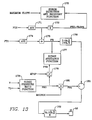
- the blowoff valve control loop 128 includes a data handling portion 145, a modulation portion 146, a surge avoidance portion 148, and a surge detection and recovery portion 149.
- the data handling portion 145 reads pressures PT0, PT1, and PT2 which are provided by the pressure sensors or transducers 9, 25, and 32, respectively.
- running averages of PT1 and PT2 are calculated for use in the pressure ratio calculation.
- An "averaging" section determines the rate of change in PT2, known as PT2-SLOPE, by using the latest four values of the running averages of PT2.
- the value of PT2-SLOPE is a running value, and it indicates to the controller 130 how quickly the pressure in the discharge port 30 is changing. This value is used to determine whether the slope of the pressure applied to PT2 is sufficiently steep to indicate a surge event.
- the modulation portion 146 as flowcharted in Figure 20, first calculates the actual compressor pressure ratio, PR, by dividing the value of absolute pressure measured by sensor 32 (PT2) by the value of absolute pressure measured by sensor 25 (PT1).
- PR the actual compressor pressure ratio
- the blowoff valve control loop 128 calculates the critical pressure ratio PR3 as a function of compressor corrected speed (see Figure 5).
- the critical pressure ratio, PR3 is the value of the compressor pressure ratio where compressor surge is expected to occur at a particular value of compressor corrected operating speed.
- a value of the target safe pressure ratio PR1 is calculated by multiplying the critical pressure ratio, PR3, by a multiplier known as MSURGE.
- MSURGE is a fractional number used to determine the margin away from actual surge condition that the compressor should ideally operate. For example, MSURGE may be initially set at 0.92 each time the controller 130 is powered on. After PR1 is calculated, a pressure ratio error is then calculated as the difference between PR and PR1. Controller 130 uses "proportional integral" or "PI" control techniques, provided by Figure 13, to minimize this error. This logic forces the blowoff valve 52 to close when actual pressure ratio, PR, is less than target pressure ratio, PR1. Conversely, the blowoff valve 52 is positioned further open when the actual pressure ratio, PR, is greater than the target pressure ratio, PR1.
- the average pressures are calculated by the averaging functions 171 and 174.
- the slope with respect to time of the average value of PT2 is calculated with the differential function 172. This slope is compared to a specified setpoint MAXSLOPE in the surge detection and recovery function, 173.
- the pressure ratio is calculated by the division function 175 and then processed by the lead-lag integrator 176.
- the target pressure ratio is determined by first calculating PR3 with the surge pressure ratio function 179, and then multiplying by MSURGE in function 180.
- the control error is calculated by the SUM function 181 and the output signal to the blowoff valve 52 is calculated in the P-I control function 182.
- the maximum safe pressure ratio, PR2 is calculated by the multiply function 178, and is compared to the actual ratio, PR, in the surge avoidance function 177.
- the surge avoidance portion 148 permits a quick reset of the blowoff valve 52 to a more open position if the actual compressor pressure ratio rises above the target value and reaches the maximum safe operating pressure ratio, as explained in further detail hereinafter.
- the controller 130 compares the actual pressure ratio, PR, to the maximum safe operating compressor pressure ratio, PR2, which is calculated by multiplying the critical pressure ratio, PR3, by a multiplier known as MPOP.
- MPOP is a fractional number used to determine the pressure ratio at which the "PI" controls of the blowoff valve should stop to perform a quick reset on the blowoff valve 52 to quickly lower the actual pressure ratio below PR2. This technique of quickly resetting or "popping" the blowoff value to a predetermined open position is a technique of surge prevention or avoidance.
- a final product of every pass through of the blowoff valve control loop 128 is a new position for the blowoff valve 52.
- the surge detection and recovery portion 149 is a method of detecting an actual surge event and reacting to the surge event so as to recover therefrom without unloading or shutting down the compressor.
- Section 149 of the blowoff valve loop 128 performs a surge check during each pass through the blowoff valve control loop 128.
- the controller 130 calculates the slope with respect to time of the actual compressor discharge pressure, PT2. If this slope, known as PT2-SLOPE, is more negative i.e., a downward spike, than a particular predetermined value, the controller initiates a surge recovery action known as "surge reset". In a surge reset, the controller 130 quickly adjusts the value of the blowoff valve position to a predetermined open position so as to relieve the high pressure ratio condition. Once done, the blowoff valve loop 128 resumes normal "PI" control or modulation of the blowoff valve 52 so as to achieve the response to a surge shown in Figure 12. Simultaneous with the surge reset action, the controller 130 decrements MSURGE in order to avoid yet a second surge condition. Any time that a surge reset occurs, the logic provides that a specified amount of time must expire before repeating the surge reset action. This time period gives the modulation portion 146 time to regain control of the compressor without being interrupted by subsequent resets.
- PT2-SLOPE a surge recovery action
- the controller 130 sets a software flag indicating that a probable surge is occurring. On subsequent scans for a predetermined time period, e.g., 2 seconds, the controller 130 checks for a following upward spike in compressor discharge pressure that exceeds a particular predetermined value. If found, the controller 130 proclaims that a definite surge has occurred. If a predetermined number of surges occurs within a predetermined time period, the controller 130 causes the compressor to shut down.
- a predetermined time period e.g. 2 seconds
- the type of output signal from the blowoff valve loop 128 to the blowoff valve 52 varies with the type of blowoff valve positioning device used.
- it may consist of an analog current signal varying between 4 and 20 milliamps used as an input signal to an electro-pneumatic valve positioning system employing a current-to-pressure transducer and a pneumatic valve positioner/actuator system.
- the output may consist of a variable frequency signal used to drive a stepper motor driver on a butterfly valve unit.
- the exact type of blowoff valve positioning device is independent of this embodiment.
Landscapes
- Engineering & Computer Science (AREA)
- Mechanical Engineering (AREA)
- General Engineering & Computer Science (AREA)
- Life Sciences & Earth Sciences (AREA)
- Sustainable Development (AREA)
- Control Of Positive-Displacement Air Blowers (AREA)
Priority Applications (3)
| Application Number | Priority Date | Filing Date | Title |
|---|---|---|---|
| EP96107567A EP0732509A3 (en) | 1992-04-10 | 1993-04-08 | Apparatus for detecting and preventing fluid surge in a centrifugal compressor |
| EP96107566A EP0732508A3 (en) | 1992-04-10 | 1993-04-08 | Method and apparatus for detecting and preventing fluid surge in a centrifugal compressor |
| EP96107565A EP0732507A3 (en) | 1992-04-10 | 1993-04-08 | Method and apparatus for detecting and preventing fluid surge in a centrifugal compressor |
Applications Claiming Priority (4)
| Application Number | Priority Date | Filing Date | Title |
|---|---|---|---|
| US86730492A | 1992-04-10 | 1992-04-10 | |
| US867304 | 1992-04-10 | ||
| US08/029,195 US5306116A (en) | 1992-04-10 | 1993-03-10 | Surge control and recovery for a centrifugal compressor |
| US29195 | 1993-03-10 |
Related Child Applications (6)
| Application Number | Title | Priority Date | Filing Date |
|---|---|---|---|
| EP96107567.8 Division-Into | 1993-04-08 | ||
| EP96107567A Division EP0732509A3 (en) | 1992-04-10 | 1993-04-08 | Apparatus for detecting and preventing fluid surge in a centrifugal compressor |
| EP96107565.2 Division-Into | 1993-04-08 | ||
| EP96107565A Division EP0732507A3 (en) | 1992-04-10 | 1993-04-08 | Method and apparatus for detecting and preventing fluid surge in a centrifugal compressor |
| EP96107566.0 Division-Into | 1993-04-08 | ||
| EP96107566A Division EP0732508A3 (en) | 1992-04-10 | 1993-04-08 | Method and apparatus for detecting and preventing fluid surge in a centrifugal compressor |
Publications (3)
| Publication Number | Publication Date |
|---|---|
| EP0565373A2 EP0565373A2 (en) | 1993-10-13 |
| EP0565373A3 EP0565373A3 (OSRAM) | 1994-01-19 |
| EP0565373B1 true EP0565373B1 (en) | 1996-11-20 |
Family
ID=26704656
Family Applications (4)
| Application Number | Title | Priority Date | Filing Date |
|---|---|---|---|
| EP93302766A Expired - Lifetime EP0565373B1 (en) | 1992-04-10 | 1993-04-08 | Method and apparatus for detecting and preventing fluid surge in a centrifugal compressor |
| EP96107567A Withdrawn EP0732509A3 (en) | 1992-04-10 | 1993-04-08 | Apparatus for detecting and preventing fluid surge in a centrifugal compressor |
| EP96107566A Withdrawn EP0732508A3 (en) | 1992-04-10 | 1993-04-08 | Method and apparatus for detecting and preventing fluid surge in a centrifugal compressor |
| EP96107565A Withdrawn EP0732507A3 (en) | 1992-04-10 | 1993-04-08 | Method and apparatus for detecting and preventing fluid surge in a centrifugal compressor |
Family Applications After (3)
| Application Number | Title | Priority Date | Filing Date |
|---|---|---|---|
| EP96107567A Withdrawn EP0732509A3 (en) | 1992-04-10 | 1993-04-08 | Apparatus for detecting and preventing fluid surge in a centrifugal compressor |
| EP96107566A Withdrawn EP0732508A3 (en) | 1992-04-10 | 1993-04-08 | Method and apparatus for detecting and preventing fluid surge in a centrifugal compressor |
| EP96107565A Withdrawn EP0732507A3 (en) | 1992-04-10 | 1993-04-08 | Method and apparatus for detecting and preventing fluid surge in a centrifugal compressor |
Country Status (4)
| Country | Link |
|---|---|
| US (1) | US5306116A (OSRAM) |
| EP (4) | EP0565373B1 (OSRAM) |
| JP (1) | JPH0610885A (OSRAM) |
| DE (1) | DE69306026T2 (OSRAM) |
Cited By (1)
| Publication number | Priority date | Publication date | Assignee | Title |
|---|---|---|---|---|
| US9568894B2 (en) | 2007-06-12 | 2017-02-14 | Ford Global Technologies, Llc | Method and control system for a compressor that is operable with a climate system |
Families Citing this family (83)
| Publication number | Priority date | Publication date | Assignee | Title |
|---|---|---|---|---|
| US5386873A (en) * | 1993-06-09 | 1995-02-07 | Ingersoll-Rand Company | Cooling system for engine-driven multi-stage centrifugal compressor |
| US5443369A (en) * | 1993-06-09 | 1995-08-22 | Ingersoll-Rand Company | Self-contained instrument and seal air system for a centrifugal compressor |
| US5508943A (en) * | 1994-04-07 | 1996-04-16 | Compressor Controls Corporation | Method and apparatus for measuring the distance of a turbocompressor's operating point to the surge limit interface |
| FI104205B1 (fi) * | 1994-11-24 | 1999-11-30 | Sarlin Hydor Oy | Menetelmä ja laitteisto virtaavan väliaineen kompressointijärjestelmän ohjaamiseksi |
| US5743715A (en) * | 1995-10-20 | 1998-04-28 | Compressor Controls Corporation | Method and apparatus for load balancing among multiple compressors |
| US5709526A (en) * | 1996-01-02 | 1998-01-20 | Woodward Governor Company | Surge recurrence prevention control system for dynamic compressors |
| DE69727044T2 (de) * | 1996-01-02 | 2004-10-14 | Woodward Governor Co., Loveland | Regelsystem zur überspannungsverhütung bei dynamischen kompressoren |
| DE69708319T2 (de) | 1996-05-22 | 2002-08-22 | Ingersoll-Rand Co., Woodcliff Lake | Erkennungsverfahren für druckstoss in turboverdichter |
| US5908462A (en) * | 1996-12-06 | 1999-06-01 | Compressor Controls Corporation | Method and apparatus for antisurge control of turbocompressors having surge limit lines with small slopes |
| US6141951A (en) * | 1998-08-18 | 2000-11-07 | United Technologies Corporation | Control system for modulating bleed in response to engine usage |
| IT1302949B1 (it) * | 1998-12-28 | 2000-10-10 | Giovambattista Greco | Motore endotermico a combustione interna con propulsione reattiva emoto "circolare". |
| EP1069314A1 (de) * | 1999-07-16 | 2001-01-17 | Abb Research Ltd. | Regelung einer Kompressoreinheit |
| DE10012380A1 (de) * | 2000-03-14 | 2001-09-20 | Man Turbomasch Ag Ghh Borsig | Verfahren zum Schutz eines Turbokompressors vor Betrieb im instabilen Arbeitsbereich |
| JP3837278B2 (ja) * | 2000-08-10 | 2006-10-25 | 株式会社神戸製鋼所 | 圧縮機の運転方法 |
| NO313926B1 (no) * | 2000-11-08 | 2002-12-23 | Abb Research Ltd | Kompressorstyring |
| JP3751208B2 (ja) * | 2001-02-23 | 2006-03-01 | 株式会社神戸製鋼所 | 多段可変速圧縮機の制御方法 |
| US6981838B2 (en) | 2002-02-26 | 2006-01-03 | Southern Gas Association Gas Machinery Reserach Council | Method and apparatus for detecting the occurrence of surge in a centrifugal compressor |
| US7752681B2 (en) | 2002-05-24 | 2010-07-13 | Michel Licensing, Inc. | Article of clothing with wicking portion |
| DE10252975A1 (de) * | 2002-11-14 | 2004-06-03 | Knorr-Bremse Systeme für Nutzfahrzeuge GmbH | Kompressoranordnung mit einer Zusatzverdichtereinheit, insbesondere für Nutzfahrzeuge |
| DE10256193A1 (de) | 2002-12-02 | 2004-06-09 | Alstom Technology Ltd | Verfahren zur Steuerung der Flüssigkeitseinspritzung in einen Zuströmkanal einer Kraft- oder Arbeitsmaschine |
| EP1616135B8 (en) * | 2003-04-17 | 2015-03-11 | Daikin Applied Americas Inc. | Methods for detecting surge in centrifugal compressors |
| US7094019B1 (en) * | 2004-05-17 | 2006-08-22 | Continuous Control Solutions, Inc. | System and method of surge limit control for turbo compressors |
| JP4496886B2 (ja) * | 2004-08-25 | 2010-07-07 | 株式会社日立プラントテクノロジー | ターボ圧縮機システムの運転方法 |
| EP1659294B1 (en) * | 2004-11-17 | 2017-01-11 | Mitsubishi Heavy Industries Compressor Corporation | Compressor control unit and gas turbine power plant including this unit |
| DE102004060206B3 (de) | 2004-12-14 | 2006-06-14 | Siemens Ag | Verfahren zum Betrieb eines stromrichtergespeisten Verdichters |
| US8826680B2 (en) * | 2005-12-28 | 2014-09-09 | Johnson Controls Technology Company | Pressure ratio unload logic for a compressor |
| EP1984628B1 (en) * | 2006-02-13 | 2014-12-17 | Ingersoll-Rand Company | Multi-stage compression system and method of operating the same |
| BE1017162A3 (nl) * | 2006-06-09 | 2008-03-04 | Atlas Copco Airpower Nv | Inrichting voor het regelen van de werkdruk van een oliege njecteerde compressorinstallatie. |
| US7712299B2 (en) * | 2006-09-05 | 2010-05-11 | Conocophillips Company | Anti-bogdown control system for turbine/compressor systems |
| US7963749B1 (en) | 2006-11-25 | 2011-06-21 | Climatecraft Technologies, Inc. | Fan with variable motor speed and disk type unloading device |
| US7854402B1 (en) * | 2007-10-02 | 2010-12-21 | Travis Tonny D | Hydraulic system valving |
| US8353175B2 (en) * | 2008-01-08 | 2013-01-15 | Calvin Wade Wohlert | Roof top air conditioning units having a centralized refrigeration system |
| DE102008005354B4 (de) * | 2008-01-21 | 2016-05-25 | Man Diesel & Turbo Se | Verfahren zur Regelung einer Strömungsmaschine |
| WO2009096938A1 (en) * | 2008-01-29 | 2009-08-06 | Cypress Systems Corporation, A Delaware Corporation | Pneumatic-to-digital devices, systems and methods |
| US20090297333A1 (en) * | 2008-05-28 | 2009-12-03 | Saul Mirsky | Enhanced Turbocompressor Startup |
| DE102008021102A1 (de) * | 2008-04-28 | 2009-10-29 | Siemens Aktiengesellschaft | Wirkungsgradüberwachung eines Verdichters |
| US8323000B2 (en) * | 2008-06-23 | 2012-12-04 | Compressor Controls Corp. | Compressor-driver power limiting in consideration of antisurge control |
| US8525361B1 (en) | 2008-10-06 | 2013-09-03 | Cypress Envirosystems, Inc. | Pneumatic energy harvesting devices, methods and systems |
| US8814639B1 (en) | 2008-10-29 | 2014-08-26 | Climatecraft Technologies, Inc. | Fan system comprising fan array with surge control |
| US8311684B2 (en) * | 2008-12-17 | 2012-11-13 | Pratt & Whitney Canada Corp. | Output flow control in load compressor |
| US8291720B2 (en) * | 2009-02-02 | 2012-10-23 | Optimum Energy, Llc | Sequencing of variable speed compressors in a chilled liquid cooling system for improved energy efficiency |
| US20120100013A9 (en) * | 2010-05-11 | 2012-04-26 | Krishnan Narayanan | Method of surge protection for a dynamic compressor using a surge parameter |
| US10900492B2 (en) | 2010-05-11 | 2021-01-26 | Energy Control Technologies, Inc. | Method of anti-surge protection for a dynamic compressor using a surge parameter |
| IT1401663B1 (it) * | 2010-08-31 | 2013-08-02 | Nuovo Pignone Spa | Dispositivo e metodo per rilevare una sovracorrente in un compressore e spostare un margine di sovracorrente. |
| IT1402481B1 (it) * | 2010-10-27 | 2013-09-13 | Nuovo Pignone Spa | Metodo e dispositivo che effettua una compensazione del tempo morto di anti-pompaggio basata su modello |
| US20110203269A1 (en) * | 2011-03-17 | 2011-08-25 | Ford Global Technologies, Llc | Engine Vacuum System |
| CN102182700B (zh) * | 2011-05-19 | 2013-08-21 | 哈尔滨工业大学 | 涡轮增压系统压气机风量分配控制的喘振保护方法及实现该方法的喘振保护装置 |
| US10436208B2 (en) * | 2011-06-27 | 2019-10-08 | Energy Control Technologies, Inc. | Surge estimator |
| US20130039781A1 (en) * | 2011-08-08 | 2013-02-14 | Victor Pascu | Anticipation logic for a surge control valve utilized with load compressor |
| JP5878737B2 (ja) | 2011-11-17 | 2016-03-08 | 株式会社神戸製鋼所 | 圧縮装置 |
| CN103946555B (zh) * | 2011-12-01 | 2016-09-07 | 开利公司 | 冷却装置压缩机的启动期间的喘振阻止 |
| US9885508B2 (en) | 2011-12-28 | 2018-02-06 | Carrier Corporation | Discharge pressure calculation from torque in an HVAC system |
| JP5611253B2 (ja) * | 2012-02-23 | 2014-10-22 | 三菱重工業株式会社 | 圧縮機制御装置及びその制御方法、圧縮機システム |
| US9702365B2 (en) | 2012-05-31 | 2017-07-11 | Praxair Technology, Inc. | Anti-surge speed control |
| JP6078300B2 (ja) * | 2012-11-07 | 2017-02-08 | カルソニックカンセイ株式会社 | 電動コンプレッサの制御装置 |
| ITFI20130064A1 (it) * | 2013-03-26 | 2014-09-27 | Nuovo Pignone Srl | "methods and systems for controlling turbocompressors" |
| US9436188B2 (en) * | 2013-05-24 | 2016-09-06 | GM Global Technology Operations LLC | Systems and methods for detecting compressor surge |
| US9695834B2 (en) * | 2013-11-25 | 2017-07-04 | Woodward, Inc. | Load sharing control for compressors in series |
| SE540370C2 (en) * | 2014-04-29 | 2018-08-21 | Scania Cv Ab | Förfarande samt system för styrning av ett överladdningssystem vid ett motorfordon |
| US9528913B2 (en) | 2014-07-24 | 2016-12-27 | General Electric Company | Method and systems for detection of compressor surge |
| US20160187893A1 (en) * | 2014-12-31 | 2016-06-30 | Ingersoll-Rand Company | System and method using parallel compressor units |
| US9780422B2 (en) | 2015-05-20 | 2017-10-03 | Ford Global Technologies, Llc | Cabin and battery cooling control for electrified vehicles |
| ITUB20152030A1 (it) * | 2015-07-09 | 2017-01-09 | Nuovo Pignone Tecnologie Srl | Sistema di compressore con una disposizione di raffreddamento tra la valvola di anti-pompaggio ed il lato di aspirazione del compressore, e relativo metodo |
| US9988153B2 (en) * | 2015-07-13 | 2018-06-05 | Hamilton Sundstrand Space Systems | RAF bit for surge detection |
| RU2016112469A (ru) * | 2016-04-01 | 2017-10-04 | Фишер-Роузмаунт Системз, Инк. | Способы и устройство для обнаружения и предотвращения помпажа компрессора |
| US10309297B2 (en) * | 2016-06-23 | 2019-06-04 | Ge Global Sourcing Llc | Method and systems for a turbocharger |
| US10989210B2 (en) | 2017-07-10 | 2021-04-27 | Praxair Technology, Inc. | Anti-surge speed control for two or more compressors |
| US10859097B2 (en) * | 2018-03-19 | 2020-12-08 | Garrett Transportation I Inc. | Method for controlling a trim-adjustment mechanism for a centrifugal compressor |
| EP3969758B1 (en) | 2019-05-14 | 2025-07-02 | Carrier Corporation | Method and system for compressor operating range extension via active valve control |
| FR3099806B1 (fr) * | 2019-08-07 | 2021-09-03 | Safran Power Units | Régulation anti-pompage d’un compresseur de charge équipant un groupe auxiliaire de puissance |
| KR102229398B1 (ko) * | 2019-10-31 | 2021-03-19 | 유진기공산업주식회사 | 압축기 시스템 및 이의 제어 방법 |
| US11644227B2 (en) * | 2020-09-01 | 2023-05-09 | Emerson Climate Technologies, Inc. | Start-stop control systems and methods for gas foil bearing machine |
| DE102021207396A1 (de) * | 2021-07-13 | 2023-01-19 | Robert Bosch Gesellschaft mit beschränkter Haftung | Verfahren zum Betreiben einer Strömungsmaschine sowie Steuergerät |
| CN114278602B (zh) * | 2022-01-05 | 2023-12-01 | 重庆江增船舶重工有限公司 | 一种蒸汽压缩机喘振与温度协调控制系统 |
| US12196470B2 (en) | 2022-05-27 | 2025-01-14 | Copeland Lp | Systems and methods for determining startup pressure ratio for dynamic compressors |
| CN115324921B (zh) * | 2022-07-27 | 2025-08-19 | 东风汽车集团股份有限公司 | 一种空压机喘振判定方法、装置及设备 |
| CN115419831B (zh) * | 2022-08-10 | 2024-09-10 | 中国石油化工股份有限公司 | 一种降低低压氮压机蒸汽消耗的装置 |
| CN116357623B (zh) * | 2023-03-14 | 2023-11-24 | 深圳市氢蓝时代动力科技有限公司 | 一种燃料电池用离心式空压机防喘振控制方法 |
| CN116498591A (zh) * | 2023-05-23 | 2023-07-28 | 成都成发科能动力工程有限公司 | 一种轴流压缩机喘振实验自动测试方法 |
| CN117108540B (zh) * | 2023-10-12 | 2023-12-19 | 山东天瑞重工有限公司 | 磁悬浮鼓风机的防喘振保压控制方法及系统 |
| EP4542039A1 (de) * | 2023-10-20 | 2025-04-23 | Burckhardt Compression AG | Verfahren zur steuerung eines kompressorsystems |
| US20250137458A1 (en) * | 2023-10-27 | 2025-05-01 | Garrett Transportation I Inc. | Multi-stage electric compressor energy consumption optimization |
| CN120740242B (zh) * | 2025-08-25 | 2025-10-28 | 亚之捷智能装备(江苏)有限公司 | 一种热泵系统控制保护方法 |
Family Cites Families (38)
| Publication number | Priority date | Publication date | Assignee | Title |
|---|---|---|---|---|
| DE1107887B (de) * | 1957-04-16 | 1961-05-31 | Power Jets Res & Dev Ltd | Regler zur Pumpverhuetung bei Stroemungsverdichtern |
| CH432080A (de) * | 1965-12-22 | 1967-03-15 | Bbc Brown Boveri & Cie | Regler mit nachgiebiger Rückführung |
| CH533243A (de) * | 1971-08-04 | 1973-01-31 | Mitsui Shipbuilding Eng | Verfahren zur Regelung einer Kompressoranlage sowie Kompressoranlage zur Ausführung des Verfahrens |
| US4164033A (en) * | 1977-09-14 | 1979-08-07 | Sundstrand Corporation | Compressor surge control with airflow measurement |
| US4164035A (en) * | 1977-09-14 | 1979-08-07 | Sundstrand Corporation | Surge control for variable speed-variable geometry compressors |
| JPS5535173A (en) * | 1978-09-02 | 1980-03-12 | Kobe Steel Ltd | Method of and apparatus for enlarging surge margin in centrifugal compressor and axial flow conpressor |
| DE3105376C2 (de) * | 1981-02-14 | 1984-08-23 | M.A.N. Maschinenfabrik Augsburg-Nürnberg AG, 4200 Oberhausen | Verfahren zum Betreiben von Turboverdichtern |
| US4464720A (en) * | 1982-02-12 | 1984-08-07 | The Babcock & Wilcox Company | Centrifugal compressor surge control system |
| US4462561A (en) * | 1982-05-27 | 1984-07-31 | Lockheed Corporation | Energy efficient ECS powered by a variable voltage/variable frequency power system |
| US4640665A (en) * | 1982-09-15 | 1987-02-03 | Compressor Controls Corp. | Method for controlling a multicompressor station |
| US4834622A (en) * | 1983-06-15 | 1989-05-30 | Sundstrand Corporation | Gas turbine engine/load compressor power plants |
| US4560319A (en) * | 1983-08-01 | 1985-12-24 | MAN Maschinenfabrik Unternehmensbereich GHH Sterkrade | Method and apparatus for controlling at least two parallel-connected turbocompressors |
| DE3582821D1 (de) * | 1984-05-14 | 1991-06-20 | Dresser Ind | System, einrichtung und verfahren zur erkennung und regelung des pumpens in einem turboverdichter. |
| US4791569A (en) * | 1985-03-18 | 1988-12-13 | Honda Giken Kogyo Kabushiki Kaisha | Electronic control system for internal combustion engines |
| US4646534A (en) * | 1985-07-15 | 1987-03-03 | Earl Russell | Means for refrigeration speed control |
| DE3540088A1 (de) * | 1985-11-12 | 1987-05-14 | Gutehoffnungshuette Man | Verfahren zur erfassung von pumpstoessen an turbokompressoren |
| DE3540285A1 (de) * | 1985-11-13 | 1987-05-14 | Gutehoffnungshuette Man | Verfahren und einrichtung zum regeln von turbokompressoren |
| DE3540284A1 (de) * | 1985-11-13 | 1987-05-14 | Gutehoffnungshuette Man | Einrichtung zum regeln eines turbokompressors zur verhinderung des pumpens |
| DE3544822A1 (de) * | 1985-12-18 | 1987-06-19 | Gutehoffnungshuette Man | Verfahren zur pumpgrenzregelung von turbokomporessoren |
| DE3544821A1 (de) * | 1985-12-18 | 1987-06-19 | Gutehoffnungshuette Man | Verfahren zum regeln von turbokompressoren zur vermeidung des pumpens |
| JP2619360B2 (ja) * | 1986-02-21 | 1997-06-11 | 株式会社日立製作所 | ターボ圧縮機のサージング防止装置 |
| DE3611553C1 (de) * | 1986-04-07 | 1987-07-23 | Orenstein & Koppel Ag | Anordnung zum Betrieb eines dieselhydraulischen Antriebes |
| US4807150A (en) * | 1986-10-02 | 1989-02-21 | Phillips Petroleum Company | Constraint control for a compressor system |
| US4781524A (en) * | 1987-02-12 | 1988-11-01 | Man Gutehoffnungshuette Gmbh | Method and apparatus for detecting pressure surges in a turbo-compressor |
| JPH01200095A (ja) * | 1988-02-03 | 1989-08-11 | Kobe Steel Ltd | 遠心圧縮機の制御方法 |
| DE3805119A1 (de) * | 1988-02-18 | 1989-08-31 | Gutehoffnungshuette Man | Verfahren und einrichtung zum regeln von turbokompressoren |
| DE3809070A1 (de) * | 1988-03-18 | 1989-10-26 | Gutehoffnungshuette Man | Verfahren zum sicheren betreiben von turbo-kompressoren |
| DE3809881A1 (de) * | 1988-03-24 | 1989-10-12 | Gutehoffnungshuette Man | Regelverfahren zur vermeidung des pumpens eines turbokompressors |
| DE3810717A1 (de) * | 1988-03-30 | 1989-10-19 | Gutehoffnungshuette Man | Verfahren zur vermeidung des pumpens eines turboverdichters mittels abblaseregelung |
| DE3811230A1 (de) * | 1988-04-02 | 1989-10-26 | Gutehoffnungshuette Man | Verfahren zum schuetzen eines turboverdichters vor pumpen mittels abblasens ueber ein abblaseventil sowie vorrichtung zur durchfuehrung des verfahrens |
| DE3811232A1 (de) * | 1988-04-02 | 1989-10-26 | Gutehoffnungshuette Man | Regelverfahren zum vermeiden des pumpens eines turboverdichters mittels bedarfsweisen abblasens |
| US5002459A (en) * | 1988-07-28 | 1991-03-26 | Rotoflow Corporation | Surge control system |
| US4949276A (en) * | 1988-10-26 | 1990-08-14 | Compressor Controls Corp. | Method and apparatus for preventing surge in a dynamic compressor |
| US4975024A (en) * | 1989-05-15 | 1990-12-04 | Elliott Turbomachinery Co., Inc. | Compressor control system to improve turndown and reduce incidents of surging |
| US5095714A (en) * | 1989-12-25 | 1992-03-17 | Daikin Industries, Ltd. | Surging prediction device for a centrifugal compressor |
| US5046928A (en) * | 1989-12-26 | 1991-09-10 | Westingshouse Electric Corp. | Long term compressor control apparatus |
| US5032062A (en) * | 1989-12-26 | 1991-07-16 | Westinghouse Electric Corp. | Compressor demand control system for long term compressor operation |
| US5019757A (en) * | 1990-03-19 | 1991-05-28 | General Electric Company | Method and apparatus for controlling a blower motor in an air handling system to provide constant pressure |
-
1993
- 1993-03-10 US US08/029,195 patent/US5306116A/en not_active Expired - Fee Related
- 1993-04-08 EP EP93302766A patent/EP0565373B1/en not_active Expired - Lifetime
- 1993-04-08 EP EP96107567A patent/EP0732509A3/en not_active Withdrawn
- 1993-04-08 DE DE69306026T patent/DE69306026T2/de not_active Expired - Fee Related
- 1993-04-08 EP EP96107566A patent/EP0732508A3/en not_active Withdrawn
- 1993-04-08 EP EP96107565A patent/EP0732507A3/en not_active Withdrawn
- 1993-04-09 JP JP5082914A patent/JPH0610885A/ja active Pending
Cited By (1)
| Publication number | Priority date | Publication date | Assignee | Title |
|---|---|---|---|---|
| US9568894B2 (en) | 2007-06-12 | 2017-02-14 | Ford Global Technologies, Llc | Method and control system for a compressor that is operable with a climate system |
Also Published As
| Publication number | Publication date |
|---|---|
| EP0732507A2 (en) | 1996-09-18 |
| DE69306026D1 (de) | 1997-01-02 |
| US5306116A (en) | 1994-04-26 |
| EP0732507A3 (en) | 1998-07-08 |
| EP0732509A2 (en) | 1996-09-18 |
| EP0732509A3 (en) | 1998-07-08 |
| EP0732508A2 (en) | 1996-09-18 |
| EP0732508A3 (en) | 1998-07-22 |
| JPH0610885A (ja) | 1994-01-21 |
| DE69306026T2 (de) | 1997-05-28 |
| EP0565373A3 (OSRAM) | 1994-01-19 |
| EP0565373A2 (en) | 1993-10-13 |
Similar Documents
| Publication | Publication Date | Title |
|---|---|---|
| EP0565373B1 (en) | Method and apparatus for detecting and preventing fluid surge in a centrifugal compressor | |
| EP0907910B1 (en) | Variable speed control of a centrifugal chiller using fuzzy logic | |
| JP2591898B2 (ja) | 圧縮機の主駆動機の制御装置及び制御方法 | |
| KR100381464B1 (ko) | 가변각흐름안내장치를구비한터보기계 | |
| JP2997319B2 (ja) | 圧縮機の非対称エアフローを用いたストール及びサージ制御 | |
| RU2454570C2 (ru) | Усовершенствования в регулировании компрессоров | |
| AU2007347705B2 (en) | Anti-bogdown control system for turbine/compressor systems | |
| KR100688854B1 (ko) | 팬회전속도 제어방법 | |
| US5222356A (en) | Modulating surge prevention control for a variable geometry diffuser | |
| US4164035A (en) | Surge control for variable speed-variable geometry compressors | |
| US4405290A (en) | Pneumatic supply system having variable geometry compressor | |
| US4255089A (en) | Method of controlling series fans driving a variable load | |
| EP0652374B1 (en) | System for controlling operation of turbo type fluid machinery | |
| US4662817A (en) | Apparatus and methods for preventing compressor surge | |
| EP0268545B1 (en) | Method and means for enhancing recovery of a surge condition in a gas turbine engine | |
| US4768338A (en) | Means for enhancing recovery of a surge condition in a gas turbine engine | |
| USRE31835E (en) | Pneumatic supply system having variable geometry compressor | |
| JP3384894B2 (ja) | ターボ圧縮機の容量制御方法 | |
| JPH06147190A (ja) | タンデム形遠心圧縮機装置 | |
| JP2977406B2 (ja) | 圧縮機の制御装置 | |
| JP2948421B2 (ja) | 圧縮機の制御装置 | |
| JPH0634195U (ja) | ターボ圧縮機のサージ防止制御装置 | |
| HOROWITZ et al. | 8.15 Compressor Control and Optimization |
Legal Events
| Date | Code | Title | Description |
|---|---|---|---|
| PUAI | Public reference made under article 153(3) epc to a published international application that has entered the european phase |
Free format text: ORIGINAL CODE: 0009012 |
|
| AK | Designated contracting states |
Kind code of ref document: A2 Designated state(s): DE FR GB IT NL |
|
| PUAL | Search report despatched |
Free format text: ORIGINAL CODE: 0009013 |
|
| AK | Designated contracting states |
Kind code of ref document: A3 Designated state(s): DE FR GB IT NL |
|
| 17P | Request for examination filed |
Effective date: 19940506 |
|
| 17Q | First examination report despatched |
Effective date: 19950425 |
|
| GRAG | Despatch of communication of intention to grant |
Free format text: ORIGINAL CODE: EPIDOS AGRA |
|
| GRAH | Despatch of communication of intention to grant a patent |
Free format text: ORIGINAL CODE: EPIDOS IGRA |
|
| GRAH | Despatch of communication of intention to grant a patent |
Free format text: ORIGINAL CODE: EPIDOS IGRA |
|
| GRAA | (expected) grant |
Free format text: ORIGINAL CODE: 0009210 |
|
| AK | Designated contracting states |
Kind code of ref document: B1 Designated state(s): DE FR GB IT NL |
|
| DX | Miscellaneous (deleted) | ||
| ITF | It: translation for a ep patent filed | ||
| REF | Corresponds to: |
Ref document number: 69306026 Country of ref document: DE Date of ref document: 19970102 |
|
| ET | Fr: translation filed | ||
| PLBE | No opposition filed within time limit |
Free format text: ORIGINAL CODE: 0009261 |
|
| STAA | Information on the status of an ep patent application or granted ep patent |
Free format text: STATUS: NO OPPOSITION FILED WITHIN TIME LIMIT |
|
| 26N | No opposition filed | ||
| REG | Reference to a national code |
Ref country code: GB Ref legal event code: IF02 |
|
| PGFP | Annual fee paid to national office [announced via postgrant information from national office to epo] |
Ref country code: FR Payment date: 20020319 Year of fee payment: 10 |
|
| PGFP | Annual fee paid to national office [announced via postgrant information from national office to epo] |
Ref country code: NL Payment date: 20020321 Year of fee payment: 10 |
|
| PGFP | Annual fee paid to national office [announced via postgrant information from national office to epo] |
Ref country code: GB Payment date: 20020403 Year of fee payment: 10 |
|
| PGFP | Annual fee paid to national office [announced via postgrant information from national office to epo] |
Ref country code: DE Payment date: 20020418 Year of fee payment: 10 |
|
| PG25 | Lapsed in a contracting state [announced via postgrant information from national office to epo] |
Ref country code: GB Free format text: LAPSE BECAUSE OF NON-PAYMENT OF DUE FEES Effective date: 20030408 |
|
| PG25 | Lapsed in a contracting state [announced via postgrant information from national office to epo] |
Ref country code: NL Free format text: LAPSE BECAUSE OF NON-PAYMENT OF DUE FEES Effective date: 20031101 Ref country code: DE Free format text: LAPSE BECAUSE OF NON-PAYMENT OF DUE FEES Effective date: 20031101 |
|
| GBPC | Gb: european patent ceased through non-payment of renewal fee |
Effective date: 20030408 |
|
| NLV4 | Nl: lapsed or anulled due to non-payment of the annual fee |
Effective date: 20031101 |
|
| PG25 | Lapsed in a contracting state [announced via postgrant information from national office to epo] |
Ref country code: FR Free format text: LAPSE BECAUSE OF NON-PAYMENT OF DUE FEES Effective date: 20031231 |
|
| REG | Reference to a national code |
Ref country code: FR Ref legal event code: ST |
|
| PG25 | Lapsed in a contracting state [announced via postgrant information from national office to epo] |
Ref country code: IT Free format text: LAPSE BECAUSE OF NON-PAYMENT OF DUE FEES;WARNING: LAPSES OF ITALIAN PATENTS WITH EFFECTIVE DATE BEFORE 2007 MAY HAVE OCCURRED AT ANY TIME BEFORE 2007. THE CORRECT EFFECTIVE DATE MAY BE DIFFERENT FROM THE ONE RECORDED. Effective date: 20050408 |