EP0564896A1 - Poldurchführung für Akkumulatorenzellen - Google Patents
Poldurchführung für Akkumulatorenzellen Download PDFInfo
- Publication number
- EP0564896A1 EP0564896A1 EP93104811A EP93104811A EP0564896A1 EP 0564896 A1 EP0564896 A1 EP 0564896A1 EP 93104811 A EP93104811 A EP 93104811A EP 93104811 A EP93104811 A EP 93104811A EP 0564896 A1 EP0564896 A1 EP 0564896A1
- Authority
- EP
- European Patent Office
- Prior art keywords
- pole
- flange
- cover
- pole socket
- ribs
- Prior art date
- Legal status (The legal status is an assumption and is not a legal conclusion. Google has not performed a legal analysis and makes no representation as to the accuracy of the status listed.)
- Granted
Links
Images
Classifications
-
- H—ELECTRICITY
- H01—ELECTRIC ELEMENTS
- H01M—PROCESSES OR MEANS, e.g. BATTERIES, FOR THE DIRECT CONVERSION OF CHEMICAL ENERGY INTO ELECTRICAL ENERGY
- H01M50/00—Constructional details or processes of manufacture of the non-active parts of electrochemical cells other than fuel cells, e.g. hybrid cells
- H01M50/10—Primary casings; Jackets or wrappings
- H01M50/172—Arrangements of electric connectors penetrating the casing
-
- H—ELECTRICITY
- H01—ELECTRIC ELEMENTS
- H01M—PROCESSES OR MEANS, e.g. BATTERIES, FOR THE DIRECT CONVERSION OF CHEMICAL ENERGY INTO ELECTRICAL ENERGY
- H01M50/00—Constructional details or processes of manufacture of the non-active parts of electrochemical cells other than fuel cells, e.g. hybrid cells
-
- H—ELECTRICITY
- H01—ELECTRIC ELEMENTS
- H01M—PROCESSES OR MEANS, e.g. BATTERIES, FOR THE DIRECT CONVERSION OF CHEMICAL ENERGY INTO ELECTRICAL ENERGY
- H01M50/00—Constructional details or processes of manufacture of the non-active parts of electrochemical cells other than fuel cells, e.g. hybrid cells
- H01M50/50—Current conducting connections for cells or batteries
- H01M50/543—Terminals
- H01M50/552—Terminals characterised by their shape
- H01M50/561—Hollow metallic terminals, e.g. terminal bushings
-
- Y—GENERAL TAGGING OF NEW TECHNOLOGICAL DEVELOPMENTS; GENERAL TAGGING OF CROSS-SECTIONAL TECHNOLOGIES SPANNING OVER SEVERAL SECTIONS OF THE IPC; TECHNICAL SUBJECTS COVERED BY FORMER USPC CROSS-REFERENCE ART COLLECTIONS [XRACs] AND DIGESTS
- Y02—TECHNOLOGIES OR APPLICATIONS FOR MITIGATION OR ADAPTATION AGAINST CLIMATE CHANGE
- Y02E—REDUCTION OF GREENHOUSE GAS [GHG] EMISSIONS, RELATED TO ENERGY GENERATION, TRANSMISSION OR DISTRIBUTION
- Y02E60/00—Enabling technologies; Technologies with a potential or indirect contribution to GHG emissions mitigation
- Y02E60/10—Energy storage using batteries
-
- Y—GENERAL TAGGING OF NEW TECHNOLOGICAL DEVELOPMENTS; GENERAL TAGGING OF CROSS-SECTIONAL TECHNOLOGIES SPANNING OVER SEVERAL SECTIONS OF THE IPC; TECHNICAL SUBJECTS COVERED BY FORMER USPC CROSS-REFERENCE ART COLLECTIONS [XRACs] AND DIGESTS
- Y02—TECHNOLOGIES OR APPLICATIONS FOR MITIGATION OR ADAPTATION AGAINST CLIMATE CHANGE
- Y02P—CLIMATE CHANGE MITIGATION TECHNOLOGIES IN THE PRODUCTION OR PROCESSING OF GOODS
- Y02P70/00—Climate change mitigation technologies in the production process for final industrial or consumer products
- Y02P70/50—Manufacturing or production processes characterised by the final manufactured product
Definitions
- the invention relates to a pole implementation through the lid of an accumulator cell.
- the poles of the accumulator cells which are led through the cover of the cell housing to the outside, must be sealed electrolytically against the cover, so that, for example in lead acid batteries, the very capillary-active sulfuric acid cannot escape to the outside. Due to the capillary active properties of sulfuric acid the ability to crawl through the finest cracks and cracks.
- Sockets are used for the passage of the electrical poles of a cell through the cell cover, which are injected when the cell cover made of plastic is injected.
- the electrical poles are then used later in the final assembly of the cells in the pole sockets. Accordingly, a distinction must be made between 1) the sealing of the pole socket against the cell cover and 2) the sealing of the electrical pole against the pole socket.
- the invention relates exclusively to the area of the electrolyte-tight seal between the pole socket and the cover of the battery cell.
- pole sockets have therefore become established in the past few years, which have, in their foot region, annularly surrounding, radially outwardly extending ribs, which form a so-called labyrinth, which is produced during the manufacture of the cover Plastic is molded into the lid.
- One problem relates to the formation of the ribs of the labyrinth on the outside at the foot area of the pole socket.
- the pole sockets are either cast from lead or cold-pressed from lead.
- a split mold must be used, the parting plane of which lies in the plane of the axis of the pole socket, since otherwise the ribs of the labyrinth projecting radially outward from the axis of the pole socket cannot be removed from the mold.
- the object of the invention is to look for a different and cheaper solution.
- the foot region of the pole socket has a flange which extends radially outward from the axis of the pole socket and that the ribs of the labyrinth extend from the flange approximately parallel to the axis of the pole socket.
- a second advantage results from the fact that the new design of the labyrinth requires a correspondingly different division level of the molding tool.
- the division plane must now be arranged so that the radially extending flange with the ribs extending parallel to the axis of the pole sleeve remains demoldable. Accordingly, the division plane is always to be chosen so that the flange lies in its radial extent fully in the division plane, so that the metallic burrs that can form in the division plane during casting or during compression molding of the pole socket always only on the outer diameter of the flange can arise and also only with a radial extension to the outside.
- the ridges which extend radially outward on the outer edge or the largest outer diameter of the flange are not disadvantageous for the tightness of the labyrinth. The opposite is the case. They have the effect of increasing the theoretical length of the labyrinth path that an electrolyte would have to travel from inside to outside on its way. This improves the effectiveness of the labyrinth seal. Accordingly, it can be accepted with the pole sockets according to the invention that metallic burrs are present on the outer circumference of the flange.
- a third advantage results from the fact that the labyrinth of the new pole socket for installation in the cell cover only requires a small installation height (measured in the axial direction of the pole socket). As a result, the foot region of the pole socket molded into the cell cover no longer protrudes so strongly into the interior of the battery cell. The interior of the rechargeable battery cells can thus be better used due to the higher electrode plates.
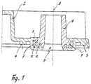
- the cell cover 2 shown in a partial section is made of plastic and, in the ready-to-use battery, its sealing surfaces 3 and 4 are placed tightly on a battery container (not shown). The distance between the sealing surfaces 3 and 3 corresponds to the width of a cell.
- the cell cover 2 projects only slightly downward into the interior of the cell with the foot region of the pole socket 6.
- the electrical pole (not shown) is used later in the final assembly of the cells in the inner cone 5 of the pole socket 6.
- a flange 7 which extends radially outwards.
- the molded-on ribs 9 and 10 are located on the underside and on the top of this flange 7. The ribs extend parallel to the axis 8 of the pole socket.
- the base region of the pole socket 6 is also inserted into the mold of the cover when the cover 2 is produced and, as can be seen from the illustration, is completely embedded in the material of the cell cover.
Landscapes
- Chemical & Material Sciences (AREA)
- Chemical Kinetics & Catalysis (AREA)
- Electrochemistry (AREA)
- General Chemical & Material Sciences (AREA)
- Sealing Battery Cases Or Jackets (AREA)
- Connection Of Batteries Or Terminals (AREA)
- External Artificial Organs (AREA)
- Micro-Organisms Or Cultivation Processes Thereof (AREA)
- Medicines That Contain Protein Lipid Enzymes And Other Medicines (AREA)
- Filling, Topping-Up Batteries (AREA)
Abstract
Description
- Die Erfindung betrifft eine Poldurchführung durch den Deckel einer Akkumulatorenzelle.
- Bekanntlich müssen die Pole der Akkumulatorenzellen, die durch den Deckel des Zellengehäuses nach außen hindurchgeführt sind, elektrolytdicht gegen den Deckel abgedichtet sein, damit z.B. bei Bleibatterien die sehr kapillaraktive Schwefelsäure nicht nach außen gelangen kann. Durch die kapillaraktiven Eigenschaften der Schwefelsäure hat diese die Fähigkeit, auch durch feinste Spalte und Haarrisse hindurchzukriechen.
- Für die Durchführung der elektrischen Pole einer Zelle durch den Zellendeckel werden Buchsen verwendet (sogenannte Polbuchsen), die beim Spritzen des aus Kunststoff bestehenden Zellendeckels mit eingespritzt werden. Die elektrischen Pole werden dann später bei der Endmontage der Zellen in die Polbuchsen eingesetzt. Dementsprechend ist zu unterscheiden zwischen 1) der Abdichtung der Polbuchse gegen den Zellendeckel und 2) der Abdichtung des elektrischen Pols gegen die Polbuchse. Die Erfindung betrifft aussschließlich den Bereich der elektrolytdichten Abdichtung zwischen Polbuchse und dem Deckel der Akkumulatorenzelle.
- Für diesen Bereich ist es bekannt, Gummidichtungen oder Vergußmassen auf der Basis eines Gießharzes, Schmelzklebers oder dergleichen zu verwenden, die jedoch relativ teuer sind und im Verlaufe der Gebrauchsdauer altern oder durch mechanische Einwirkungen undicht werden können.
- In der Praxis haben sich deshalb in den letzten Jahren Polbuchsen durchgesetzt, die in ihrem Fußbereich ringförmig umlaufende, radial nach außen sich erstreckende Rippen aufweisen, die ein sogenanntes Labyrinth bilden, das bei der Herstellung des Deckels aus Kunststoff in den Deckel mit eingeformt wird.
- Aber auch Labyrinth-Abdichtungen dieser Art sind mit erheblichen Problemen behaftet, wie dies in der erst kürzlich veröffentlichten US-PS 5 077 892 ausführlich beschrieben worden ist.
- Ein Problem betrifft das Anformen der Rippen des Labyrinths außenseitig am Fußbereich der Polbuchse. Bei den zur Zeit am meisten verbreiteten Bleibatterien werden die Polbuchsen entweder aus Blei gegossen oder aus Blei kalt formgepreßt. In beiden Fällen muß ein geteiltes Formwerkzeug verwendet werden, dessen Teilungsebene in der Ebene der Achse der Polbuchse liegt, da anders die von der Achse der Polbuchse radial nach außen vorstehenden Rippen des Labyrinths nicht entformbar sind.
- Diese Teilungsebene des Formwerkzeuges macht Schwierigkeiten, da dort die der Form entnommene Polbuchse immer einen mehr oder weniger stark ausgebildeten metallischen Grat aufweist. Wird dieser Grat nicht sorgfältig entfernt (was entsprechende Kosten verursacht), dann besteht die Gefahr, daß in diesem Bereich die Rippen des Labyrinths beim Spritzen des Kunststoffdeckels nicht ausreichend dicht von der Kunststoffmasse umflossen werden und Haarspalte in der Verbindung Polbuchse-Deckel vorhanden sein können, durch die Elektrolyt aus der Zelle austreten kann.
- In der bereits genannten US-PS 5 077 892 ist ein Weg beschrieben, die unerwünschte Gratausbildung an den Rippen des Labyrinths zu vermeiden. Dieser Weg erfordert zunächst die Herstellung eines homogenen Stangenmaterials aus Blei, das dann entsprechend der gewünschten Länge der Polbuchsen auf Länge geschnitten und sodann in einer Drehbank bearbeitet wird, um die ringförmig an der Außenseite der Polbuchse umlaufenden Rippen des Labyrinths gratfrei herzustellen. Das ist natürlich ein sehr aufwendiger Weg, der bei einer Großserienfertigung der Polbuchsen nicht wirtschaftlich ist.
- Aufgabe der Erfindung ist es, nach einem anderen und kostengünstigeren Lösungsweg zu suchen.
- Diese Aufgabe wird erfindungsgemäß nach Anspruch 1 dadurch gelöst, daß der Fußbereich der Polbuchse einen Flansch aufweist, der sich von der Achse der Polbuchse radial nach außen erstreckt und daß sich die Rippen des Labyrinths ausgehend von dem Flansch in etwa parallel zur Achse der Polbuchse erstrecken.
- Gemäß Anspruch 2 ist es vorteilhaft, den Flansch der Polbuchse sowohl an seiner Unterseite als auch an seiner Oberseite mit Rippen zu versehen.
- Durch die neue Ausbildung des Labyrinths mittels des Flansches und der davon ausgehenden Rippen werden wesentliche Vorteile erreicht.
- Zunächst ist ein Vorteil, daß auch die neue Ausbildung des Labyrinths durch Formguß oder Formpressen der Polbuchse hergestellt werden kann, wie dies bisher für die Großserienfertigung üblich und am kostengünstigsten ist.
- Ein zweiter Vorteil ergibt sich dadurch, daß die neue Ausbildung des Labyrinths eine entsprechend andere Teilungsebene des Formwerkzeuges erfordert. Die Teilungsebene muß jetzt so angeordnet sein, daß der radial sich erstreckende Flansch mit den parallel zur Achse der Polbuchse sich erstreckenden Rippen entformbar bleibt. Dementsprechend ist die Teilungsebene immer so zu wählen, daß der Flansch in seiner radialen Erstreckung voll in der Teilungsebene liegt, so daß die metallischen Grate, die sich beim Formguß oder beim Formpressen der Polbuchse in der Teilungsebene ausbilden können, immer nur am äußeren Durchmesser des Flansches entstehen können und zwar ebenfalls nur mit radialer Erstreckung nach außen.
- Gemäß Anspruch 3 ist es zweckmäßig, die Anordnung der Teilungsebene so zu wählen, daß sie die Achse der Polbuchse senkrecht schneidet und in Höhe des größten Außendurchmessers des Flansches angeordnet ist.
- Die sich am äußeren Rand bzw. am größten Außendurchmesser des Flansches radial nach außen erstreckenden Grate sind für die Dichtigkeit des Labyrinths nicht nachteilig. Das Gegenteil ist der Fall. Sie bewirken, daß die theoretische Länge des Labyrinthweges erhöht wird, den ein Elektrolyt auf seinem Wege von innen nach außen durchlaufen müßte. Dadurch ist die Wirksamtkeit der Labyrinth-Abdichtung verbessert. Dementsprechend kann bei den erfindungsgemäßen Polbuchsen akzeptiert werden, daß metallische Grate am äußeren Umfang des Flansches vorhanden sind.
- Ein dritter Vorteil ergibt sich dadurch, daß das Labyrinth der neuen Polbuchse für den Einbau in den Zellendeckel nur eine geringe Einbauhöhe (in Achsrichtung der Polbuchse gemessen) beansprucht. Dadurch steht der in den Zellendeckel eingeformte Fußbereich der Polbuchse nicht mehr so stark in den Innenraum der Akkumulatorenzelle vor. Der Innenraum der Akkumulatorenzellen kann somit durch höher gebaute Elektrodenplatten besser genutzt werden.
- Nachfolgend wird ein Ausführungsbeispiel der Erfindung anhand der Zeichnung näher beschrieben. Es zeigt:
- Fig. 1
- einen Querschnitt durch einen Zellendeckel mit Polbuchse.
- Der in einem Teilausschnitt dargestellte Zellendeckel 2 besteht aus Kunststoff und ist bei der gebrauchsfertigen Batterie mit seinen Dichtflächen 3 und 4 dicht auf ein Batteriegefäß (nicht dargestelt) aufgesetzt. Der Abstand der Dichtflächen 3 und 3 voneinander entspricht der Breite einer Zelle.
- Der Zellendeckel 2 steht mit dem Fußbereich der Polbuchse 6 nur geringfügig nach unten in den Innenraum der Zelle vor. Der elektrische Pol (nicht dargestellt) wird später bei der Endmontage der Zellen in den Innenkonus 5 der Polbuchse 6 eingesetzt.
- An dem Fußbereich der Polbuchse 6 ist ein Flansch 7 vorhanden, der sich radial nach außen erstreckt. An der Unterseite und an der Oberseite dieses Flansches 7 befinden sich die angeformten Rippen 9 und 10. Die Rippen erstrecken sich parallel zur Achse 8 der Polbuchse.
- Der Fußbereich der Polbuchse 6 wird bei der Herstellung des Deckels 2 in die Werkzeugform des Deckels mit eingelegt und ist - wie aus der Darstellung ersichtlich - vollständig in das Material des Zellendeckels eingebettet.
Claims (3)
- Elektrolytdichte Poldurchführung durch den Deckel einer Akkumulatorenzelle- mit einer Polbuchse, die in ihrem Fußbereich und außenseitig ringförmig umlaufende Rippen aufweist, die ein sogenanntes Labyrinth bilden, das bei der Herstellung des Deckels aus Kunststoff in den Deckel mit eingeformt wird,
dadurch gekennzeichnet,- daß der Fußbereich der Polbuchse (6) einen Flansch (7) aufweist, der sich von der Achse (8) der Polbuchse radial nach außen erstreckt- und daß sich die Rippen (9, 10) des Labyrinths ausgehend von dem Flansch (7) in etwa parallel zur Achse (8) der Polbuchse erstrecken. - Poldurchführung nach Anspruch 1,
dadurch gekennzeichnet,- daß der Flansch (7) sowohl an seiner Unterseite als auch an seiner Oberseite mit Rippen (9, 10) versehen ist. - Verfahren zur Herstellung der Poldurchführung nach Anspruch 1
dadurch gekennzeichnet,- daß die Teilungsebene des Formwerkzeuges zur Herstellung der Polbuchse (6) die Achse (8) der Polbuchse senkrecht schneidet- und in Höhe des größten Außendurchmessers des Flansches (7) angeordnet ist.
Applications Claiming Priority (2)
| Application Number | Priority Date | Filing Date | Title |
|---|---|---|---|
| DE4212214A DE4212214A1 (de) | 1992-04-08 | 1992-04-08 | Poldurchführung für Akkumulatorenzellen |
| DE4212214 | 1992-04-08 |
Publications (2)
| Publication Number | Publication Date |
|---|---|
| EP0564896A1 true EP0564896A1 (de) | 1993-10-13 |
| EP0564896B1 EP0564896B1 (de) | 1998-08-05 |
Family
ID=6456632
Family Applications (1)
| Application Number | Title | Priority Date | Filing Date |
|---|---|---|---|
| EP93104811A Expired - Lifetime EP0564896B1 (de) | 1992-04-08 | 1993-03-24 | Poldurchführung für Akkumulatorenzellen |
Country Status (6)
| Country | Link |
|---|---|
| US (1) | US5364714A (de) |
| EP (1) | EP0564896B1 (de) |
| JP (1) | JPH0689707A (de) |
| AT (1) | ATE169426T1 (de) |
| DE (2) | DE4212214A1 (de) |
| ZA (1) | ZA932487B (de) |
Cited By (1)
| Publication number | Priority date | Publication date | Assignee | Title |
|---|---|---|---|---|
| EP0836237A1 (de) * | 1996-10-09 | 1998-04-15 | Osvaldo Balbino Casais | Gratfreier korrosionsbeständiger Pol mit kurzer Verankerung für Speicherbatterien |
Families Citing this family (11)
| Publication number | Priority date | Publication date | Assignee | Title |
|---|---|---|---|---|
| IT239433Y1 (it) * | 1995-12-28 | 2001-02-26 | Stocchiero Olimpio | Elemento tubolare di tenuta per poli di accumulatori elettrici |
| ES2199631B1 (es) * | 2001-04-24 | 2005-05-16 | Bitron Industrie España, S.A. | Valvula electromagnetica para el control de fluidos. |
| US6644084B1 (en) * | 2001-06-14 | 2003-11-11 | Tulip Corporation | Method and apparatus for manufacturing a battery terminal with undercut rings |
| US7628049B2 (en) | 2001-06-14 | 2009-12-08 | Tulip Corporation | Method and apparatus for manufacturing a battery terminal with undercut rings |
| ITTO20020251A1 (it) * | 2002-03-20 | 2003-09-22 | I C S Ind Composizioni Stamp A | Terminale connettore per una batteria e batteria che lo comprende. |
| US7905384B1 (en) | 2002-06-04 | 2011-03-15 | Tulip Corporation | Cold formed battery terminal |
| US20060166081A1 (en) * | 2003-01-06 | 2006-07-27 | Tulip Corporation | Battery manifold vent |
| US7070441B1 (en) * | 2004-03-15 | 2006-07-04 | Tulip Corporation | Acid seal |
| DE202007003159U1 (de) * | 2007-03-01 | 2007-05-10 | Schunk Kohlenstofftechnik Gmbh | Kontaktstück |
| JP2012094372A (ja) * | 2010-10-27 | 2012-05-17 | Miyagawa Kasei Ind Co Ltd | 蓄電池の蓋、蓄電池の筐体および蓄電池 |
| JP6012102B2 (ja) * | 2012-10-26 | 2016-10-25 | 古河電池株式会社 | 鉛蓄電池用蓋 |
Citations (5)
| Publication number | Priority date | Publication date | Assignee | Title |
|---|---|---|---|---|
| US1411414A (en) * | 1919-04-07 | 1922-04-04 | Willard Storage Battery Co | Storage battery |
| DE1013339B (de) * | 1952-06-25 | 1957-08-08 | Trelleborgs Gummifabriks Ab | Poldurchfuehrung durch die Zellendeckel von Akkumulatoren, insbesondere von Bleiakkumulatoren |
| DE1146149B (de) * | 1959-02-26 | 1963-03-28 | Continental Gummi Werke Ag | Poldurchfuehrungsbuchse fuer elektrische Sammler |
| DE1953414A1 (de) * | 1968-10-25 | 1970-05-14 | Semperit Gummiwerk Gmbh Deutsc | Bleipol |
| DE1596128A1 (de) * | 1965-10-21 | 1971-04-01 | Globe Union Inc | Traeger fuer die Elektroden von Akkumulatoren |
Family Cites Families (10)
| Publication number | Priority date | Publication date | Assignee | Title |
|---|---|---|---|---|
| DE1671999B1 (de) * | 1967-11-11 | 1971-11-25 | Varta Ag | Poldurchfuehrung in form einer bleibuchse mit einem oder mehreren labyrinthringen |
| FR2140836A6 (de) * | 1971-04-08 | 1973-01-19 | Fulmen | |
| GB1415517A (en) * | 1972-02-29 | 1975-11-26 | Lucas Batteries Ltd | Electrical storage batteries |
| JPS59694Y2 (ja) * | 1978-06-27 | 1984-01-10 | 宮川化成工業株式会社 | 蓄電池 |
| SU754530A1 (ru) * | 1978-08-21 | 1980-08-07 | Nikolaj A Kononov | Устройство для пайки выводных клемм аккумуляторных батарей |
| US4389471A (en) * | 1978-12-16 | 1983-06-21 | Lucas Industries Limited | Electric storage batteries |
| SE7908222L (sv) * | 1979-10-04 | 1981-04-05 | Tudor Ab | Polgenomforing |
| SU892530A1 (ru) * | 1980-04-15 | 1981-12-23 | Предприятие П/Я Г-4036 | Устройство дл пайки выводов аккумул торных батарей |
| DE3035737C2 (de) * | 1980-09-22 | 1985-03-14 | Accumulatorenfabrik Sonnenschein GmbH, 6470 Büdingen | Gas- und flüssigkeitsdichte Abdichtung der metallischen Polbuchse eines Akkumulators |
| US5077892A (en) * | 1990-03-21 | 1992-01-07 | Nugent Robert R | Method for the manufacture of structurally homogeneous flash-free lead battery terminals |
-
1992
- 1992-04-08 DE DE4212214A patent/DE4212214A1/de not_active Withdrawn
-
1993
- 1993-03-24 EP EP93104811A patent/EP0564896B1/de not_active Expired - Lifetime
- 1993-03-24 AT AT93104811T patent/ATE169426T1/de not_active IP Right Cessation
- 1993-03-24 DE DE59308836T patent/DE59308836D1/de not_active Expired - Fee Related
- 1993-04-07 US US08/044,291 patent/US5364714A/en not_active Expired - Fee Related
- 1993-04-07 JP JP5080600A patent/JPH0689707A/ja active Pending
- 1993-04-07 ZA ZA932487A patent/ZA932487B/xx unknown
Patent Citations (5)
| Publication number | Priority date | Publication date | Assignee | Title |
|---|---|---|---|---|
| US1411414A (en) * | 1919-04-07 | 1922-04-04 | Willard Storage Battery Co | Storage battery |
| DE1013339B (de) * | 1952-06-25 | 1957-08-08 | Trelleborgs Gummifabriks Ab | Poldurchfuehrung durch die Zellendeckel von Akkumulatoren, insbesondere von Bleiakkumulatoren |
| DE1146149B (de) * | 1959-02-26 | 1963-03-28 | Continental Gummi Werke Ag | Poldurchfuehrungsbuchse fuer elektrische Sammler |
| DE1596128A1 (de) * | 1965-10-21 | 1971-04-01 | Globe Union Inc | Traeger fuer die Elektroden von Akkumulatoren |
| DE1953414A1 (de) * | 1968-10-25 | 1970-05-14 | Semperit Gummiwerk Gmbh Deutsc | Bleipol |
Non-Patent Citations (1)
| Title |
|---|
| PATENT ABSTRACTS OF JAPAN vol. 4, no. 91 (E-17)(573) 28. Juni 1980 & JP-A-55 057 259 ( FURUKAWA DENCHI K.K. ) 26. April 1980 * |
Cited By (1)
| Publication number | Priority date | Publication date | Assignee | Title |
|---|---|---|---|---|
| EP0836237A1 (de) * | 1996-10-09 | 1998-04-15 | Osvaldo Balbino Casais | Gratfreier korrosionsbeständiger Pol mit kurzer Verankerung für Speicherbatterien |
Also Published As
| Publication number | Publication date |
|---|---|
| DE59308836D1 (de) | 1998-09-10 |
| ZA932487B (en) | 1993-11-02 |
| US5364714A (en) | 1994-11-15 |
| JPH0689707A (ja) | 1994-03-29 |
| EP0564896B1 (de) | 1998-08-05 |
| DE4212214A1 (de) | 1993-10-14 |
| ATE169426T1 (de) | 1998-08-15 |
Similar Documents
| Publication | Publication Date | Title |
|---|---|---|
| DE4241393C2 (de) | Anschlußpol für einen Akkumulator | |
| EP0564896B1 (de) | Poldurchführung für Akkumulatorenzellen | |
| EP2545602B1 (de) | Anschlusspol für einen akkumulator und akkumulatorgehäuse | |
| DE2757568A1 (de) | Elektrischer akkumulator | |
| EP0105416B1 (de) | Gas- und flüssigkeitsdichte Polabdichtung für elektrische Akkumulatoren, insbesondere Bleiakkumulatoren | |
| DE2535871A1 (de) | Elektrischer akkumulator, insbesondere bleiakkumulator mit durch den deckel durchgefuehrtem abgedichtetem polbolzen | |
| DE19611213A1 (de) | Pressformvorrichtung zur Herstellung von Verbundisolatoren | |
| DE2833416C2 (de) | Verfahren zur Herstellung einer Poldurchführung fur Akkumulatoren und deren Ausgestaltung | |
| DE1937269A1 (de) | Verbindung zwischen Batteriepolbolzen und Batterieabdeckung | |
| DE1596044A1 (de) | Verfahren zur Herstellung einer galvanischen Trockenzelle | |
| DE2140085A1 (de) | Mehrzelliger elektrischer Sammler und Verfahren zur Herstellung desselben | |
| DE19725161C2 (de) | Verschlußkappenanordnung | |
| DE102010022584B4 (de) | Anschlusspol für einen Akkumulator und Akkumulatorgehäuse | |
| DE102011054773A1 (de) | Anschlusspol für einen Akkumulator, Akkumulatorgehäuse und Maschine zur Herstellung eines Anschlusspols | |
| DE3111551A1 (de) | Anschlussklemmenanordnung an einer batterieseitenwand und verfahren zu deren herstellung | |
| EP3503307A1 (de) | Elektrisches kupplungsteil und dichtelement | |
| DE3021719A1 (de) | Anschlusskasten mit kabelstutzen fuer elektrische maschinen | |
| DE3339768C2 (de) | ||
| DE2309686A1 (de) | Stromspeicherbatterie sowie verfahren zur befestigung von anschlussbuchsen an stromspeicherbatterien | |
| DE2904908A1 (de) | Wasserbehaelter, insbesondere warmwasser - druckspeicher | |
| DE3802712A1 (de) | Elektrischer doppelschichtkondensator | |
| DE3035737A1 (de) | Gas- und fluessigkeitsdichte abdichtung der metallischen polbuchse eines akkumulators zum kunststoffdeckel | |
| DE3214225A1 (de) | Poldurchfuehrung fuer akkumulatoren | |
| DE2360629B2 (de) | Zellenverbinder fuer einen akkumulator und formwerkzeug zum umspritzen dreier zellenverbinder | |
| AT281947B (de) | Bleibuchse mit labyrinthringen, insbesondere als durchfuehrung in akkumulatorendeckeln und/oder akkumulatorengehaeusen, und verfahren zur herstellung einer bleibuchse |
Legal Events
| Date | Code | Title | Description |
|---|---|---|---|
| PUAI | Public reference made under article 153(3) epc to a published international application that has entered the european phase |
Free format text: ORIGINAL CODE: 0009012 |
|
| AK | Designated contracting states |
Kind code of ref document: A1 Designated state(s): AT BE CH DE ES FR GB IT LI LU PT SE |
|
| 17P | Request for examination filed |
Effective date: 19940316 |
|
| 17Q | First examination report despatched |
Effective date: 19950308 |
|
| GRAG | Despatch of communication of intention to grant |
Free format text: ORIGINAL CODE: EPIDOS AGRA |
|
| GRAG | Despatch of communication of intention to grant |
Free format text: ORIGINAL CODE: EPIDOS AGRA |
|
| GRAH | Despatch of communication of intention to grant a patent |
Free format text: ORIGINAL CODE: EPIDOS IGRA |
|
| GRAH | Despatch of communication of intention to grant a patent |
Free format text: ORIGINAL CODE: EPIDOS IGRA |
|
| RAP1 | Party data changed (applicant data changed or rights of an application transferred) |
Owner name: GUERTLER, JOSEF, DR. |
|
| GRAA | (expected) grant |
Free format text: ORIGINAL CODE: 0009210 |
|
| AK | Designated contracting states |
Kind code of ref document: B1 Designated state(s): AT BE CH DE ES FR GB IT LI LU PT SE |
|
| PG25 | Lapsed in a contracting state [announced via postgrant information from national office to epo] |
Ref country code: IT Free format text: LAPSE BECAUSE OF FAILURE TO SUBMIT A TRANSLATION OF THE DESCRIPTION OR TO PAY THE FEE WITHIN THE PRE;WARNING: LAPSES OF ITALIAN PATENTS WITH EFFECTIVE DATE BEFORE 2007 MAY HAVE OCCURRED AT ANY TIME BEFORE 2007. THE CORRECT EFFECTIVE DATE MAY BE DIFFERENT FROM THE ONE RECORDED.SCRIBED TIME-LIMIT Effective date: 19980805 Ref country code: GB Free format text: LAPSE BECAUSE OF FAILURE TO SUBMIT A TRANSLATION OF THE DESCRIPTION OR TO PAY THE FEE WITHIN THE PRESCRIBED TIME-LIMIT Effective date: 19980805 Ref country code: FR Free format text: LAPSE BECAUSE OF FAILURE TO SUBMIT A TRANSLATION OF THE DESCRIPTION OR TO PAY THE FEE WITHIN THE PRESCRIBED TIME-LIMIT Effective date: 19980805 Ref country code: ES Free format text: THE PATENT HAS BEEN ANNULLED BY A DECISION OF A NATIONAL AUTHORITY Effective date: 19980805 |
|
| REF | Corresponds to: |
Ref document number: 169426 Country of ref document: AT Date of ref document: 19980815 Kind code of ref document: T |
|
| REG | Reference to a national code |
Ref country code: CH Ref legal event code: EP |
|
| REF | Corresponds to: |
Ref document number: 59308836 Country of ref document: DE Date of ref document: 19980910 |
|
| PG25 | Lapsed in a contracting state [announced via postgrant information from national office to epo] |
Ref country code: SE Free format text: LAPSE BECAUSE OF FAILURE TO SUBMIT A TRANSLATION OF THE DESCRIPTION OR TO PAY THE FEE WITHIN THE PRESCRIBED TIME-LIMIT Effective date: 19981105 Ref country code: PT Free format text: LAPSE BECAUSE OF FAILURE TO SUBMIT A TRANSLATION OF THE DESCRIPTION OR TO PAY THE FEE WITHIN THE PRESCRIBED TIME-LIMIT Effective date: 19981105 |
|
| EN | Fr: translation not filed | ||
| GBV | Gb: ep patent (uk) treated as always having been void in accordance with gb section 77(7)/1977 [no translation filed] |
Effective date: 19980805 |
|
| PG25 | Lapsed in a contracting state [announced via postgrant information from national office to epo] |
Ref country code: LU Free format text: LAPSE BECAUSE OF NON-PAYMENT OF DUE FEES Effective date: 19990324 Ref country code: AT Free format text: LAPSE BECAUSE OF NON-PAYMENT OF DUE FEES Effective date: 19990324 |
|
| PG25 | Lapsed in a contracting state [announced via postgrant information from national office to epo] |
Ref country code: LI Free format text: LAPSE BECAUSE OF NON-PAYMENT OF DUE FEES Effective date: 19990331 Ref country code: CH Free format text: LAPSE BECAUSE OF NON-PAYMENT OF DUE FEES Effective date: 19990331 Ref country code: BE Free format text: LAPSE BECAUSE OF NON-PAYMENT OF DUE FEES Effective date: 19990331 |
|
| PLBE | No opposition filed within time limit |
Free format text: ORIGINAL CODE: 0009261 |
|
| 26N | No opposition filed | ||
| BERE | Be: lapsed |
Owner name: GURTLER JOSEF Effective date: 19990331 |
|
| REG | Reference to a national code |
Ref country code: CH Ref legal event code: PL |
|
| PG25 | Lapsed in a contracting state [announced via postgrant information from national office to epo] |
Ref country code: DE Free format text: LAPSE BECAUSE OF NON-PAYMENT OF DUE FEES Effective date: 20000101 |