EP0562242A2 - Pince coupante devant - Google Patents
Pince coupante devant Download PDFInfo
- Publication number
- EP0562242A2 EP0562242A2 EP93101551A EP93101551A EP0562242A2 EP 0562242 A2 EP0562242 A2 EP 0562242A2 EP 93101551 A EP93101551 A EP 93101551A EP 93101551 A EP93101551 A EP 93101551A EP 0562242 A2 EP0562242 A2 EP 0562242A2
- Authority
- EP
- European Patent Office
- Prior art keywords
- drive
- front cutter
- loose
- cutter according
- knife
- Prior art date
- Legal status (The legal status is an assumption and is not a legal conclusion. Google has not performed a legal analysis and makes no representation as to the accuracy of the status listed.)
- Granted
Links
Images
Classifications
-
- H—ELECTRICITY
- H02—GENERATION; CONVERSION OR DISTRIBUTION OF ELECTRIC POWER
- H02G—INSTALLATION OF ELECTRIC CABLES OR LINES, OR OF COMBINED OPTICAL AND ELECTRIC CABLES OR LINES
- H02G1/00—Methods or apparatus specially adapted for installing, maintaining, repairing or dismantling electric cables or lines
- H02G1/005—Methods or apparatus specially adapted for installing, maintaining, repairing or dismantling electric cables or lines for cutting cables or wires, or splicing
-
- B—PERFORMING OPERATIONS; TRANSPORTING
- B26—HAND CUTTING TOOLS; CUTTING; SEVERING
- B26B—HAND-HELD CUTTING TOOLS NOT OTHERWISE PROVIDED FOR
- B26B13/00—Hand shears; Scissors
- B26B13/26—Hand shears; Scissors with intermediate links between the grips and the blades, e.g. for remote actuation
Definitions
- the invention relates to a front cutter according to the preamble of claim 1.
- Such a front cutter is already known from DE 27 45 114 C2.
- This known front cutter which is particularly suitable for cutting cables, has two superimposed flat loose knives that can be rotated about a common axis of rotation and can be driven by a drive device.
- the drive device contains a piston which is arranged in a liner and is acted upon by a hydraulic fluid. Each of the loose knives is articulated to the piston via a toggle lever.
- a pair of scissors for dividing strand-like material to be cut is also known.
- one shear knife is designed as a loose knife, while the other shear knife is a fixed knife.
- the fixed knife is fixedly mounted on a holding lever on which a swivel lever is articulated in order to drive the loose knife with the aid of a switching pawl, the switching nose of which engages in a toothed ring on the circumference of the loose knife.
- the switching lug can also engage in a switching pinion, which in turn drives the loose knife.
- the invention has for its object to develop the front cutter of the type mentioned so that the loose knives can be driven via a rotating gear.
- a front cutter according to the invention is characterized in that each loose knife can be driven by its own cam disk lying in the knife plane and coupled to the drive device.
- cams are rotated, they can be used to individually adjust the rotary positions of the respective loose knives in order to be able to open and close the jaws of the front cutter.
- Pneumatically operated toggle levers for driving the loose knives are therefore no longer required, which considerably simplifies the construction of the front cutter according to the invention.
- each loose knife has a convex area which lies on the side of the axis of rotation facing away from a knife edge of the loose knife and presses against the circumference of the cam disk.
- the convex area therefore extends in a direction opposite to the loose knife tip and lies against the circumference of the cam disk.
- One of the cams can be rotated so that its circumferential section, which touches the convex area of the loose knife, runs away from the axis of rotation of the loose knives, while the other cam disk can be rotated so that its circumferential section, which touches the convex area of the other loose knife, towards the axis of rotation of the loose knife.
- care must be taken to ensure that there is no self-locking between the cam and the convex area. Such self-locking can be prevented by a sufficiently flat rise in the cam.
- the cams rotate in the same direction, which is advantageous since the drive device can then have a simpler structure.
- the shape of the cams can be selected so that a desired force curve is achieved depending on the position of the loose knife during the cutting process.
- both cam disks are arranged in a rotationally locking manner on a common drive axis, so that the drive device is further simplified.
- a drive mechanism can be connected to said drive axle, which can be coupled, for example, to one end of the drive axle.
- This drive mechanism can be a manually operated adjusting wheel with which the loose knives can be brought into a desired position, or else a motor, for example an electric motor, with which the loose knives can be driven to carry out a cutting process.
- the drive device can have a drive gearwheel which is arranged on the drive axis in a rotationally locking manner.
- the drive gear wheel can preferably lie between the cam disks in order to make the structure of the front cutter as compact as possible.
- the drive device has a drive pawl which engages with a drive lug between the teeth of the drive gearwheel and is articulated on a swivel arm.
- the drive gearwheel and with it the cam disks can then be driven via the drive pawl, so that the loose knives are correspondingly adjusted.
- a pawl attached to a holding arm engages resiliently between the teeth of the drive gear in order to prevent a reset of this gear and thus the loose knife.
- the drive lug and pawl can engage positively between the teeth of the drive gear to ensure better power transmission with less risk of wear.
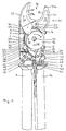
- the front cutter according to the invention has a front housing plate 1 and a rear housing plate 2.
- Both housing plates 1 and 2 are essentially rectangular and are spaced parallel to one another at a distance, wherein they are connected to one another via spacers 3, 4, 5 and 6.
- the spacers 3, 4, 5 and 6 are in pairs in the lateral area of the housing plates 1 and 2, the spacers 3, 4 and 5 being designed as spacer sleeves with an internal thread, which receive screws 7, 8 on both sides, which pass through through openings in the housing plates 1 , 2 are passed.
- the spacer 6 is located in a corner region of the housing plates 1, 2 and has an essentially triangular shape, the hypotenuse being directed inwards. It has a U-shaped cross-sectional profile and is used to hold a holding arm 9 which is connected to the spacer 6 in a form-fitting manner via two fastening pins 10 and 11.
- the fastening pins 10 and 11 run through both an upper end of the holding arm 9 and through the spacer 6 in order to firmly connect the two parts to one another.
- the fastening pins 10 and 11 also pass through both housing plates 1 and 2 in order to lock the spacer 6 and thus the holding arm 9 with respect to the housing plates 1 and 2.
- the axial ends of the fastening pins 10 and 11 are aligned with the outer sides of the housing plates 1 and 2.
- threaded holes 12 are also provided on its two sides, which receive screws 13, which pass through openings in the housing plates Run 1 and 2 through and pull them with their screw head against the spacer 6.
- the z. B. existing steel arm 9 on a U-shaped profile it can be reinforced in its upper region by an internal spacer through which the elements 10, 11 and 13 are also passed.
- the threaded bore 12 can extend into the area of the inner spacer and z. B. be formed as a through hole.
- a swivel arm 14 Adjacent to the holding arm 9 is a swivel arm 14 which is rotatably articulated on the housing plates 1 and 2 via a hinge pin 15.
- the hinge pin 15 runs vertically through the housing plates 1 and 2, the axial end faces of which are aligned with the outer sides of the housing plates 1 and 2.
- a spring not shown, which is effectively located between the holding arm 9 and the swivel arm 14, the swivel arm 14 is pushed away from the holding arm 9 around the hinge pin 15.
- the pivot arm 14 has a U-shaped cross-sectional profile in the region of the hinge pin 15, that is to say in its upper region, and on its upper end face a beveled edge 16 with which it strikes a stop pin 17 when it pivots the most with respect to the holding arm 9 has been.
- the stop pin 17 limits the pivoting movement of the pivot arm 14 away from the holding arm 9.
- the stop pin 17 is mounted in both housing plates 1 and 2.
- a locking pawl 19 which can be rotated about a bearing pin 18 and which can be screwed into a corresponding recess in the rear housing plate 2 when the holding arm 9 and swivel arm 14 are close together in order to give away the swivel arm 14 because of the aforementioned and to prevent spring lying between the holding arm 9 and the swivel arm 14.
- the holding arm 9 and the swivel arm 14 are z. B. encased in plastic to form handles.
- a shaving head 20 which has a front loose knife 21 and a rear loose knife 22. Both loose knives 21 and 22 can be rotated about a common axis of rotation 23 which is supported at the ends in the housing plates 1 and 2.
- the loose knives 21 and 22 have semicircularly curved and mutually facing cutting edges 24 and 25, which together form a pliers jaw 26 of the front cutter. Roughly speaking, the loose knives 21 and 22 are designed like sickles, the axis of rotation 23 coming to lie just below the jaws 26 of the pliers. As a result of the crescent-like design of the loose knives 21 and 22, they still extend beyond the axis of rotation 23 in the direction of the arms 9 and 14, the ends of the loose knives 21 and 22 facing the arms 9 and 14 being rounded and convex regions 27 there and form 28.
- FIG. 1 shows a view of the surface of the rear loose knife 22 on which a bevel 25a for forming the cutting edge 25 is located.
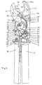
- FIG. 2 shows a view of that surface of the front loose knife 21 on which there is a bevel 24a for forming the cutting edge 24.
- the loose knives 21 and 22 are disc-shaped and relatively thick in the area of the cutting edges 24 and 25, while they are thinner in the convex areas 27, 28, for which purpose their wall surfaces have been removed accordingly, on the opposite or facing sides. This can best be seen in FIG. 1, where in the area of the reference number 29 there is a thinner wall thickness of the loose knife 22 than in the area of the reference number 30. As a result of the removed wall surfaces, a cavity is obtained between the convex areas 27, 28, which for Recording a drive gear 31 is used.
- both loose knives 21 and 22 are prestressed with the aid of a tension spring 32, in such a way that the tension spring 32 tries to move the convex regions 27, 28 towards one another around the axis of rotation 23.
- the drive gear 31 is arranged in a rotationally locking manner on a drive shaft 33, the axial ends of which are mounted in the housing plates 1 and 2.
- the drive shaft 33 is guided through the front housing plate 1 to the front and there has a polygon 34 with which a drive mechanism, not shown, can be coupled, for example a manual adjusting wheel or a motor, to rotate the drive shaft 33.
- the drive mechanism comes to rest on the outside of the front housing plate 1.
- cam disks are arranged on the drive axle 33, namely a front cam disk 35 and a rear cam disk 36, one of which comes to rest on one side of the drive gear 31.
- the gear wheel 31 and the cam disks 35, 36 lie directly on top of one another and are connected to one another in a rotationally locking manner, for example with the aid of pins which pass through common through openings 37, 38 in the parts 31, 35 and 36.
- the drive shaft 33 is rotated from the outside via the drive mechanism, the two cams 35 and 36 as well as the drive gear 31 taken in the same direction. There is no relative movement between them.
- the total axial width of the drive gear 31, cam 35 and cam 36 is so large that this unit comes to fit between the housing plates 1 and 2.
- the axial width of this unit thus coincides with the distance between the housing plates 1 and 2 or with the length of the spacers 3, 4, 5 and 6.
- the cams can still be rotated between the housing plates 1 and 2, so they are not trapped.
- the side walls of the loose knives facing each other are removed in the convex regions 27, 28 in order to create a cavity for receiving the drive gear 31, on the opposite sides of which the convex regions 27, 28 are brought into contact.
- the thickness of the loose knives matches the axial thickness of the cam disks 35, 36.
- the loose knives 21 and 22 also come to lie suitably between the housing plates 1 and 2, specifically also where the convex regions 27 and 28 are located. It should already be pointed out that the convex regions 27, 28 do not always have to be located to the side of the drive gear 31. This depends on the rotational position of the loose knives 21, 22, as will be described.
- the drive axis 33 is seen in the longitudinal direction of the front cutter below the axis of rotation 23, wherein FIG. 1 shows that the convex area 28 of the rear loose knife 22 presses on the circumference of the rear cam 36, while according to FIG. 2 the convex area 27 of the front loose knife 21 presses on the peripheral region of the front cam 35.
- the convex regions 27, 28 are guided against the cams 35, 36 with the aid of the tension spring 32 already mentioned. If the cam disks 35, 36 rotate as a result of the rotation of the drive shaft 33, which can be driven either via the drive gear 31 or via the drive mechanism mentioned, the loose knives 21, 22 are also pivoted. This will be described in more detail later.
- the drive shaft 33 can be rotated with the aid of the drive mechanism mentioned in order to move the loose knives 21, 22 in this way.
- the rotation of the drive shaft 33 can but also take place via the drive gear 31, specifically with the aid of a drive pawl 39 which is pivotably mounted in the upper region of the swivel arm 14 by a bearing pin 40.
- the drive pawl 39 has a drive lug 41 which engages between two teeth 42 of the drive gear 32. Their point of engagement lies on the side of the drive axle 33 on which the holding arm 9 is located.
- a pawl 43 also engages between the teeth 42 of the drive gear 31, which is rotatably mounted on a bearing pin 44, the axial ends of which rest in the housing plates 1 and 2.
- springs 45 and 46 With the help of springs 45 and 46, the drive pawl 39 and the pawl 43 are biased in the direction of the drive gear 31.
- These springs 45, 46 are supported with their other end on the spacer 6 and are wound centrally around pins 47, 48 which pass through the spacer 6 in its U-shaped region.
- the pins 47, 48 are also mounted in the housing plates 1 and 2.
- openings 49 through which adjusting levers 50, 51 are passed, one of which is laterally connected to the drive pawl 39 and the other is laterally connected to the pawl 43.
- the openings 49 are slot openings, so that when the adjusting levers 50, 51 drive pawl 39 and pawl 43 move against the force of the springs 45, 46 can be removed from the drive gear 31. They can be lifted off jointly or separately from the drive gear 31 so that it can also be moved by hand to preset the loose knives 21, 22, specifically via the adjusting wheel already described.
- the securing pawl 19 is first rotated clockwise around the bearing pin 18 in FIG. 1, specifically by hand, to release the swing arm 14.
- the pivot arm 14 is then pivoted away from the holding arm 9 with the aid of the spring, not shown, which is located between the arms 9 and 14, specifically around the hinge pin 15.
- the bearing pin 40 also moves on a path around the hinge pin 15, taking the drive pawl 39 with it, the drive lug 41 of which then slides over the teeth 42 of the drive gear 31.
- the swivel arm 14 If the swivel arm 14 is then rotated around the hinge pin 15 towards the holding arm 9, it presses the drive pawl 39 forward, which in turn rotates the drive gear 31 clockwise about the drive axis 33 via the drive lug 41. In this case, only the pawl 43 slides over the teeth 42 of the drive gear 31 without blocking it. With the rotation of the drive gear 31, the cams 35 and 36 are also rotated clockwise in FIG. 1. The size of the angle of rotation is in agreement with the swivel angle of the swivel arm 14 and usually equals the angular distance between two teeth 42 from one another.
- the cam disk 36 rotates clockwise, that is to say in the direction of the arrow A, that portion of its circumferential area on which the convex area 28 of the rear loose knife 22 comes to rest essentially moves toward the axis of rotation 23.
- the rear cam plate 36 presses the rear loose knife 22 more or less far upward over the convex region 28 and around the axis of rotation 23.
- the rotational position of the rear loose knife 22 is thus determined by the radius of the cam plate 36, which is always selected such that no self-locking or jamming of the cam plate 36 and the convex area 28 can occur.
- the rear loose knife 22 is pivoted farthest to the rear or counterclockwise about the axis of rotation 23, since the convex region 28 touches the cam disk 36 at a circumferential section which is the smallest distance from the drive axis 33. With further rotation of the cam disk 36 and increasing cam disk radius, the rear loose knife 22 is then pressed in the direction of arrow B.
- the front loose knife 21 On the circumference of the front cam 35 is the convex region 27 of the front loose knife 21, so that when the front cam 35 rotates in the direction of arrow A, the front loose knife 21 in FIG. 2 is rotated clockwise around the axis of rotation 23, the rotational position of which again depends on the radius of the cam disc 35. In FIG. 2, the front loose knife 21 assumes its most pivoted downward position since the convex region 27 comes to rest on the front cam disc 35 where it has its smallest radius.
- the front cam 35 If the front cam 35 is rotated from this in the direction of arrow A, it presses the front loose knife 21 over the convex region 27 in the direction of arrow C to close the jaws 26, since at the same time the rear loose knife 22 is moved through the rear cam 36 is pressed in the direction of arrow B. In order to achieve this, the rotational positions of the cam disks 35 and 36 relative to the drive gear 31 have been selected from the start.
- the unit consisting of the cam plate 35, drive gear 31 and cam plate 36 can also be rotated by hand, specifically via a polygon 34 seated handwheel in order to be able to open and close the jaws 26 in the desired manner when the handwheel is rotated.
- the angle of deflection of the loose knives 21 and 22 can be preset, in order in this way to be predetermined at successive rotational positions of the drive gear 31 Generate cutting forces.
- a strand-like material can then be cut with a desired and rotational position-dependent force profile, which is particularly advantageous in the case of cables which have a relatively soft insulation and a harder core.
- the radii of the cams can be selected so that the jaws are closed faster at the same angular steps of the drive gear 31, since only a soft insulation needs to be cut, while then a slower movement of the loose knives 21, 22 takes place per angular step of the drive gear 31 , because now the hard cable core is cut.
- the front cutter is also suitable for cutting cables laid in corners, since it has only a small structural width.
- the front cutter can also be sealed in the end region of the drive gear 31 and the cam disks 35, 36 in order to obtain protection against contamination of the gearbox.
Landscapes
- Life Sciences & Earth Sciences (AREA)
- Forests & Forestry (AREA)
- Engineering & Computer Science (AREA)
- Mechanical Engineering (AREA)
- Scissors And Nippers (AREA)
- Knives (AREA)
- Harvester Elements (AREA)
- Shearing Machines (AREA)
- Folding Of Thin Sheet-Like Materials, Special Discharging Devices, And Others (AREA)
- Control And Other Processes For Unpacking Of Materials (AREA)
- Threshing Machine Elements (AREA)
Applications Claiming Priority (2)
| Application Number | Priority Date | Filing Date | Title |
|---|---|---|---|
| DE4209530A DE4209530C1 (fr) | 1992-03-24 | 1992-03-24 | |
| DE4209530 | 1992-03-24 |
Publications (3)
| Publication Number | Publication Date |
|---|---|
| EP0562242A2 true EP0562242A2 (fr) | 1993-09-29 |
| EP0562242A3 EP0562242A3 (fr) | 1994-02-09 |
| EP0562242B1 EP0562242B1 (fr) | 1997-01-02 |
Family
ID=6454880
Family Applications (1)
| Application Number | Title | Priority Date | Filing Date |
|---|---|---|---|
| EP93101551A Expired - Lifetime EP0562242B1 (fr) | 1992-03-24 | 1993-02-02 | Pince coupante devant |
Country Status (6)
| Country | Link |
|---|---|
| US (1) | US5331742A (fr) |
| EP (1) | EP0562242B1 (fr) |
| JP (1) | JP2518591B2 (fr) |
| AT (1) | ATE147002T1 (fr) |
| DE (2) | DE4209530C1 (fr) |
| TW (1) | TW311297B (fr) |
Families Citing this family (17)
| Publication number | Priority date | Publication date | Assignee | Title |
|---|---|---|---|---|
| DE4312469C2 (de) * | 1993-04-16 | 1996-01-04 | Laux Friedrich G | Schneidgerät für stangenförmige Werkstücke, insbesondere für laminiertes Flachband |
| EP1006627A1 (fr) * | 1998-12-02 | 2000-06-07 | Marvel Corporation | Outil à main pour le sertissage d'un contact |
| US6523266B2 (en) * | 2000-01-12 | 2003-02-25 | Chung-Cheng Yang | Shears |
| US6766581B2 (en) * | 2001-05-16 | 2004-07-27 | Greenlee Textron Inc. | Cable cutter/crimper mechanism |
| US20060277764A1 (en) * | 2005-06-14 | 2006-12-14 | Chih-Ching Hsien | Power-saving scissors |
| US7331109B2 (en) * | 2006-05-12 | 2008-02-19 | Shu-Woan Tu | Electric cutting device |
| US9486864B2 (en) | 2007-07-03 | 2016-11-08 | Milwaukee Electric Tool Corporation | Pipe cutter |
| WO2009006596A1 (fr) * | 2007-07-03 | 2009-01-08 | Milwaukee Electric Tool Corporation | Coupe-tube |
| DE102009059198A1 (de) * | 2009-12-17 | 2011-06-22 | KNIPEX-Werk C. Gustav Putsch KG, 42349 | Zange |
| WO2012033540A2 (fr) * | 2010-09-10 | 2012-03-15 | Panosian Michael H | Coupe-boulon compact à puissance améliorée |
| US9339938B2 (en) | 2010-10-08 | 2016-05-17 | Milwaukee Electric Tool Corporation | Powered cutting tool |
| USD668922S1 (en) | 2012-01-20 | 2012-10-16 | Milwaukee Electric Tool Corporation | Powered cutting tool |
| CN102825178B (zh) * | 2012-09-17 | 2015-02-25 | 刘声遥 | 前开口式金属线缆剪切器 |
| TWM479006U (zh) * | 2014-01-28 | 2014-06-01 | huai-rong Zhou | 免切換之多模式修枝剪 |
| CN204149213U (zh) * | 2014-08-26 | 2015-02-11 | 宁波爱特工具有限公司 | 裁管刀 |
| DE102015206959A1 (de) * | 2015-04-17 | 2016-10-20 | Robert Bosch Gmbh | Schneidevorrichtung |
| EP3159088B1 (fr) * | 2015-10-23 | 2018-12-05 | Wezag GmbH Werkzeugfabrik | Pince manuelle |
Citations (3)
| Publication number | Priority date | Publication date | Assignee | Title |
|---|---|---|---|---|
| DE3302875C2 (fr) * | 1983-01-28 | 1987-11-12 | Baudat E. Wolter Kg, 7941 Duermentingen, De | |
| US4876794A (en) * | 1988-07-13 | 1989-10-31 | Radia-Cam Inc. | Variable mechanical advantage device utilizing a radial cam |
| US5074142A (en) * | 1990-09-25 | 1991-12-24 | Burndy Corporation | Crimping tool having a cam roller brake |
Family Cites Families (10)
| Publication number | Priority date | Publication date | Assignee | Title |
|---|---|---|---|---|
| US3324702A (en) * | 1965-01-19 | 1967-06-13 | Burndy Corp | Damped compression tool |
| CH595194A5 (fr) * | 1975-08-25 | 1978-02-15 | Felix Flisch | |
| DE2745114C2 (de) * | 1977-10-07 | 1983-01-05 | Baudat E. Wolter KG, 7941 Dürmentingen | Tragbare Schere, insbesondere zum Kabelschneiden |
| DE2832561C3 (de) * | 1978-07-25 | 1981-01-22 | Reiner 3570 Stadt Allendorf Rommel | Handbetätigte Schere mit um das Werkstück, insbesondere Kabel, Äste, Profile o.dgl. herumlegbarer Schneidbacke |
| DE2910544A1 (de) * | 1979-03-17 | 1980-09-25 | Wolter Baudat E Kg | Schere insbesondere kabelschneider |
| JPS6142740Y2 (fr) * | 1980-12-05 | 1986-12-04 | ||
| DE8219141U1 (de) * | 1982-07-03 | 1983-12-22 | Baudat E. Wolter KG, 7941 Dürmentingen | Schere zum Schneiden von strangförmigem Gut |
| JPS6174322U (fr) * | 1984-10-23 | 1986-05-20 | ||
| JPS62148113A (ja) * | 1985-12-20 | 1987-07-02 | Kobayashi Kogu Seisakusho:Kk | 手動式ケ−ブルカツタ− |
| DD253781A1 (de) * | 1986-11-20 | 1988-02-03 | Schmalkalden Werkzeug | Hebelschneidzange, insbesondere bolzenschneider |
-
1992
- 1992-03-24 DE DE4209530A patent/DE4209530C1/de not_active Expired - Fee Related
- 1992-03-28 TW TW081102396A patent/TW311297B/zh active
-
1993
- 1993-02-02 EP EP93101551A patent/EP0562242B1/fr not_active Expired - Lifetime
- 1993-02-02 DE DE59304933T patent/DE59304933D1/de not_active Expired - Fee Related
- 1993-02-02 AT AT93101551T patent/ATE147002T1/de not_active IP Right Cessation
- 1993-03-16 JP JP5055273A patent/JP2518591B2/ja not_active Expired - Lifetime
- 1993-03-22 US US08/035,171 patent/US5331742A/en not_active Expired - Fee Related
Patent Citations (3)
| Publication number | Priority date | Publication date | Assignee | Title |
|---|---|---|---|---|
| DE3302875C2 (fr) * | 1983-01-28 | 1987-11-12 | Baudat E. Wolter Kg, 7941 Duermentingen, De | |
| US4876794A (en) * | 1988-07-13 | 1989-10-31 | Radia-Cam Inc. | Variable mechanical advantage device utilizing a radial cam |
| US5074142A (en) * | 1990-09-25 | 1991-12-24 | Burndy Corporation | Crimping tool having a cam roller brake |
Also Published As
| Publication number | Publication date |
|---|---|
| JPH0615523A (ja) | 1994-01-25 |
| EP0562242A3 (fr) | 1994-02-09 |
| US5331742A (en) | 1994-07-26 |
| TW311297B (fr) | 1997-07-21 |
| ATE147002T1 (de) | 1997-01-15 |
| EP0562242B1 (fr) | 1997-01-02 |
| DE4209530C1 (fr) | 1993-07-08 |
| JP2518591B2 (ja) | 1996-07-24 |
| DE59304933D1 (de) | 1997-02-13 |
Similar Documents
| Publication | Publication Date | Title |
|---|---|---|
| EP0562242B1 (fr) | Pince coupante devant | |
| DE2642008C3 (de) | Handzange zum Abisolieren von Leiterenden | |
| WO2014012780A1 (fr) | Instrument endoscopique | |
| DE3724999A1 (de) | Von hand betaetigbarer kabeltrenner oder kabelschneider | |
| EP0186222B1 (fr) | Dispositif de coupe manuel | |
| DE102009014096A1 (de) | Motorisches Schneidegerät für den Garten mit austauschbaren Schneidblättern | |
| DE102018111873A1 (de) | Presszange | |
| EP2261445A2 (fr) | Serrure, notamment serrure de porte dotée d'un mécanisme de fermeture amélioré | |
| DE2850801A1 (de) | Rasiergeraet | |
| DE1927032A1 (de) | Elektrischer Trockenrasierer | |
| EP0735638B1 (fr) | Pince à dénuder | |
| EP0113655B2 (fr) | Poignée de porte | |
| EP0925893A2 (fr) | Dispositif pour rainurer des pairos à profondeur de coupe ajustable | |
| EP0547386A1 (fr) | Appareil à épiler | |
| EP1571116B1 (fr) | Tête de vissage | |
| DE102010007917B4 (de) | Handbetätigtes Werkzeug | |
| EP0437257B1 (fr) | Arrangement de transmission | |
| EP3488972B1 (fr) | Dispositif de pivotement | |
| EP0355306A1 (fr) | Dispositif d'entraînement, notamment pour toits ouvrants coulissants, toits ouvrants coulissants pivotants, fenêtres ou similaires | |
| DE3302875A1 (de) | Schere zum querunterteilen von strangfoermigem schneidgut | |
| DE60200659T2 (de) | Irreversibel oder reversibel regelbare Bewegungsübertragungsvorrichtung für einen motorisierten Tür- und Torantrieb. | |
| DE3825909C2 (fr) | ||
| CH669636A5 (fr) | ||
| DE3247947C2 (de) | Gelenkbeschlag für einen Fahrzeugsitz | |
| DE8219141U1 (de) | Schere zum Schneiden von strangförmigem Gut |
Legal Events
| Date | Code | Title | Description |
|---|---|---|---|
| PUAI | Public reference made under article 153(3) epc to a published international application that has entered the european phase |
Free format text: ORIGINAL CODE: 0009012 |
|
| AK | Designated contracting states |
Kind code of ref document: A2 Designated state(s): AT CH DE ES FR GB IT LI SE |
|
| PUAL | Search report despatched |
Free format text: ORIGINAL CODE: 0009013 |
|
| AK | Designated contracting states |
Kind code of ref document: A3 Designated state(s): AT CH DE ES FR GB IT LI SE |
|
| RHK1 | Main classification (correction) |
Ipc: B26B 13/00 |
|
| 17P | Request for examination filed |
Effective date: 19940119 |
|
| 17Q | First examination report despatched |
Effective date: 19951117 |
|
| GRAG | Despatch of communication of intention to grant |
Free format text: ORIGINAL CODE: EPIDOS AGRA |
|
| GRAH | Despatch of communication of intention to grant a patent |
Free format text: ORIGINAL CODE: EPIDOS IGRA |
|
| GRAH | Despatch of communication of intention to grant a patent |
Free format text: ORIGINAL CODE: EPIDOS IGRA |
|
| GRAA | (expected) grant |
Free format text: ORIGINAL CODE: 0009210 |
|
| AK | Designated contracting states |
Kind code of ref document: B1 Designated state(s): AT CH DE ES FR GB IT LI SE |
|
| PG25 | Lapsed in a contracting state [announced via postgrant information from national office to epo] |
Ref country code: IT Free format text: LAPSE BECAUSE OF FAILURE TO SUBMIT A TRANSLATION OF THE DESCRIPTION OR TO PAY THE FEE WITHIN THE PRESCRIBED TIME-LIMIT;WARNING: LAPSES OF ITALIAN PATENTS WITH EFFECTIVE DATE BEFORE 2007 MAY HAVE OCCURRED AT ANY TIME BEFORE 2007. THE CORRECT EFFECTIVE DATE MAY BE DIFFERENT FROM THE ONE RECORDED. Effective date: 19970102 Ref country code: GB Effective date: 19970102 Ref country code: ES Free format text: THE PATENT HAS BEEN ANNULLED BY A DECISION OF A NATIONAL AUTHORITY Effective date: 19970102 |
|
| REF | Corresponds to: |
Ref document number: 147002 Country of ref document: AT Date of ref document: 19970115 Kind code of ref document: T |
|
| REG | Reference to a national code |
Ref country code: CH Ref legal event code: EP |
|
| REF | Corresponds to: |
Ref document number: 59304933 Country of ref document: DE Date of ref document: 19970213 |
|
| ET | Fr: translation filed | ||
| PG25 | Lapsed in a contracting state [announced via postgrant information from national office to epo] |
Ref country code: SE Effective date: 19970402 |
|
| REG | Reference to a national code |
Ref country code: CH Ref legal event code: NV Representative=s name: A. BRAUN, BRAUN, HERITIER, ESCHMANN AG PATENTANWAE |
|
| GBV | Gb: ep patent (uk) treated as always having been void in accordance with gb section 77(7)/1977 [no translation filed] |
Effective date: 19970102 |
|
| PLBE | No opposition filed within time limit |
Free format text: ORIGINAL CODE: 0009261 |
|
| STAA | Information on the status of an ep patent application or granted ep patent |
Free format text: STATUS: NO OPPOSITION FILED WITHIN TIME LIMIT |
|
| 26N | No opposition filed | ||
| PGFP | Annual fee paid to national office [announced via postgrant information from national office to epo] |
Ref country code: FR Payment date: 19980116 Year of fee payment: 6 |
|
| PGFP | Annual fee paid to national office [announced via postgrant information from national office to epo] |
Ref country code: AT Payment date: 19980121 Year of fee payment: 6 |
|
| PGFP | Annual fee paid to national office [announced via postgrant information from national office to epo] |
Ref country code: CH Payment date: 19980203 Year of fee payment: 6 |
|
| PG25 | Lapsed in a contracting state [announced via postgrant information from national office to epo] |
Ref country code: AT Free format text: LAPSE BECAUSE OF NON-PAYMENT OF DUE FEES Effective date: 19990202 |
|
| PG25 | Lapsed in a contracting state [announced via postgrant information from national office to epo] |
Ref country code: LI Free format text: LAPSE BECAUSE OF NON-PAYMENT OF DUE FEES Effective date: 19990228 Ref country code: CH Free format text: LAPSE BECAUSE OF NON-PAYMENT OF DUE FEES Effective date: 19990228 |
|
| REG | Reference to a national code |
Ref country code: CH Ref legal event code: PL |
|
| PG25 | Lapsed in a contracting state [announced via postgrant information from national office to epo] |
Ref country code: FR Free format text: LAPSE BECAUSE OF NON-PAYMENT OF DUE FEES Effective date: 19991029 |
|
| REG | Reference to a national code |
Ref country code: FR Ref legal event code: ST |
|
| PGFP | Annual fee paid to national office [announced via postgrant information from national office to epo] |
Ref country code: DE Payment date: 20000122 Year of fee payment: 8 |
|
| PG25 | Lapsed in a contracting state [announced via postgrant information from national office to epo] |
Ref country code: DE Free format text: LAPSE BECAUSE OF NON-PAYMENT OF DUE FEES Effective date: 20011201 |