EP0555176A1 - Gerät zur Herstellung von Backwaren, insbesondere Pizzas - Google Patents
Gerät zur Herstellung von Backwaren, insbesondere Pizzas Download PDFInfo
- Publication number
- EP0555176A1 EP0555176A1 EP93810020A EP93810020A EP0555176A1 EP 0555176 A1 EP0555176 A1 EP 0555176A1 EP 93810020 A EP93810020 A EP 93810020A EP 93810020 A EP93810020 A EP 93810020A EP 0555176 A1 EP0555176 A1 EP 0555176A1
- Authority
- EP
- European Patent Office
- Prior art keywords
- hood
- burner
- support plate
- baked goods
- openings
- Prior art date
- Legal status (The legal status is an assumption and is not a legal conclusion. Google has not performed a legal analysis and makes no representation as to the accuracy of the status listed.)
- Granted
Links
Images


Classifications
-
- A—HUMAN NECESSITIES
- A47—FURNITURE; DOMESTIC ARTICLES OR APPLIANCES; COFFEE MILLS; SPICE MILLS; SUCTION CLEANERS IN GENERAL
- A47J—KITCHEN EQUIPMENT; COFFEE MILLS; SPICE MILLS; APPARATUS FOR MAKING BEVERAGES
- A47J37/00—Baking; Roasting; Grilling; Frying
- A47J37/06—Roasters; Grills; Sandwich grills
- A47J37/0623—Small-size cooking ovens, i.e. defining an at least partially closed cooking cavity
- A47J37/0647—Small-size cooking ovens, i.e. defining an at least partially closed cooking cavity with gas burners
-
- A—HUMAN NECESSITIES
- A47—FURNITURE; DOMESTIC ARTICLES OR APPLIANCES; COFFEE MILLS; SPICE MILLS; SUCTION CLEANERS IN GENERAL
- A47J—KITCHEN EQUIPMENT; COFFEE MILLS; SPICE MILLS; APPARATUS FOR MAKING BEVERAGES
- A47J36/00—Parts, details or accessories of cooking-vessels
- A47J36/06—Lids or covers for cooking-vessels
-
- A—HUMAN NECESSITIES
- A47—FURNITURE; DOMESTIC ARTICLES OR APPLIANCES; COFFEE MILLS; SPICE MILLS; SUCTION CLEANERS IN GENERAL
- A47J—KITCHEN EQUIPMENT; COFFEE MILLS; SPICE MILLS; APPARATUS FOR MAKING BEVERAGES
- A47J37/00—Baking; Roasting; Grilling; Frying
- A47J37/06—Roasters; Grills; Sandwich grills
- A47J37/0623—Small-size cooking ovens, i.e. defining an at least partially closed cooking cavity
- A47J37/0629—Small-size cooking ovens, i.e. defining an at least partially closed cooking cavity with electric heating elements
-
- A—HUMAN NECESSITIES
- A47—FURNITURE; DOMESTIC ARTICLES OR APPLIANCES; COFFEE MILLS; SPICE MILLS; SUCTION CLEANERS IN GENERAL
- A47J—KITCHEN EQUIPMENT; COFFEE MILLS; SPICE MILLS; APPARATUS FOR MAKING BEVERAGES
- A47J37/00—Baking; Roasting; Grilling; Frying
- A47J37/06—Roasters; Grills; Sandwich grills
- A47J37/0623—Small-size cooking ovens, i.e. defining an at least partially closed cooking cavity
- A47J37/0658—Small-size cooking ovens, i.e. defining an at least partially closed cooking cavity specially adapted for cooking pizza
Definitions
- the invention relates to a device according to the preamble of claim 1.
- the object to be achieved with the invention is to create a device for the production of baked goods, in particular for the simultaneous production of several pizzas, which is intended to be placed on a table and with which a balanced top and bottom heat can be achieved and the cooking steam is not dripping onto the baked goods.
- the hood made of unglazed stoneware, in particular microporous fired clay, absorbs the cooking steam to such an extent that no wet precipitation forms on the baked goods. It also shows that such a stoneware hood brings about a significant improvement in the taste of the baked goods, since the hood reflects the aroma substances.
- This tabletop device contains a lower part 2, usually made of sheet steel, with heat-insulating feet 11 and an upper part designed as a hood 3.
- This dome-like hood 3 consists of a ceramic material in the form of a sintered, unglazed stoneware, in particular of fired flame-resistant microporous clay.
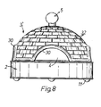
- the hood 3 is smooth on the inside and can be provided on the outside with decorative decorations, for example grooves 32 made in the manner of a brick wall.
- the hood 3 is provided with several loading openings 4.
- hood 3 Usually there are three segment-like loading openings 4, which are arranged at the lower edge of the hood and are distributed around the circumference of the hood 3 and are open at the bottom.
- the wall thickness of the hood 3 is preferably provided with a bead-like thickening 30 around the loading openings.
- a heat-insulating handle or knob 5 is provided at the top.
- a burner is understood to mean a flame burner with gaseous, liquid or pasty fuel.
- three burners 6 are distributed around the circumference and are arranged offset with respect to the loading openings, so that each burner is located between two adjacent loading openings.
- the burners 6 rest on an intermediate floor 24 of the lower part 2.
- Fig. 4 shows a plan view of this intermediate floor 24 with recesses 34 for receiving the burner housing. These recesses define the radial insertion depth of the burners 6, since they have to assume a predetermined position.
- the burners 6 each lie on this intermediate floor 24 with a shoulder 38 and are at a short distance from the floor 40.
- a disk-shaped heat distribution plate 7 which is designed as a cover of the lower part 2.
- This heat spreader 7 is provided in the edge area with openings 22 which are arranged in segments.
- This heat distribution plate 7 is usually connected to the base via a central support 13 to the floor 24 in a fixed or removable manner.
- the openings 22 can be holes or slots.
- heat deflection plates 28 there are three heat deflection plates 28, each arranged in the area of the openings 22, which according to FIG. 5 have an angle ⁇ of approximately 64 ° to the horizontal. At centering angle ⁇ of these heat deflection plates 28 is less than 60 °, preferably about 50 °. They also serve for the correct positioning of the hood 3, in that if the hood 3 is fitted incorrectly, these heat deflection plates would hinder access to the loading openings 4.
- a support disc is located at a vertical distance of 1-2 cm above the heat distribution plate 7 10 for supporting the blades 18 receiving the baked goods 21.
- This support disk 10 is preferably made of metal, for example aluminum.
- the support disk 10 has a diameter which is smaller than that of the heat distribution plate 7 and lies loosely on a plurality of supports 12 arranged at the circumference. There is thus an annular space 16 of the support disk 10 with respect to the inside 15 of the hood edge of the width c.
- the burners 6 are used in openings 14 in the jacket 42 of the lower part 2 below the openings 22 of the heat distribution plate 7 lying on the intermediate floor 24.
- the burner openings 44 are located partly vertically below the edge of the heat distribution plate 7 and partly in the area of the intermediate space 16.
- the hot gases generated by the burner 6 act on the perforated heat distribution plate 7 and cause the intermediate space 9 to be heated. This has the effect that the heat is relatively low large area of the support plate 10 is distributed and the support plate 10 is largely evenly heated, although it is heated only by three selectively arranged heat sources.
- some of the hot gases heated by the burner 6 flow into the annular space 16 and from there along the curved inner edge 15 of the hood 3 into the hood dome 20. This creates an optimal distribution between top heat and bottom heat, so that the baked goods are baked evenly.
- the baked goods 21, for example a previously prepared, relatively small pizza, are pushed into the interior of the hood 3 on a shovel 18 provided with a handle 19 and handle 17, preferably perforated, through the loading openings 4, the baked goods 21 being on this during the baking time Blade 18 remains.
- the loading opening 4 is preferably dimensioned so large that at the same time there is space for two blades 18 laterally next to one another.
- This is ring-shaped, the diameter being smaller than the diameter of the support disk 10.
- a connecting piece 26 of this heating element 25 is rigidly connected to the cover plate 23 of the lower part and leads to a connection plug 27 on the jacket 42 of the lower part 2.
- the annular heating element 25 is in a range between 1/2 and 2/3 of the distance between the support plate 10 and the zenith of the hood 3, preferably the distance a is about 4.5 cm and the distance b is about 7 cm, with a diameter of the annular electrical Radiator 28 by 20 cm.
- the hood 3 ' is preferably provided with four charging openings 18 distributed around the circumference. Even if there are four pizzas 21 in the interior of the hood 3 'at the same time, they do not cover the entire surface of the support disk 10 heated up and thereby gives bottom heat, which heats the baked goods from the bottom, at the same time the air in the interior of the hood 3 'is heated by the radiator 25, which acts as top heat.
- a second radiator 33 below the support plate 10 in the space 9 above the cover plate 23.
- This second radiator 33 also has a ring shape, the diameter being smaller than the first radiator ring 25, as can be seen from FIG. 7.
- the heating power of the lower, second radiator 33 is smaller than that of the first upper radiator 25. If the current consumption of the first radiator 25 is 500 watts, for example, the second radiator 33 is dimensioned such that it simultaneously absorbs approximately 300 watts.
- the device can also be used for raclettes.
Abstract
Description
- Die Erfindung bezieht sich auf ein Gerät nach dem Oberbegriff des Patentanspruches 1.
- Bei der Herstellung von Backwaren, wie Pizzas, od.dgl. ist ein ausgewogenes Verhältnis zwischen Oberhitze und Unterhitze erforderlich, damit eine gleichmässiger Backvorgang stattfinder. Bei nicht-gewerblichen Backöfen, namentlich bei Tischgeräten, besteht beim Backen von Pizzas od.dgl. ein Problem darin, dass diese ungleichmässig gebacken werden und auf ihrer Oberseite oder Unterseite zu nass und zu wenig knusprig werden oder bei zu viel Wärme anbrennen.
- Die mit der Erfindung zu lösende Aufgabe besteht darin, eine Gerät zur Herstellung von Backwaren, insbesondere zur gleichzeitigen Herstellung mehrerer Pizzas zu schaffen, das zum Aufstellung auf einem Tisch bestimmt ist und mit dem eine ausgeglichene Ober- und Unterhitze erreichbar ist und der Kochdampf sich nicht nässend auf das Backgut niederschlägt.
- Die Aufgabe wird durch die im Kennzeichen des Patentanspruches 1 genannten Merkmale gelöst.
- Dadurch gelingt es eine gute Wärmeverteilung für Backgut zu erreichen, wobei ein ausgewogenes Verhältnis zwischen Oberhitze und Unterhitze erreicht wird. Andererseits nimmt die aus unglasiertem Steinzeug, insbesondere mikroporösem gebranntem Ton bestehende Haube den Kochdampf soweit auf, dass sich auf dem Backgut keine nassen Niederschläge bilden. Es zeigt sich überdies, dass eine derartige Steinzeug-Haube eine bedeutende Geschmacksverbesserung des Backgutes bewirkt, da die Haube die Aromastoffe reflektiert.
- In der Zeichnung sind zwei Ausführungsbeispiele des Erfindungsgegenstandes dargestellt. Es zeigen:
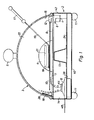
- Fig. 1 einen Vertikalschnitt durch das Gerät mit Brennerbeheizung
- Fig. 2 eine perspektivische Ansicht des Gerätes ohne Haube
- Fig. 3 eine Draufsicht auf eine Wärmeverteilplatte
- Fig. 4 eine Draufsicht auf eine Zwischenboden
- Fig. 5 eine Draufsicht auf eine Stützblech für die Brenner
- Fig. 6 einen Vertikalschnitt durch das Gerät mit elektrischer Beheizung
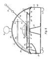
- Fig. 7 eine perspektivische Darstellung des Gerätes ohne Haube mit elektrischen Heizkörpern
- Fig. 8 eine Ansicht des Gerätes samt Haube
- Das Gerät gemäss der Fig. 1 dient zur nicht-gewerblichen Herstellung von Backwaren, insbesondere Pizzas. Das Gerät wird im Haushalt normalerweise auf einem Tisch aufgestellt wobei mehrere Personen gleichzeitig Pizzas od.dgl. backen können. Dieses Tischgerät enthält einen üblicherweise aus Stahlblech bestehenden Unterteil 2 mit wärmeisolierenden Füssen 11 und einem als Haube 3 ausgebilden Oberteil. Diese domartige Haube 3 besteht aus einem keramischen Werkstoff in Form eines gesinterten, unglasierten Steinzeug, insbesondere aus gebranntem flammfestem mikroporösem Ton. Die Haube 3 ist innen glatt und kann aussen mit dekorativen Verzierungen, beispielsweise backsteinmauerartig angebrachten Rillen 32 versehen sein. Die Haube 3 ist mit mehreren Beschickungsöffnungen 4 versehen. Ueblicherweise sinds am untern Haubenrand drei am Umfang der Haube 3 verteilt angeordnete, unten offene, segmentartige Beschickungsöffnungen 4 vorhanden. Um die Beschickungsöffnungen herum ist die Wandstärke der Haube 3 vorzugsweise mit je einer wulstartigen Verdickung 30 versehen. Zum Abheben der lose aufgesetzten Haube 3 vom Unterteil 2 ist oben ein wärmeisolierender Griff oder Knauf 5 vorhanden.
- Bei der Ausführungsform nach Fig. 1 befinden sich im Unterteil 2 mehrere Brenner 6. Unter Brenner wird ein Flammenbrenner mit gasförmigen, flüssigem oder pastösem Brennstoff verstanden. Bei drei Beschickungsöffnungen sind drei Brenner 6 am Umfang verteilt vorhanden, die gegenüber den Be schickungs- öffnungen versetzt angeordnet sind, sodass also jeder Brenner sich zwischen zwei benachbarten Beschickungsöffnungen befindet. Die Brenner 6 liegen auf einem Zwischenboden 24 des Unterteiles 2 auf.
- Fig. 4 zeigt eine Draufsicht auf diesen Zwischenboden 24 mit Ausnehmungen 34 für die Aufnahme der Brennergehäuse. Diese Ausnehmungen definieren die radiale Einschubstiefe der Brenner 6, da diese eine vorbestimmte Position einnehmen müssen. Die Brenner6 liegen aufdiesemZwischenboden 24 je mit einer Schulter 38 auf und haben zum Boden 40 einen geringen Abstand.
- Oberhalb der Brenner 6 befindet sich eine scheibenförmige Wärmeverteilerplatte 7, die als Deckel des Unterteiles 2 ausgebildet ist. Dieser Wärmeverteiler 7 ist im Randbereich mit Durchbrüchen 22 versehen, die segmentartig angeordnet sind. Diese Wärmeverteilerplatte 7 ist üblicherweise mit dem Unterteil über eine zentrale Stütze 13 mit dem Boden 24 festoderwegnehmbarverbunden. Die Durchbrüche 22 können Löcher oder Schlitze sein. Vorzugsweise ist eine radial äusserste Lochreihe 36 mit grösseren Löchern gegenüber den übrigen Löchern 37 vorhanden, wie dies aus Fig. 3 hervorgeht.
- Mit der Wärmeverteilplatte 7 sind drei je im Bereich der Durchbrüche 22 am äusseren Rand angeordnete Wärmeumlenk-Schilder 28 vorhanden, die gemäss Fig. 5 zur Horizontalen einen Winkel a von etwa 64° haben. Bei Zentrierwinkel β dieser Wärmeumlenk-Schilder 28 ist kleiner als 60°, vorzugsweise etwa 50°. Sie dienen zugleich der richtigen Positionierung der Haube 3, indem bei unrichtigem Aufsetzen der Haube 3 diese Wärmeumlenk-Schilder den Zugang zu den Beschickungsöffnungen 4 behindern würden.
- In einem vertikalen Abstand von 1-2 cm oberhalb der Wärmeverteilplatte 7 befindet sich eine Tragscheibe 10 zur Abstützung der das Backgut 21 aufnehmenden Schaufeln 18. Diese Tragscheibe 10 besteht vorzugsweise aus Metall beispielsweise Aluminium. Die Tragscheibe 10 hat einen Durchmesser der kleiner ist als der der Wärmeverteilplatte 7 und liegt lose auf mehreren am Unfang verteilt angeordneten Stützen 12 auf. Somit besteht ein ringförmiger Zwischenraum 16 der Tragscheibe 10 gegenüber der Innenseite 15 des Haubenrandes von der Breite c.
- Die Brenner 6 werden in Oeffnungen 14 im Mantel 42 des Unterteiles 2 unterhalb den Durchbrüchen 22 der Wärmeverteilplatte 7 auf dem Zwischenboden 24 aufliegend eingesetzt. Die Brenneröffnungen 44 befinden sich je teilweise vertikal unterhalb des Randes der Wärmeverteilplatte 7 und teilweise im Bereich des Zwischenraumes 16. Die vom Brenner 6 erzeugten Heissgase beaufschlagen die gelochte Wärmeverteilplatte 7 und bewirken eine Erwärmung des Zwischenraumes 9. Dies bewirkt, dass die Wärme auf eine relativ gross Fläche der Tragscheibe 10 verteilt wird und die Tragscheibe 10 weitgehend gleichmässig erwärmt wird, obschon sie nur von drei punktuell angeordneten Wärmequellen erhitzt wird. Ausserdem strömt ein Teil der vom Brenner 6 erhitzten Heissgase in den ringförmigen Zwischenraum 16 und von dort dem gewölbten Innenrand 15 der Haube 3 entlang in die Haubenkuppel 20. Dadurch entsteht eine optimale Verteilung zwischen Oberhitze und Unterhitze, sodass das Backgut gleichmässig gebacken wird. Im Boden 40 und im Zwischenboden 24 befinden sich Luftlöcher 49.
- Das Backgut 21, beispielsweise eine vorgängig vorbereitete, relativ kleine Pizza, wird auf einer mit einem Stiel 19 und Griff 17 versehenen, vorzugsweise gelochten Schaufel 18 durch die Beschickungsöffnungen 4 in das Innere der Haube 3 eingeschoben, wobei das Backgut 21 während der Backzeit auf dieser Schaufel 18 verbleibt.
- Nach Ablauf der Backzeit wird es auf dieser Schaufel aus der Beschickungsöffnung 4 herausgezogen. Die Beschickungsöffnung 4 wird vorzugsweise so gross dimensioniert, dass gleichzeitig zwei Schaufeln 18 seitlich nebeneinander Platz haben.
- Es hat sich als zweckmässig erwiesen die Haube 3 mit drei Beschickungsöffnungen und mit drei Brennern 6 zu versehen.
- In den Fig. 6 - 8 ist eine Ausführungsform mit elektrischer Beheizung dargestellt. In diesen Figuren bedeuten gleiche Bezugszahlen gleiche Teile mit gleichen Funktionen. An Stelle der Brenner befindet sich hier oberhalb der Tragplatte 10 ein erster elektrischer Heizkörper 25.
- Dieser ist ringförmig ausgebildet, wobei der Durchmesser kleiner ist als der Durchmesser der Tragscheibe 10. Ein Verbindungsstück 26 dieses Heizkörpers 25 ist mit der Deckplatte 23 des Unterteiles starr verbunden und führt zu einem Anschluss-Stecker 27 am Mantel 42 des Unterteiles 2. Der ringförmige Heizkörper 25 befindet sich in einem Bereich zwischen 1/2 und 2/3 des Abstandes zwischen Tragscheibe 10 und dem Zenit der Haube 3, vorzugsweise beträgt der Abstand a etwa 4,5 cm und der Abstand b etwa 7 cm, bei einem Durchmesser des ringförmigen elektrischen Heizkörpers 28 von 20 cm.
- Bei dieser elektrischen Ausführungsform wird die Haube 3' vorzugsweise mit vier am Umfang verteilte Beschickungsöffnungen 18 versehen. Selbst wenn sich gleichzeitig vier Pizzas 21 im Innern der Haube 3' befinden, bedecken diese nicht die ganze Fläche der Tragscheibe 10. Da die Tragscheibe 10 aus einem gut wärmeleitenden Material, beispielsweise Aluminium besteht, wird die Tragscheibe 10 durch Strahlungswärme des Heizkörpers 25 von oben her aufgeheizt und ergibt dadurch Unterhitze, welche des Backgut vom Boden her erwärmt, gleichzeitig wird die Luft im Innenraum der Haube 3' vom Heizkörper 25 erwärmt, die als Oberhitze wirkt.
- Zur Beschleunigung des Backvorganges ist es zweckmässig einen zweiten Heizkörpers 33 unterhalb der Tragplatte 10 im Zwischenraum 9 oberhalb der Deckplatte 23 anzuordnen. Dieser zweite Heizkörper 33 hat ebenfalls Ringform, wobei der Durchmesser kleiner ist als der erste Heizkörperring 25, wie dies aus Fig. 7 hervorgeht. Die Heizleistung des untern, zweiten Heizkörpers 33 ist kleiner als des ersten obern Heizkörpers 25. Wenn die Stromaufnahme des ersten Heizkörpers 25 beispielsweise 500 Watt beträgt, ist der zweite Heizkörper 33 so dimensioniert, dass er gleichzeitig etwa 300 Watt aufnimmt.
- Ausser für Pizzas kann das Gerät auch für Raclettes verwendet werden.
Claims (12)
Priority Applications (1)
| Application Number | Priority Date | Filing Date | Title |
|---|---|---|---|
| DE9319971U DE9319971U1 (de) | 1992-02-05 | 1993-01-14 | Gerät zur Herstellung von Backwaren, insbesondere Pizzas |
Applications Claiming Priority (4)
| Application Number | Priority Date | Filing Date | Title |
|---|---|---|---|
| CH30592 | 1992-02-05 | ||
| CH30692 | 1992-02-05 | ||
| CH306/92 | 1992-02-05 | ||
| CH305/92 | 1992-02-05 |
Publications (2)
| Publication Number | Publication Date |
|---|---|
| EP0555176A1 true EP0555176A1 (de) | 1993-08-11 |
| EP0555176B1 EP0555176B1 (de) | 1994-10-19 |
Family
ID=25684174
Family Applications (1)
| Application Number | Title | Priority Date | Filing Date |
|---|---|---|---|
| EP93810020A Expired - Lifetime EP0555176B1 (de) | 1992-02-05 | 1993-01-14 | Gerät zur Herstellung von Backwaren, insbesondere Pizzas |
Country Status (5)
| Country | Link |
|---|---|
| US (1) | US5315922A (de) |
| EP (1) | EP0555176B1 (de) |
| AT (1) | ATE112947T1 (de) |
| CA (1) | CA2088887A1 (de) |
| DE (1) | DE59300012D1 (de) |
Cited By (3)
| Publication number | Priority date | Publication date | Assignee | Title |
|---|---|---|---|---|
| WO1997002777A1 (en) * | 1995-07-12 | 1997-01-30 | Hasbro International Inc. | Oven |
| EP4233649A3 (de) * | 2017-01-10 | 2023-09-13 | Delivita Limited | Tragbarer ofen |
| USD1008718S1 (en) | 2022-01-27 | 2023-12-26 | Lodge Manufacturing Company | Grill |
Families Citing this family (37)
| Publication number | Priority date | Publication date | Assignee | Title |
|---|---|---|---|---|
| US5605092A (en) * | 1996-02-07 | 1997-02-25 | Riccio; Renato | Oven with stone covered bottom and supplemental heater |
| US5872351A (en) * | 1996-12-20 | 1999-02-16 | Taco Bell Corporation | Domed induction oven |
| US5873300A (en) * | 1997-06-10 | 1999-02-23 | Kuhlman; Delmar A. | Apparatus for heating food |
| US6242026B1 (en) * | 1999-09-07 | 2001-06-05 | Edward Joseph Feeley | Illustration applicator for food products |
| JP4150891B2 (ja) * | 2001-07-17 | 2008-09-17 | 三菱マテリアル株式会社 | 銀粘土の焼結方法および装置 |
| GC0000245A (en) | 2001-09-07 | 2006-03-29 | Exxonmobil Upstream Res Co | High-pressure separation of a multi-component gas |
| US20060000365A1 (en) * | 2003-07-02 | 2006-01-05 | Mana Attie Llc | Cooking vessel |
| US6931985B1 (en) | 2003-07-02 | 2005-08-23 | Nobile Attie | Cooking vessel |
| US20050039612A1 (en) * | 2003-08-22 | 2005-02-24 | Sean Patrick Denny | Multiple bottom outdoor grill accessory |
| US7219663B2 (en) * | 2003-09-05 | 2007-05-22 | Islander Innovations Llc | Kit, apparatus and method for use in cooking over an intense heat source |
| US20050103212A1 (en) * | 2003-11-13 | 2005-05-19 | Eastern Tabletop Manufacturing Company, Inc. | Apparatus and method for presenting, serving and protecting food and beverages |
| FR2883363B1 (fr) * | 2005-03-21 | 2007-05-18 | Gerard Melchior Immordino | Four a pizzas mobile et demontable en fonte |
| CA2610933C (en) * | 2005-06-10 | 2016-04-05 | Universite Laval | Right double lumen endobronchial tube |
| US9668615B2 (en) * | 2010-03-08 | 2017-06-06 | Afc Business Ventures, Llc | Apparatus for converting kettle or kamado style cooking grills for cooking pizza |
| DE202011005076U1 (de) | 2011-04-08 | 2011-11-29 | Robert Keller | Gerät zum Backen von Pizzas und ähnlichen Backwaren |
| US8758673B2 (en) | 2011-08-11 | 2014-06-24 | Mohammed Marzouq Khalaf Al-Mutairi | Portable oven |
| US20130206127A1 (en) * | 2011-09-28 | 2013-08-15 | Sizzlestone, Llc | Metamorphic Stone Table-Top Grill |
| US9016191B2 (en) * | 2012-04-20 | 2015-04-28 | Robert S. Krolick | Portable baking oven |
| US9681775B2 (en) | 2012-11-15 | 2017-06-20 | Afc Business Ventures, Llc | Apparatus for cooking pizza in kettle- or kamado-style cooking grills |
| US20160209042A1 (en) * | 2013-01-25 | 2016-07-21 | Julian G. YU | Insulated firebrick oven for wood, charcoal, gas or other biomass materials |
| US20140251160A1 (en) | 2013-03-11 | 2014-09-11 | Alfred F. Contarino, Jr. | Apparatus for converting hinged-lid cooking grills for cooking pizza |
| CN109589003A (zh) | 2013-04-22 | 2019-04-09 | 坞司冬股份有限公司 | 披萨饼烤炉 |
| US10524616B2 (en) | 2013-08-06 | 2020-01-07 | Afc Business Ventures, Llc | Hinged-lid cooking grill for cooking pizza and the like |
| US10624353B1 (en) * | 2015-03-12 | 2020-04-21 | John Langley | Pizza oven |
| USD807108S1 (en) | 2015-07-20 | 2018-01-09 | Charcoal Companion Incorporated | Pizza oven |
| US10238236B2 (en) | 2015-07-24 | 2019-03-26 | Charcoal Companion Incorporated | Pizza oven conversion apparatus for kettle barbecue |
| US10575680B2 (en) | 2016-02-22 | 2020-03-03 | William Rowzee Fagg | Brick pizza oven with rotatable and height adjustable turntable and conversion kit for grills |
| US10660470B2 (en) * | 2016-03-02 | 2020-05-26 | Lam & Sons, Llc | Double walled domed electric roasting oven |
| USD814238S1 (en) | 2016-03-25 | 2018-04-03 | Afc Business Ventures, Llc | Accessory for barbecue grills |
| CN110996668B (zh) * | 2017-06-30 | 2022-09-23 | 布瑞威利私人有限公司 | 比萨饼烹饪用具 |
| TWD192947S (zh) * | 2017-12-27 | 2018-09-21 | 國家中山科學研究院 | Kiln oven |
| GB201805784D0 (en) * | 2018-04-06 | 2018-05-23 | Gozney Group Ltd | Pizza ovens |
| US11226107B1 (en) | 2019-01-30 | 2022-01-18 | Wood Stone Corporation | Oven debris collection system |
| GB2593439B (en) * | 2020-02-19 | 2022-12-14 | Gozney Group Ltd | Oven |
| GB2593440B (en) * | 2020-02-19 | 2023-10-25 | Gozney Group Ltd | Oven |
| US11224228B1 (en) | 2020-06-18 | 2022-01-18 | John Langley | Three sensor oven |
| USD1005769S1 (en) | 2021-09-08 | 2023-11-28 | Newage Products Inc. | Oven |
Citations (4)
| Publication number | Priority date | Publication date | Assignee | Title |
|---|---|---|---|---|
| FR1566246A (de) * | 1968-01-12 | 1969-05-09 | ||
| FR2425826A1 (fr) | 1978-05-19 | 1979-12-14 | Zocola Charles | Four a raclette |
| DE2844930A1 (de) * | 1978-10-16 | 1980-04-24 | Waldemar Engler | Mini-aufbaecker |
| FR2573957A1 (fr) * | 1984-05-25 | 1986-06-06 | Morel Charles | Appareil de cuisson |
Family Cites Families (11)
| Publication number | Priority date | Publication date | Assignee | Title |
|---|---|---|---|---|
| US2210521A (en) * | 1939-07-29 | 1940-08-06 | Kenneth E Bemis | Combined cooking, baking, and serving unit |
| US2559196A (en) * | 1950-07-12 | 1951-07-03 | Nicholas J Medved | Time saver frying pan lid |
| US2662263A (en) * | 1952-04-30 | 1953-12-15 | Frederick W Fuger | Portable kiln |
| US4362093A (en) * | 1980-07-18 | 1982-12-07 | Griscom Billie G | Barbeque grill |
| US4512249A (en) * | 1983-04-21 | 1985-04-23 | Mentzel Lee R | Smoker adapter for kettle grills |
| US4512248A (en) * | 1984-01-23 | 1985-04-23 | Volakakis Dinos G | Rotisserie cooker |
| BR8502478A (pt) * | 1985-05-17 | 1986-12-30 | Emiddio Colangelo | Processo e equipamento para cozimento controlado e uniforme de alimentos de pouca espessura |
| US4724755A (en) * | 1986-02-05 | 1988-02-16 | Bakery Equipment & Service Co., Inc. | Apparatus for forming and baking flat, thin discs of dough |
| US5067396A (en) * | 1989-08-04 | 1991-11-26 | Sorensen Dent G | Cooking device with heat funnel |
| US4962697A (en) * | 1990-02-06 | 1990-10-16 | Farrar Luther L | Combination grilling and smoking cooker |
| US5184599A (en) * | 1992-06-12 | 1993-02-09 | Stuart Clifford H | Multiple door/tray cooker, smoker and grill |
-
1993
- 1993-01-14 AT AT93810020T patent/ATE112947T1/de not_active IP Right Cessation
- 1993-01-14 DE DE59300012T patent/DE59300012D1/de not_active Expired - Fee Related
- 1993-01-14 EP EP93810020A patent/EP0555176B1/de not_active Expired - Lifetime
- 1993-01-21 US US08/007,249 patent/US5315922A/en not_active Expired - Fee Related
- 1993-02-05 CA CA002088887A patent/CA2088887A1/en not_active Abandoned
Patent Citations (4)
| Publication number | Priority date | Publication date | Assignee | Title |
|---|---|---|---|---|
| FR1566246A (de) * | 1968-01-12 | 1969-05-09 | ||
| FR2425826A1 (fr) | 1978-05-19 | 1979-12-14 | Zocola Charles | Four a raclette |
| DE2844930A1 (de) * | 1978-10-16 | 1980-04-24 | Waldemar Engler | Mini-aufbaecker |
| FR2573957A1 (fr) * | 1984-05-25 | 1986-06-06 | Morel Charles | Appareil de cuisson |
Cited By (3)
| Publication number | Priority date | Publication date | Assignee | Title |
|---|---|---|---|---|
| WO1997002777A1 (en) * | 1995-07-12 | 1997-01-30 | Hasbro International Inc. | Oven |
| EP4233649A3 (de) * | 2017-01-10 | 2023-09-13 | Delivita Limited | Tragbarer ofen |
| USD1008718S1 (en) | 2022-01-27 | 2023-12-26 | Lodge Manufacturing Company | Grill |
Also Published As
| Publication number | Publication date |
|---|---|
| DE59300012D1 (de) | 1994-11-24 |
| CA2088887A1 (en) | 1993-08-06 |
| EP0555176B1 (de) | 1994-10-19 |
| ATE112947T1 (de) | 1994-11-15 |
| US5315922A (en) | 1994-05-31 |
Similar Documents
| Publication | Publication Date | Title |
|---|---|---|
| EP0555176B1 (de) | Gerät zur Herstellung von Backwaren, insbesondere Pizzas | |
| DE10012578C2 (de) | Kochfeld | |
| DE10315343A1 (de) | Gasbrenner mit Abdeckung | |
| DE19861078C2 (de) | Gaskochgerät | |
| EP3417748A2 (de) | Multifunktionaler ofen | |
| EP0990853B1 (de) | Gaskochgerät | |
| DE3628026A1 (de) | Grillgeraet | |
| DE3824413A1 (de) | Vorrichtung zur waermebehandlung von lebensmitteln | |
| DE850663C (de) | Back- und Bratvorrichtung | |
| DE1907729C3 (de) | Kochgerät mit einer gasbeheizten Platte | |
| DE7702366U1 (de) | Gasherd | |
| DE19600322C1 (de) | Einrichtung zur Halterung von gewölbten Kochpfannen | |
| DE2548951C2 (de) | Koch- und Warmhaltevorrichtung für Gasherde | |
| DE60318940T2 (de) | Ofen zum garen von lebensmitteln | |
| DE4233470A1 (de) | Kochmulde | |
| DE3928730A1 (de) | Grilleinrichtung | |
| CH719215A2 (de) | Feuerungseinrichtung vorzugsweise zum Grillieren und/oder Garen von Lebensmitteln sowie Verfahren zu deren Herstellung. | |
| DE560111C (de) | Backvorrichtung mit einem auf eine Waermequelle aufsetzbaren, schalenartigen Unterteil | |
| DE602004004579T2 (de) | Elektrischer Tonwaren-/Keramikofen | |
| EP1030117B1 (de) | Gaskochmulde mit tiefgelegt angeordneten Gasbrennern | |
| EP4289319A1 (de) | Lebensmittelgargerät | |
| DE8602369U1 (de) | Gerät zum Backen, Braten, Kochen od. dgl. | |
| DE2331270A1 (de) | Herd mit wahlweise austauschbaren kocheinheiten | |
| DE202023103413U1 (de) | Vorrichtung für einen Gasbrenner, insbesondere einen Paella-Gasbrenner | |
| DE2409583A1 (de) | Apparat zum bereiten von speisen auf einem rost, vorzugsweise fleisch o.dgl. |
Legal Events
| Date | Code | Title | Description |
|---|---|---|---|
| PUAI | Public reference made under article 153(3) epc to a published international application that has entered the european phase |
Free format text: ORIGINAL CODE: 0009012 |
|
| AK | Designated contracting states |
Kind code of ref document: A1 Designated state(s): AT CH DE FR GB IT LI |
|
| 17P | Request for examination filed |
Effective date: 19930722 |
|
| 17Q | First examination report despatched |
Effective date: 19940117 |
|
| GRAA | (expected) grant |
Free format text: ORIGINAL CODE: 0009210 |
|
| AK | Designated contracting states |
Kind code of ref document: B1 Designated state(s): AT CH DE FR GB IT LI |
|
| REF | Corresponds to: |
Ref document number: 112947 Country of ref document: AT Date of ref document: 19941115 Kind code of ref document: T |
|
| REF | Corresponds to: |
Ref document number: 59300012 Country of ref document: DE Date of ref document: 19941124 |
|
| ITF | It: translation for a ep patent filed |
Owner name: STUDIO JAUMANN |
|
| GBT | Gb: translation of ep patent filed (gb section 77(6)(a)/1977) |
Effective date: 19950124 |
|
| ET | Fr: translation filed | ||
| PLBE | No opposition filed within time limit |
Free format text: ORIGINAL CODE: 0009261 |
|
| STAA | Information on the status of an ep patent application or granted ep patent |
Free format text: STATUS: NO OPPOSITION FILED WITHIN TIME LIMIT |
|
| 26N | No opposition filed | ||
| PGFP | Annual fee paid to national office [announced via postgrant information from national office to epo] |
Ref country code: CH Payment date: 19960110 Year of fee payment: 4 |
|
| PG25 | Lapsed in a contracting state [announced via postgrant information from national office to epo] |
Ref country code: LI Effective date: 19970131 Ref country code: CH Effective date: 19970131 |
|
| PGFP | Annual fee paid to national office [announced via postgrant information from national office to epo] |
Ref country code: GB Payment date: 19970221 Year of fee payment: 5 Ref country code: DE Payment date: 19970221 Year of fee payment: 5 |
|
| PGFP | Annual fee paid to national office [announced via postgrant information from national office to epo] |
Ref country code: FR Payment date: 19970319 Year of fee payment: 5 |
|
| PGFP | Annual fee paid to national office [announced via postgrant information from national office to epo] |
Ref country code: AT Payment date: 19970327 Year of fee payment: 5 |
|
| REG | Reference to a national code |
Ref country code: CH Ref legal event code: PL |
|
| PG25 | Lapsed in a contracting state [announced via postgrant information from national office to epo] |
Ref country code: GB Free format text: LAPSE BECAUSE OF NON-PAYMENT OF DUE FEES Effective date: 19980114 Ref country code: AT Free format text: LAPSE BECAUSE OF NON-PAYMENT OF DUE FEES Effective date: 19980114 |
|
| PG25 | Lapsed in a contracting state [announced via postgrant information from national office to epo] |
Ref country code: FR Free format text: THE PATENT HAS BEEN ANNULLED BY A DECISION OF A NATIONAL AUTHORITY Effective date: 19980131 |
|
| GBPC | Gb: european patent ceased through non-payment of renewal fee |
Effective date: 19980114 |
|
| PG25 | Lapsed in a contracting state [announced via postgrant information from national office to epo] |
Ref country code: DE Free format text: LAPSE BECAUSE OF NON-PAYMENT OF DUE FEES Effective date: 19981001 |
|
| REG | Reference to a national code |
Ref country code: FR Ref legal event code: ST |
|
| PG25 | Lapsed in a contracting state [announced via postgrant information from national office to epo] |
Ref country code: IT Free format text: LAPSE BECAUSE OF NON-PAYMENT OF DUE FEES;WARNING: LAPSES OF ITALIAN PATENTS WITH EFFECTIVE DATE BEFORE 2007 MAY HAVE OCCURRED AT ANY TIME BEFORE 2007. THE CORRECT EFFECTIVE DATE MAY BE DIFFERENT FROM THE ONE RECORDED. Effective date: 20050114 |