EP0549847B1 - Messer mit einer längsverschieblich geführten Messerklingenhalterung - Google Patents
Messer mit einer längsverschieblich geführten Messerklingenhalterung Download PDFInfo
- Publication number
- EP0549847B1 EP0549847B1 EP92106101A EP92106101A EP0549847B1 EP 0549847 B1 EP0549847 B1 EP 0549847B1 EP 92106101 A EP92106101 A EP 92106101A EP 92106101 A EP92106101 A EP 92106101A EP 0549847 B1 EP0549847 B1 EP 0549847B1
- Authority
- EP
- European Patent Office
- Prior art keywords
- knife
- catch
- knife according
- spring
- pawl
- Prior art date
- Legal status (The legal status is an assumption and is not a legal conclusion. Google has not performed a legal analysis and makes no representation as to the accuracy of the status listed.)
- Expired - Lifetime
Links
- 238000006073 displacement reaction Methods 0.000 title 1
- 238000009825 accumulation Methods 0.000 claims description 5
- 230000004323 axial length Effects 0.000 claims description 3
- 238000003780 insertion Methods 0.000 claims description 2
- 230000037431 insertion Effects 0.000 claims description 2
- 230000000717 retained effect Effects 0.000 claims 1
- 238000005520 cutting process Methods 0.000 description 14
- 230000004044 response Effects 0.000 description 7
- 230000035945 sensitivity Effects 0.000 description 6
- 238000004519 manufacturing process Methods 0.000 description 5
- 230000006835 compression Effects 0.000 description 4
- 238000007906 compression Methods 0.000 description 4
- 230000002401 inhibitory effect Effects 0.000 description 4
- 229910000831 Steel Inorganic materials 0.000 description 3
- 230000008859 change Effects 0.000 description 3
- 239000000463 material Substances 0.000 description 3
- 239000010959 steel Substances 0.000 description 3
- 230000009471 action Effects 0.000 description 2
- 230000000903 blocking effect Effects 0.000 description 2
- 230000001681 protective effect Effects 0.000 description 2
- 230000004043 responsiveness Effects 0.000 description 2
- 238000009987 spinning Methods 0.000 description 2
- 230000001133 acceleration Effects 0.000 description 1
- 230000007812 deficiency Effects 0.000 description 1
- 230000001934 delay Effects 0.000 description 1
- 230000000694 effects Effects 0.000 description 1
- 230000002349 favourable effect Effects 0.000 description 1
- 230000005484 gravity Effects 0.000 description 1
- 238000009434 installation Methods 0.000 description 1
- 230000003993 interaction Effects 0.000 description 1
- 230000007246 mechanism Effects 0.000 description 1
- 230000006641 stabilisation Effects 0.000 description 1
- 238000011105 stabilization Methods 0.000 description 1
- 238000003860 storage Methods 0.000 description 1
- 230000001960 triggered effect Effects 0.000 description 1
Images

Classifications
-
- B—PERFORMING OPERATIONS; TRANSPORTING
- B26—HAND CUTTING TOOLS; CUTTING; SEVERING
- B26B—HAND-HELD CUTTING TOOLS NOT OTHERWISE PROVIDED FOR
- B26B5/00—Hand knives with one or more detachable blades
- B26B5/001—Hand knives with one or more detachable blades with blades being slid out of handle immediately prior to use
- B26B5/003—Hand knives with one or more detachable blades with blades being slid out of handle immediately prior to use comprising retraction means for the blade or the blade holder
Definitions
- the invention relates to a knife with a knife blade holder which is guided in a longitudinally displaceable manner in a hollow handle body in accordance with the preamble of claim 1.
- the invention is based on the object improve the handling of the known knife in terms of safety.
- the locking spring - as well as the return spring - is designed as an elongated tension spring and that the flat locking surface only acted upon by the apex of the locking tooth when the knife blade holder is extended and locked with its longitudinal axis essentially tangential with respect to a circle around it Pawl pivot center extends.
- the locking spring consists of a short compression spring.
- the locking spring of the safety knife according to the invention consists of an elongated soft tension spring which, in contrast to a short compression spring, ensures only a slight change in the restoring force per change in length.
- the elongated soft tension spring according to the invention therefore has a flat spring characteristic (restoring force plotted against the spring deflection), whereas the spring characteristic of the compression spring of the known safety knife is very steep. This means that inherently existing manufacturing tolerances in the elongated soft tension spring according to the invention are very small in contrast to the short compression spring of the known.
- the locking tooth engages on the flat locking surface of the holding extension of the knife blade holder in such a way that the locking spring must first be tensioned by a certain amount before the guard comes out of engagement.
- the invention has recognized that such relationships in the tooth geometry of the known safety knife inherently mean a low sensitivity of the pawl. This low response sensitivity is compensated for in the known knife by providing the guard (pawl) with a very large inert mass, but this is accompanied by the disadvantage of a difficult to handle heavy knife design.
- the invention has overcome this considerable further deficiency in the manageability of the known safety knife in that the flat blocking surface which is only acted upon by the apex of the locking tooth, i.e. in the form of a point or line, with the extended knife blade holder extended, is essentially tangential with its longitudinal axis with respect to a circle around the center of the pivot bearing of the pawl extends.
- the invention therefore allows an always reproducible restoring force (unchanged responsiveness) because of the elongated soft tension spring and because of the above-described tangential course of the locking surface a relatively low inertial mass of the pawl.
- the locking position of the pawl which initially appears to be unstable because of the tangential course of the locking surface, nevertheless has a response threshold which is sufficiently high for conventional cutting work because of the inhibiting frictional forces of the safety system.
- the relatively low inertial mass of the pawl makes the function of the safety device - in contrast to the heavy pawl of the known knife (EP-0 244 517 B1) largely independent of gravity and thus of the handling position in the room.
- this embodiment according to the invention prevents any deliberate manipulation of the security system from the outside.
- a favorable installation position for the elongated soft locking spring has been created according to the invention in that the locking spring is arranged alongside the pawl forming an elongated one-armed lever.
- the length of the locking spring according to the invention is taken into account in that the locking spring engages the pawl adjacent to the pivot bearing of the pawl.
- an embodiment according to the invention meets these requirements, in which the pawl designed as a one-armed lever is rotatably supported with play on a bearing pin held on the handle body side.
- the invention provides in a simple manner that the pawl forms at its free end a sliding extension which cooperates with slideways on the handle body and projects on both sides of the pivoting plane of the pawl.
- the inertial mass is used specifically at the most effective point with a large lever arm, so that the mass of the pawl also in this way (in contrast to the heavy-weight pawl according to EP-0 244 517 B1) can be optimized.
- the mass accumulation consists of an insert which is held interchangeably in the pawl body, it being possible for there to be a number of interchangeable insert bodies of different densities, each of which has identical external dimensions.
- Insert bodies of the same outer geometry can also be varied in terms of their mass by hollowing out. If e.g. If the safety knife according to the invention is to be used for carving work in which, as is known, larger accelerations occur from the outset during normal handling, the pawl is assigned a small mass or the insert determining the inert mass is even removed.
- an insert body of high density for example made of steel or the like, will be chosen to provide a relatively large inert mass.
- the cavity of the handle body forms at least one receptacle for a reserve insert body.
- the pawl forms a cylindrical receiving opening for exchangeable cylindrical insert bodies at its free end, which expediently represent straight circular cylinders.
- the invention has provided a particularly low-friction support for the insert body.
- the receiving opening is a circular cylindrical opening which encompasses the straight circular cylindrical insert body on its approximately half axial length and that both end faces of the insert body are each guided on a slide rib on the handle body side. In this way, the insert body is guided loosely or floatingly in the pawl and is only coupled to it in motion in the pivoting plane.
- the invention provides that the locking spring and return spring are identical components. These features are not only advantageous in terms of manufacturing and storage technology. Rather, those features according to the invention ensure that when the safety knife is disassembled and then installed, a mix-up of the locking spring and the return spring is completely uncritical with regard to the triggering threshold or sensitivity of the safety knife.
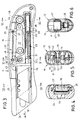
- a knife is generally designated by the reference number 10.
- the knife 10 has two handle shells 11, 12, which are positively joined together and releasably held together by means of a screw connection.
- the grip shell 11 has a threaded blind hole 13 and the grip shell 12 has a screw bolt 15 held in a receiving opening 14.
- the grip shells 11, 12 thus jointly form a grip body 16 with an internal cavity H, which accommodates the main functional parts of the knife 10 which will be described below.
- these main functional parts consist of a pawl 17, a knife blade holder 19 receiving an exchangeable knife blade 18, which is provided with a rear holding extension 20, the latching tooth 21 of which has a Locking surface 22 of the pawl 17 cooperates.
- the forward ejection direction of the knife blade holder 19 into the cutting position of the knife blade 18 is denoted by a.
- the protective position of the knife blade 18 is denoted by b.
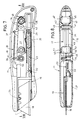
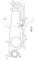
- the pawl 17 also forms an inert mass overall. This has the effect that, in the event of an abrupt, violent movement of the knife 10 in accordance with the arrow designated P in FIG. 2, the pawl 17 initially maintains its initial position while the handle body 16 moves downward relative thereto. This has the consequence that the locking surface 22 is removed from the locking tooth 21 and thus the return spring designed as a tension spring allows the knife blade holder to snap back in direction b in its protective position according to FIG. 3.
- the structural design of the knife 10 can be seen particularly clearly from FIGS. 3-9.
- the knife blade holder 19 is displaceable in a front guide extension 24 of the grip 11 performed, as can be seen in particular from Fig. 4. It is customary to receive the knife blade 18 designed as a trapezoidal blade and to position it by means of driving cams 25 of the knife blade holder 19. Covering the guide channel 26 by means of a locking slide 27 which can be locked with the front guide extension 24 is also common. The locking slide 27 is removed for the purpose of changing the knife blade, then the knife blade 18 is inserted laterally into its position according to FIG. 3 and then the locking slide 27 is again moved into its locked position according to FIG. 4 (cf. also FIG. 1).
- the holding extension 20 connects backwards to the knife blade holder 19.
- the holding extension 20 is firmly connected to the knife blade holder and represents an elongated frame-shaped structure, the rear end of which has an opening 28 over its entire thickness.
- the opening 28 is penetrated by a holding pin 29 fastened in the grip shell 11, which holds the rear eye 30 of the return spring 23, the front spring eye 31 of which is fastened by a holding pin 32 molded onto the holding extension 20.
- the locking spring 33 of the pawl 17 is designed as an elongated soft tension spring.
- the locking spring 33 and the return spring 23 are identical components with the same characteristics.
- the locking pawl 33 extends alongside the locking pawl 17 which forms an elongated one-armed lever.
- the locking pawl 33 engages adjacent to the pivot bearing 34 on the locking pawl 17 by means of a rear spring eye 35.
- the pawl 17 forms a holding pin 37 on a holding arm 36.
- the front spring eye 38 of the locking spring 33 engages around a holding pin 39 fastened to the grip shell 11.
- the rotary bearing 34 of the pawl 17 is designed as follows according to FIG. 8:
- the pawl 17, which is designed as a one-armed lever, is rotatably supported with play in a bearing pin 42 which is inserted in blind holes 40, 41 on both sides of the handle scales 11 and 12.
- the pawl 17 has a T-shaped extension 43 at its free end, which is on both sides on slideways 44, 45 of the handle scales 11 , 12 supports and there is loosely slidably guided.
- the pawl 17 forms at its free end facing away from the pivot bearing 34 a mass accumulation in the form of an interchangeably held circular cylindrical insert 46 (for example made of steel) which is made of a material against a reserve insert 48 held in a receiving opening 47 of the handle scales 11, 12 lower density (e.g. made of plastic) can be replaced.
- an interchangeably held circular cylindrical insert 46 for example made of steel
- a reserve insert 48 held in a receiving opening 47 of the handle scales 11, 12 lower density (e.g. made of plastic)
- the pawl-side receptacle for the insert 46 is a circular cylindrical opening 49, in which the insert 46 is accommodated approximately halfway along the axial length in such a way that it is slightly displaceable in its axial direction. Both end faces 50 of the insert body 46 are loosely supported and slide-guided on the slide ribs 51 on the handle body.
- the insert bodies 46 and 48 have the same dimensions with the above-described different material density.
- the pawl 17 accordingly has a relatively large inert mass, the trigger threshold is low or the response sensitivity is high.
- the trigger threshold is increased, however, if the lightweight reserve insert body 48 made of plastic is used instead of the insert body 46.
Landscapes
- Life Sciences & Earth Sciences (AREA)
- Forests & Forestry (AREA)
- Engineering & Computer Science (AREA)
- Mechanical Engineering (AREA)
- Knives (AREA)
Applications Claiming Priority (2)
| Application Number | Priority Date | Filing Date | Title |
|---|---|---|---|
| DE4200018A DE4200018C1 (es) | 1992-01-02 | 1992-01-02 | |
| DE4200018 | 1992-01-02 |
Publications (2)
| Publication Number | Publication Date |
|---|---|
| EP0549847A1 EP0549847A1 (de) | 1993-07-07 |
| EP0549847B1 true EP0549847B1 (de) | 1994-09-07 |
Family
ID=6449066
Family Applications (1)
| Application Number | Title | Priority Date | Filing Date |
|---|---|---|---|
| EP92106101A Expired - Lifetime EP0549847B1 (de) | 1992-01-02 | 1992-04-09 | Messer mit einer längsverschieblich geführten Messerklingenhalterung |
Country Status (5)
| Country | Link |
|---|---|
| US (1) | US5203085A (es) |
| EP (1) | EP0549847B1 (es) |
| JP (1) | JP2879279B2 (es) |
| DE (2) | DE4200018C1 (es) |
| ES (1) | ES2064131T3 (es) |
Families Citing this family (39)
| Publication number | Priority date | Publication date | Assignee | Title |
|---|---|---|---|---|
| DE4310037C1 (de) * | 1993-03-27 | 1993-12-09 | Beermann Kg Martor Argentax | Messer mit verschiebbarer Messerklinge |
| DE4341360C1 (de) * | 1993-12-04 | 1994-08-18 | Beermann Kg Martor Argentax | Messer mit automatisch wirkender Einzugsvorrichtung der Messerklinge außerhalb ihrer Handhabungsposition |
| JPH11179072A (ja) * | 1997-12-18 | 1999-07-06 | Kds:Kk | カッターナイフ |
| JP3716399B2 (ja) | 1998-03-20 | 2005-11-16 | 株式会社ケイディエス | カッターナイフ |
| AU5330799A (en) * | 1998-07-31 | 2000-02-21 | American Safety Razor Company | Automatic spring retractable utility knife |
| USD434960S (en) * | 1999-05-07 | 2000-12-12 | General Housewares Corporation | Utility knife |
| US6233830B1 (en) | 1999-05-07 | 2001-05-22 | General Housewares Corporation | Utility knife handle |
| FR2810574B1 (fr) * | 2000-06-27 | 2002-10-31 | Mure & Peyrot | Cutter a lame retractable automatiquement |
| US6829827B2 (en) * | 2001-08-06 | 2004-12-14 | Han Chung Tseng | Artistic knife with spare blades |
| US7340836B2 (en) * | 2003-07-29 | 2008-03-11 | Accurate Concepts, Inc. | Hand tool for measuring and cutting |
| US8857064B2 (en) * | 2004-10-15 | 2014-10-14 | Pacific Handy Cutter, Inc. | Safety cutter apparatus |
| US7797836B2 (en) * | 2005-08-02 | 2010-09-21 | The Stanley Works | Compact utility knife |
| US8220160B2 (en) * | 2005-09-16 | 2012-07-17 | Adco Industries-Technologies, L.P. | Box cutter with grip-actuated blade extension |
| DE102005049411B3 (de) * | 2005-10-13 | 2007-03-01 | Martor Kg | Messer |
| US7316070B2 (en) * | 2005-11-15 | 2008-01-08 | Irwin Industrial Tool Company | Self-retracting utility knife |
| DE102005057213B3 (de) * | 2005-11-29 | 2007-03-22 | Martor Kg | Messer |
| JP4851242B2 (ja) * | 2006-06-06 | 2012-01-11 | オルファ株式会社 | セーフティカッターナイフ |
| US7774942B2 (en) * | 2006-10-09 | 2010-08-17 | Pacific Handy Cutter, Inc. | Utility knife |
| US20080172883A1 (en) * | 2007-01-23 | 2008-07-24 | Accurate Concepts, Inc. | Measuring, scoring and cutting tool |
| ATE514533T1 (de) | 2007-04-16 | 2011-07-15 | Adco Ind A Subsidiary Of Dallco Marketing Inc | Schneiden von starrem und halbstarrem material |
| DE102008019441A1 (de) * | 2008-04-17 | 2009-10-22 | Martor Kg | Messer |
| US9676106B2 (en) | 2008-04-29 | 2017-06-13 | Pacific Handy Cutter, Inc. | Safety cutter with guard-actuated blade deployment |
| US8201336B2 (en) | 2008-05-02 | 2012-06-19 | Olympia Tools International, Inc. | Retractable utility knife |
| US8065803B2 (en) * | 2008-06-11 | 2011-11-29 | Taylor Brands, Llc | Cutting tool |
| JP5309360B2 (ja) * | 2008-07-31 | 2013-10-09 | 三菱電機株式会社 | 半導体装置およびその製造方法 |
| US8695221B2 (en) * | 2008-08-21 | 2014-04-15 | Wen Hao | Utility knife with extended travel carriage |
| US8056241B2 (en) * | 2008-10-13 | 2011-11-15 | ADCO Industries—Technologies, L.P. | Utility cutter |
| ES2343560B1 (es) * | 2009-02-02 | 2011-07-19 | Marta Brucart Bonich | Sacacorchos con corta-capsulas telescopico semiautomatico. |
| US20100223793A1 (en) * | 2009-03-04 | 2010-09-09 | The Stanley Works | Utility knife |
| US8307556B2 (en) | 2009-06-19 | 2012-11-13 | ADCO Industries—Technologies, L.P. | Utility cutter |
| TWM394220U (en) * | 2010-03-24 | 2010-12-11 | jun-feng He | Safety utility knife |
| DE102010019571B4 (de) * | 2010-05-05 | 2020-05-20 | Martor Kg | Messer |
| US9289904B2 (en) * | 2011-11-14 | 2016-03-22 | Grant Woodrow Hawk | Lock optional, spring assisted folding knife |
| US8782909B1 (en) | 2013-02-12 | 2014-07-22 | ADCO Industries—Technologies, L.P. | Utility cutter |
| GB2538280A (en) * | 2015-05-14 | 2016-11-16 | Hacksaw & Knife Manufactory Co Ltd | Box cutter structure |
| BR112017026981A2 (pt) * | 2015-06-17 | 2018-09-04 | Starrett Ind E Comercio Ltda | aperfeiçoamentos introduzidos em estilete compacto de segurança |
| TWM511938U (zh) * | 2015-08-21 | 2015-11-11 | Kantas Products Co Ltd | 能在刀柄同側面操控刀刃彈出及收合之彈簧輔助式刀具 |
| KR200486207Y1 (ko) * | 2016-05-09 | 2018-04-16 | 대우조선해양 주식회사 | 케이블 피복제거용 전공칼 |
| KR200488029Y1 (ko) * | 2016-11-30 | 2018-12-05 | 삼성중공업 주식회사 | 전공칼 |
Family Cites Families (7)
| Publication number | Priority date | Publication date | Assignee | Title |
|---|---|---|---|---|
| US1623906A (en) * | 1926-09-25 | 1927-04-05 | Desmond B Brooks | Novelty |
| GB649406A (en) * | 1948-09-14 | 1951-01-24 | Dunlop Rubber Co | An improved safety cutting knife |
| US3999290A (en) * | 1976-03-15 | 1976-12-28 | Wood Jess W | Safety knife |
| DE2736395C2 (de) * | 1977-08-12 | 1979-07-12 | Martor-Argentax E.H. Beermann Kg, 5650 Solingen | Messer mit einer längsverschieblich geführten zugfederbelasteten Messerklingenhalterung |
| GB8432145D0 (en) * | 1984-12-20 | 1985-01-30 | Shirley Inst | Knife |
| GB2192358B (en) * | 1986-07-08 | 1989-12-20 | Shirley Inst The | Knife |
| NL8901907A (nl) * | 1989-07-24 | 1991-02-18 | Apex Rb Design | Kinderveilig hobby mes. |
-
1992
- 1992-01-02 DE DE4200018A patent/DE4200018C1/de not_active Expired - Lifetime
- 1992-04-09 ES ES92106101T patent/ES2064131T3/es not_active Expired - Lifetime
- 1992-04-09 EP EP92106101A patent/EP0549847B1/de not_active Expired - Lifetime
- 1992-04-09 DE DE59200476T patent/DE59200476D1/de not_active Expired - Lifetime
- 1992-04-30 US US07/876,235 patent/US5203085A/en not_active Expired - Lifetime
- 1992-06-05 JP JP4187277A patent/JP2879279B2/ja not_active Expired - Fee Related
Also Published As
| Publication number | Publication date |
|---|---|
| EP0549847A1 (de) | 1993-07-07 |
| JPH05212161A (ja) | 1993-08-24 |
| DE59200476D1 (de) | 1994-10-13 |
| US5203085A (en) | 1993-04-20 |
| ES2064131T3 (es) | 1995-01-16 |
| JP2879279B2 (ja) | 1999-04-05 |
| DE4200018C1 (es) | 1992-11-05 |
Similar Documents
| Publication | Publication Date | Title |
|---|---|---|
| EP0549847B1 (de) | Messer mit einer längsverschieblich geführten Messerklingenhalterung | |
| DE2954489C2 (de) | Sicherheitsschneidvorrichtung | |
| DE69401640T2 (de) | Haltevorrichtung mit Handgriff für Aerosolbehälter | |
| DE69006009T2 (de) | Nassrasierer mit einer gleitenden Stütze für die Klingeneinheit. | |
| DE69718447T2 (de) | Zahnbürste mit einem entgegen einer federkraft beweglichen bürstenhalter | |
| EP0729811B1 (de) | Kartonmesser | |
| EP0099444B1 (de) | Vorrichtung zur Bildung eines Schlüsselbundes | |
| EP2716420B1 (de) | Messer | |
| DE102009015276B4 (de) | Haarschneidemaschine mit auswechselbarem Schneidsatz und Schnittlängen-Verstelleinrichtung | |
| EP1340599A1 (de) | Messer | |
| EP0865242B1 (de) | Handstopfvorrichtung für zigarettenhülsen, insbesondere zigarettenfilterhülsen mit hinsichtlich der länge variierbarer tabakpresskammer | |
| DE202004004422U1 (de) | Messer mit austauschbarer Klinge | |
| EP0357705B1 (de) | Verschlusseinrichtung für den kinnriemen eines motorradschutzhelms | |
| DE2736395B1 (de) | Messer mit einer laengsverschieblich gefuehrten zugfederbelasteten Messerklingenhalterung | |
| DE2310573A1 (de) | Immer spitzer druckstift | |
| DE4025382A1 (de) | Verbessertes schloss mit zuschlagwirkung mit auswurffeder | |
| DE69003778T2 (de) | Schneidklingen-Schärfgerät. | |
| DE3525242C2 (es) | ||
| EP2703133B1 (de) | Messer | |
| EP0955133B1 (de) | Verlegemesser | |
| DE2914088C2 (de) | Sperrvorrichtung für einen von Hand betätigbaren Schalthebel | |
| DE2506925A1 (de) | Schwenkbares messer | |
| DE3046093A1 (de) | Schreibgeraet mit in einer vertiefung des gehaeuses versenkt angeordnetem clip | |
| DE9014307U1 (de) | Haarentfernungsapparat | |
| EP0317954B1 (de) | Wechselklingenmesser |
Legal Events
| Date | Code | Title | Description |
|---|---|---|---|
| PUAI | Public reference made under article 153(3) epc to a published international application that has entered the european phase |
Free format text: ORIGINAL CODE: 0009012 |
|
| AK | Designated contracting states |
Kind code of ref document: A1 Designated state(s): BE DE ES FR GB IT NL PT |
|
| 17P | Request for examination filed |
Effective date: 19930522 |
|
| 17Q | First examination report despatched |
Effective date: 19930929 |
|
| ITF | It: translation for a ep patent filed | ||
| GRAA | (expected) grant |
Free format text: ORIGINAL CODE: 0009210 |
|
| AK | Designated contracting states |
Kind code of ref document: B1 Designated state(s): BE DE ES FR GB IT NL PT |
|
| GBT | Gb: translation of ep patent filed (gb section 77(6)(a)/1977) |
Effective date: 19940913 |
|
| REF | Corresponds to: |
Ref document number: 59200476 Country of ref document: DE Date of ref document: 19941013 |
|
| ET | Fr: translation filed | ||
| REG | Reference to a national code |
Ref country code: ES Ref legal event code: FG2A Ref document number: 2064131 Country of ref document: ES Kind code of ref document: T3 |
|
| SC4A | Pt: translation is available |
Free format text: 940908 AVAILABILITY OF NATIONAL TRANSLATION |
|
| PGFP | Annual fee paid to national office [announced via postgrant information from national office to epo] |
Ref country code: PT Payment date: 19950321 Year of fee payment: 4 |
|
| PGFP | Annual fee paid to national office [announced via postgrant information from national office to epo] |
Ref country code: ES Payment date: 19950425 Year of fee payment: 4 |
|
| PLBE | No opposition filed within time limit |
Free format text: ORIGINAL CODE: 0009261 |
|
| STAA | Information on the status of an ep patent application or granted ep patent |
Free format text: STATUS: NO OPPOSITION FILED WITHIN TIME LIMIT |
|
| 26N | No opposition filed | ||
| PG25 | Lapsed in a contracting state [announced via postgrant information from national office to epo] |
Ref country code: ES Free format text: LAPSE BECAUSE OF NON-PAYMENT OF DUE FEES Effective date: 19960410 |
|
| PGFP | Annual fee paid to national office [announced via postgrant information from national office to epo] |
Ref country code: BE Payment date: 19960424 Year of fee payment: 5 |
|
| PG25 | Lapsed in a contracting state [announced via postgrant information from national office to epo] |
Ref country code: PT Effective date: 19961031 |
|
| REG | Reference to a national code |
Ref country code: PT Ref legal event code: MM4A Free format text: LAPSE DUE TO NON-PAYMENT OF FEES Effective date: 19961031 |
|
| PG25 | Lapsed in a contracting state [announced via postgrant information from national office to epo] |
Ref country code: BE Effective date: 19970430 |
|
| PGFP | Annual fee paid to national office [announced via postgrant information from national office to epo] |
Ref country code: NL Payment date: 19970430 Year of fee payment: 6 |
|
| BERE | Be: lapsed |
Owner name: MARTOR-ARGENTAX E.H. BEERMANN K.G. Effective date: 19970430 |
|
| PG25 | Lapsed in a contracting state [announced via postgrant information from national office to epo] |
Ref country code: NL Free format text: LAPSE BECAUSE OF NON-PAYMENT OF DUE FEES Effective date: 19981101 |
|
| NLV4 | Nl: lapsed or anulled due to non-payment of the annual fee |
Effective date: 19981101 |
|
| REG | Reference to a national code |
Ref country code: ES Ref legal event code: FD2A Effective date: 19990201 |
|
| REG | Reference to a national code |
Ref country code: GB Ref legal event code: IF02 |
|
| REG | Reference to a national code |
Ref country code: FR Ref legal event code: CD |
|
| PG25 | Lapsed in a contracting state [announced via postgrant information from national office to epo] |
Ref country code: IT Free format text: LAPSE BECAUSE OF NON-PAYMENT OF DUE FEES;WARNING: LAPSES OF ITALIAN PATENTS WITH EFFECTIVE DATE BEFORE 2007 MAY HAVE OCCURRED AT ANY TIME BEFORE 2007. THE CORRECT EFFECTIVE DATE MAY BE DIFFERENT FROM THE ONE RECORDED. Effective date: 20050409 |
|
| PGFP | Annual fee paid to national office [announced via postgrant information from national office to epo] |
Ref country code: GB Payment date: 20100326 Year of fee payment: 19 |
|
| PGFP | Annual fee paid to national office [announced via postgrant information from national office to epo] |
Ref country code: FR Payment date: 20100519 Year of fee payment: 19 |
|
| PGFP | Annual fee paid to national office [announced via postgrant information from national office to epo] |
Ref country code: DE Payment date: 20100129 Year of fee payment: 19 |
|
| GBPC | Gb: european patent ceased through non-payment of renewal fee |
Effective date: 20110409 |
|
| REG | Reference to a national code |
Ref country code: FR Ref legal event code: ST Effective date: 20111230 |
|
| PG25 | Lapsed in a contracting state [announced via postgrant information from national office to epo] |
Ref country code: DE Free format text: LAPSE BECAUSE OF NON-PAYMENT OF DUE FEES Effective date: 20111101 Ref country code: FR Free format text: LAPSE BECAUSE OF NON-PAYMENT OF DUE FEES Effective date: 20110502 |
|
| REG | Reference to a national code |
Ref country code: DE Ref legal event code: R119 Ref document number: 59200476 Country of ref document: DE Effective date: 20111101 |
|
| PG25 | Lapsed in a contracting state [announced via postgrant information from national office to epo] |
Ref country code: GB Free format text: LAPSE BECAUSE OF NON-PAYMENT OF DUE FEES Effective date: 20110409 |