EP0549562B1 - Verfahren und Vorrichtung zur Aufzeichnung und Wiedergabe von Information - Google Patents
Verfahren und Vorrichtung zur Aufzeichnung und Wiedergabe von Information Download PDFInfo
- Publication number
- EP0549562B1 EP0549562B1 EP93100423A EP93100423A EP0549562B1 EP 0549562 B1 EP0549562 B1 EP 0549562B1 EP 93100423 A EP93100423 A EP 93100423A EP 93100423 A EP93100423 A EP 93100423A EP 0549562 B1 EP0549562 B1 EP 0549562B1
- Authority
- EP
- European Patent Office
- Prior art keywords
- level
- recording
- power
- information
- medium
- Prior art date
- Legal status (The legal status is an assumption and is not a legal conclusion. Google has not performed a legal analysis and makes no representation as to the accuracy of the status listed.)
- Expired - Lifetime
Links
Images


Classifications
-
- G—PHYSICS
- G11—INFORMATION STORAGE
- G11B—INFORMATION STORAGE BASED ON RELATIVE MOVEMENT BETWEEN RECORD CARRIER AND TRANSDUCER
- G11B7/00—Recording or reproducing by optical means, e.g. recording using a thermal beam of optical radiation by modifying optical properties or the physical structure, reproducing using an optical beam at lower power by sensing optical properties; Record carriers therefor
- G11B7/004—Recording, reproducing or erasing methods; Read, write or erase circuits therefor
- G11B7/006—Overwriting
- G11B7/0062—Overwriting strategies, e.g. recording pulse sequences with erasing level used for phase-change media
-
- G—PHYSICS
- G11—INFORMATION STORAGE
- G11B—INFORMATION STORAGE BASED ON RELATIVE MOVEMENT BETWEEN RECORD CARRIER AND TRANSDUCER
- G11B11/00—Recording on or reproducing from the same record carrier wherein for these two operations the methods are covered by different main groups of groups G11B3/00 - G11B7/00 or by different subgroups of group G11B9/00; Record carriers therefor
- G11B11/10—Recording on or reproducing from the same record carrier wherein for these two operations the methods are covered by different main groups of groups G11B3/00 - G11B7/00 or by different subgroups of group G11B9/00; Record carriers therefor using recording by magnetic means or other means for magnetisation or demagnetisation of a record carrier, e.g. light induced spin magnetisation; Demagnetisation by thermal or stress means in the presence or not of an orienting magnetic field
- G11B11/105—Recording on or reproducing from the same record carrier wherein for these two operations the methods are covered by different main groups of groups G11B3/00 - G11B7/00 or by different subgroups of group G11B9/00; Record carriers therefor using recording by magnetic means or other means for magnetisation or demagnetisation of a record carrier, e.g. light induced spin magnetisation; Demagnetisation by thermal or stress means in the presence or not of an orienting magnetic field using a beam of light or a magnetic field for recording by change of magnetisation and a beam of light for reproducing, i.e. magneto-optical, e.g. light-induced thermomagnetic recording, spin magnetisation recording, Kerr or Faraday effect reproducing
- G11B11/10502—Recording on or reproducing from the same record carrier wherein for these two operations the methods are covered by different main groups of groups G11B3/00 - G11B7/00 or by different subgroups of group G11B9/00; Record carriers therefor using recording by magnetic means or other means for magnetisation or demagnetisation of a record carrier, e.g. light induced spin magnetisation; Demagnetisation by thermal or stress means in the presence or not of an orienting magnetic field using a beam of light or a magnetic field for recording by change of magnetisation and a beam of light for reproducing, i.e. magneto-optical, e.g. light-induced thermomagnetic recording, spin magnetisation recording, Kerr or Faraday effect reproducing characterised by the transducing operation to be executed
- G11B11/10504—Recording
- G11B11/10506—Recording by modulating only the light beam of the transducer
-
- G—PHYSICS
- G11—INFORMATION STORAGE
- G11B—INFORMATION STORAGE BASED ON RELATIVE MOVEMENT BETWEEN RECORD CARRIER AND TRANSDUCER
- G11B11/00—Recording on or reproducing from the same record carrier wherein for these two operations the methods are covered by different main groups of groups G11B3/00 - G11B7/00 or by different subgroups of group G11B9/00; Record carriers therefor
- G11B11/10—Recording on or reproducing from the same record carrier wherein for these two operations the methods are covered by different main groups of groups G11B3/00 - G11B7/00 or by different subgroups of group G11B9/00; Record carriers therefor using recording by magnetic means or other means for magnetisation or demagnetisation of a record carrier, e.g. light induced spin magnetisation; Demagnetisation by thermal or stress means in the presence or not of an orienting magnetic field
- G11B11/105—Recording on or reproducing from the same record carrier wherein for these two operations the methods are covered by different main groups of groups G11B3/00 - G11B7/00 or by different subgroups of group G11B9/00; Record carriers therefor using recording by magnetic means or other means for magnetisation or demagnetisation of a record carrier, e.g. light induced spin magnetisation; Demagnetisation by thermal or stress means in the presence or not of an orienting magnetic field using a beam of light or a magnetic field for recording by change of magnetisation and a beam of light for reproducing, i.e. magneto-optical, e.g. light-induced thermomagnetic recording, spin magnetisation recording, Kerr or Faraday effect reproducing
- G11B11/10502—Recording on or reproducing from the same record carrier wherein for these two operations the methods are covered by different main groups of groups G11B3/00 - G11B7/00 or by different subgroups of group G11B9/00; Record carriers therefor using recording by magnetic means or other means for magnetisation or demagnetisation of a record carrier, e.g. light induced spin magnetisation; Demagnetisation by thermal or stress means in the presence or not of an orienting magnetic field using a beam of light or a magnetic field for recording by change of magnetisation and a beam of light for reproducing, i.e. magneto-optical, e.g. light-induced thermomagnetic recording, spin magnetisation recording, Kerr or Faraday effect reproducing characterised by the transducing operation to be executed
- G11B11/10517—Overwriting or erasing
- G11B11/10519—Direct overwriting, i.e. performing erasing and recording using the same transducing means
- G11B11/10521—Direct overwriting, i.e. performing erasing and recording using the same transducing means using a single light spot
-
- G—PHYSICS
- G11—INFORMATION STORAGE
- G11B—INFORMATION STORAGE BASED ON RELATIVE MOVEMENT BETWEEN RECORD CARRIER AND TRANSDUCER
- G11B11/00—Recording on or reproducing from the same record carrier wherein for these two operations the methods are covered by different main groups of groups G11B3/00 - G11B7/00 or by different subgroups of group G11B9/00; Record carriers therefor
- G11B11/10—Recording on or reproducing from the same record carrier wherein for these two operations the methods are covered by different main groups of groups G11B3/00 - G11B7/00 or by different subgroups of group G11B9/00; Record carriers therefor using recording by magnetic means or other means for magnetisation or demagnetisation of a record carrier, e.g. light induced spin magnetisation; Demagnetisation by thermal or stress means in the presence or not of an orienting magnetic field
- G11B11/11—Recording on or reproducing from the same record carrier wherein for these two operations the methods are covered by different main groups of groups G11B3/00 - G11B7/00 or by different subgroups of group G11B9/00; Record carriers therefor using recording by magnetic means or other means for magnetisation or demagnetisation of a record carrier, e.g. light induced spin magnetisation; Demagnetisation by thermal or stress means in the presence or not of an orienting magnetic field using a beam, e.g. of electrons or X-rays other than a beam of light or a magnetic field for recording
-
- G—PHYSICS
- G11—INFORMATION STORAGE
- G11B—INFORMATION STORAGE BASED ON RELATIVE MOVEMENT BETWEEN RECORD CARRIER AND TRANSDUCER
- G11B7/00—Recording or reproducing by optical means, e.g. recording using a thermal beam of optical radiation by modifying optical properties or the physical structure, reproducing using an optical beam at lower power by sensing optical properties; Record carriers therefor
- G11B7/004—Recording, reproducing or erasing methods; Read, write or erase circuits therefor
- G11B7/0055—Erasing
- G11B7/00557—Erasing involving phase-change media
-
- G—PHYSICS
- G11—INFORMATION STORAGE
- G11B—INFORMATION STORAGE BASED ON RELATIVE MOVEMENT BETWEEN RECORD CARRIER AND TRANSDUCER
- G11B7/00—Recording or reproducing by optical means, e.g. recording using a thermal beam of optical radiation by modifying optical properties or the physical structure, reproducing using an optical beam at lower power by sensing optical properties; Record carriers therefor
- G11B7/004—Recording, reproducing or erasing methods; Read, write or erase circuits therefor
- G11B7/006—Overwriting
-
- G—PHYSICS
- G11—INFORMATION STORAGE
- G11B—INFORMATION STORAGE BASED ON RELATIVE MOVEMENT BETWEEN RECORD CARRIER AND TRANSDUCER
- G11B7/00—Recording or reproducing by optical means, e.g. recording using a thermal beam of optical radiation by modifying optical properties or the physical structure, reproducing using an optical beam at lower power by sensing optical properties; Record carriers therefor
- G11B7/24—Record carriers characterised by shape, structure or physical properties, or by the selection of the material
- G11B7/241—Record carriers characterised by shape, structure or physical properties, or by the selection of the material characterised by the selection of the material
- G11B7/242—Record carriers characterised by shape, structure or physical properties, or by the selection of the material characterised by the selection of the material of recording layers
- G11B7/243—Record carriers characterised by shape, structure or physical properties, or by the selection of the material characterised by the selection of the material of recording layers comprising inorganic materials only, e.g. ablative layers
-
- G—PHYSICS
- G11—INFORMATION STORAGE
- G11B—INFORMATION STORAGE BASED ON RELATIVE MOVEMENT BETWEEN RECORD CARRIER AND TRANSDUCER
- G11B9/00—Recording or reproducing using a method not covered by one of the main groups G11B3/00 - G11B7/00; Record carriers therefor
-
- G—PHYSICS
- G11—INFORMATION STORAGE
- G11B—INFORMATION STORAGE BASED ON RELATIVE MOVEMENT BETWEEN RECORD CARRIER AND TRANSDUCER
- G11B9/00—Recording or reproducing using a method not covered by one of the main groups G11B3/00 - G11B7/00; Record carriers therefor
- G11B9/10—Recording or reproducing using a method not covered by one of the main groups G11B3/00 - G11B7/00; Record carriers therefor using electron beam; Record carriers therefor
-
- G—PHYSICS
- G11—INFORMATION STORAGE
- G11B—INFORMATION STORAGE BASED ON RELATIVE MOVEMENT BETWEEN RECORD CARRIER AND TRANSDUCER
- G11B7/00—Recording or reproducing by optical means, e.g. recording using a thermal beam of optical radiation by modifying optical properties or the physical structure, reproducing using an optical beam at lower power by sensing optical properties; Record carriers therefor
- G11B7/24—Record carriers characterised by shape, structure or physical properties, or by the selection of the material
- G11B7/241—Record carriers characterised by shape, structure or physical properties, or by the selection of the material characterised by the selection of the material
- G11B7/242—Record carriers characterised by shape, structure or physical properties, or by the selection of the material characterised by the selection of the material of recording layers
- G11B7/243—Record carriers characterised by shape, structure or physical properties, or by the selection of the material characterised by the selection of the material of recording layers comprising inorganic materials only, e.g. ablative layers
- G11B2007/24302—Metals or metalloids
- G11B2007/24304—Metals or metalloids group 2 or 12 elements (e.g. Be, Ca, Mg, Zn, Cd)
-
- G—PHYSICS
- G11—INFORMATION STORAGE
- G11B—INFORMATION STORAGE BASED ON RELATIVE MOVEMENT BETWEEN RECORD CARRIER AND TRANSDUCER
- G11B7/00—Recording or reproducing by optical means, e.g. recording using a thermal beam of optical radiation by modifying optical properties or the physical structure, reproducing using an optical beam at lower power by sensing optical properties; Record carriers therefor
- G11B7/24—Record carriers characterised by shape, structure or physical properties, or by the selection of the material
- G11B7/241—Record carriers characterised by shape, structure or physical properties, or by the selection of the material characterised by the selection of the material
- G11B7/242—Record carriers characterised by shape, structure or physical properties, or by the selection of the material characterised by the selection of the material of recording layers
- G11B7/243—Record carriers characterised by shape, structure or physical properties, or by the selection of the material characterised by the selection of the material of recording layers comprising inorganic materials only, e.g. ablative layers
- G11B2007/24302—Metals or metalloids
- G11B2007/2431—Metals or metalloids group 13 elements (B, Al, Ga, In)
-
- G—PHYSICS
- G11—INFORMATION STORAGE
- G11B—INFORMATION STORAGE BASED ON RELATIVE MOVEMENT BETWEEN RECORD CARRIER AND TRANSDUCER
- G11B7/00—Recording or reproducing by optical means, e.g. recording using a thermal beam of optical radiation by modifying optical properties or the physical structure, reproducing using an optical beam at lower power by sensing optical properties; Record carriers therefor
- G11B7/24—Record carriers characterised by shape, structure or physical properties, or by the selection of the material
- G11B7/241—Record carriers characterised by shape, structure or physical properties, or by the selection of the material characterised by the selection of the material
- G11B7/242—Record carriers characterised by shape, structure or physical properties, or by the selection of the material characterised by the selection of the material of recording layers
- G11B7/243—Record carriers characterised by shape, structure or physical properties, or by the selection of the material characterised by the selection of the material of recording layers comprising inorganic materials only, e.g. ablative layers
- G11B2007/24302—Metals or metalloids
- G11B2007/24312—Metals or metalloids group 14 elements (e.g. Si, Ge, Sn)
-
- G—PHYSICS
- G11—INFORMATION STORAGE
- G11B—INFORMATION STORAGE BASED ON RELATIVE MOVEMENT BETWEEN RECORD CARRIER AND TRANSDUCER
- G11B7/00—Recording or reproducing by optical means, e.g. recording using a thermal beam of optical radiation by modifying optical properties or the physical structure, reproducing using an optical beam at lower power by sensing optical properties; Record carriers therefor
- G11B7/24—Record carriers characterised by shape, structure or physical properties, or by the selection of the material
- G11B7/241—Record carriers characterised by shape, structure or physical properties, or by the selection of the material characterised by the selection of the material
- G11B7/242—Record carriers characterised by shape, structure or physical properties, or by the selection of the material characterised by the selection of the material of recording layers
- G11B7/243—Record carriers characterised by shape, structure or physical properties, or by the selection of the material characterised by the selection of the material of recording layers comprising inorganic materials only, e.g. ablative layers
- G11B2007/24302—Metals or metalloids
- G11B2007/24314—Metals or metalloids group 15 elements (e.g. Sb, Bi)
-
- G—PHYSICS
- G11—INFORMATION STORAGE
- G11B—INFORMATION STORAGE BASED ON RELATIVE MOVEMENT BETWEEN RECORD CARRIER AND TRANSDUCER
- G11B7/00—Recording or reproducing by optical means, e.g. recording using a thermal beam of optical radiation by modifying optical properties or the physical structure, reproducing using an optical beam at lower power by sensing optical properties; Record carriers therefor
- G11B7/24—Record carriers characterised by shape, structure or physical properties, or by the selection of the material
- G11B7/241—Record carriers characterised by shape, structure or physical properties, or by the selection of the material characterised by the selection of the material
- G11B7/242—Record carriers characterised by shape, structure or physical properties, or by the selection of the material characterised by the selection of the material of recording layers
- G11B7/243—Record carriers characterised by shape, structure or physical properties, or by the selection of the material characterised by the selection of the material of recording layers comprising inorganic materials only, e.g. ablative layers
- G11B2007/24302—Metals or metalloids
- G11B2007/24316—Metals or metalloids group 16 elements (i.e. chalcogenides, Se, Te)
-
- G—PHYSICS
- G11—INFORMATION STORAGE
- G11B—INFORMATION STORAGE BASED ON RELATIVE MOVEMENT BETWEEN RECORD CARRIER AND TRANSDUCER
- G11B7/00—Recording or reproducing by optical means, e.g. recording using a thermal beam of optical radiation by modifying optical properties or the physical structure, reproducing using an optical beam at lower power by sensing optical properties; Record carriers therefor
- G11B7/24—Record carriers characterised by shape, structure or physical properties, or by the selection of the material
- G11B7/241—Record carriers characterised by shape, structure or physical properties, or by the selection of the material characterised by the selection of the material
- G11B7/242—Record carriers characterised by shape, structure or physical properties, or by the selection of the material characterised by the selection of the material of recording layers
- G11B7/243—Record carriers characterised by shape, structure or physical properties, or by the selection of the material characterised by the selection of the material of recording layers comprising inorganic materials only, e.g. ablative layers
- G11B2007/24318—Non-metallic elements
- G11B2007/24324—Sulfur
-
- G—PHYSICS
- G11—INFORMATION STORAGE
- G11B—INFORMATION STORAGE BASED ON RELATIVE MOVEMENT BETWEEN RECORD CARRIER AND TRANSDUCER
- G11B7/00—Recording or reproducing by optical means, e.g. recording using a thermal beam of optical radiation by modifying optical properties or the physical structure, reproducing using an optical beam at lower power by sensing optical properties; Record carriers therefor
- G11B7/24—Record carriers characterised by shape, structure or physical properties, or by the selection of the material
- G11B7/241—Record carriers characterised by shape, structure or physical properties, or by the selection of the material characterised by the selection of the material
- G11B7/252—Record carriers characterised by shape, structure or physical properties, or by the selection of the material characterised by the selection of the material of layers other than recording layers
- G11B7/257—Record carriers characterised by shape, structure or physical properties, or by the selection of the material characterised by the selection of the material of layers other than recording layers of layers having properties involved in recording or reproduction, e.g. optical interference layers or sensitising layers or dielectric layers, which are protecting the recording layers
- G11B7/2572—Record carriers characterised by shape, structure or physical properties, or by the selection of the material characterised by the selection of the material of layers other than recording layers of layers having properties involved in recording or reproduction, e.g. optical interference layers or sensitising layers or dielectric layers, which are protecting the recording layers consisting essentially of organic materials
-
- G—PHYSICS
- G11—INFORMATION STORAGE
- G11B—INFORMATION STORAGE BASED ON RELATIVE MOVEMENT BETWEEN RECORD CARRIER AND TRANSDUCER
- G11B7/00—Recording or reproducing by optical means, e.g. recording using a thermal beam of optical radiation by modifying optical properties or the physical structure, reproducing using an optical beam at lower power by sensing optical properties; Record carriers therefor
- G11B7/24—Record carriers characterised by shape, structure or physical properties, or by the selection of the material
- G11B7/241—Record carriers characterised by shape, structure or physical properties, or by the selection of the material characterised by the selection of the material
- G11B7/252—Record carriers characterised by shape, structure or physical properties, or by the selection of the material characterised by the selection of the material of layers other than recording layers
- G11B7/257—Record carriers characterised by shape, structure or physical properties, or by the selection of the material characterised by the selection of the material of layers other than recording layers of layers having properties involved in recording or reproduction, e.g. optical interference layers or sensitising layers or dielectric layers, which are protecting the recording layers
- G11B7/2578—Record carriers characterised by shape, structure or physical properties, or by the selection of the material characterised by the selection of the material of layers other than recording layers of layers having properties involved in recording or reproduction, e.g. optical interference layers or sensitising layers or dielectric layers, which are protecting the recording layers consisting essentially of inorganic materials
Definitions
- the present invention relates to a method for recording, reproducing and erasing information by irradiating an energy, beam such as a light or electron beam onto an information recording medium, and more particularly to a method for recording, reproducing and erasing information by a single beam spot by using a phase change and an information recording medium which is effective for use in the above method.
- JP-A-59-71140 A prior art method for recording, reproducing and erasing information in a phase change type optical disk is shown in JP-A-59-71140 in which recording is done by irradiating a small circular light spot formed by fully focusing a light beam spot for a short time period to render a recording film to a complete amorphous state by quick heating and cooling, and erasing is done by irradiating an elliptical light spot extending along a track to keep the recording material at a crystallization temperature for a relatively long time so that the amorphous state recorded area is returned to a complete crystalline state.
- two different beam spots are used for recording and reproducing.
- JP-A-56-148740 A second prior art method is disclosed in JP-A-56-148740 in which a single light beam spot is used to erase recorded information in one or a plurality of revolutions of a disk medium and record information in the next revolution.
- JP-A-56-145530 A third prior art method is disclosed in JP-A-56-145530 in which a light which is intensity modulated between at least two power levels is irradiated to simultaneously record and erase information.
- the above problems are resolved but it is necessary to completely crystallize the recording film prior to recording, and tracking at a reproduction power level, automatic focusing and track or sector address confirmation prior to recording are not effected. Further, since an initial power level is not always an erase power level, a leading portion of the previously written information will not be updated if a start position of updating is deviated.
- JP-B-47-26897 which also describes various thin films such as Te-Ge, As-Te-Ge and Te-O.
- JP-B-54-41902 discloses various compositions such as Ge 10 Tl 5 Sb 5 Se 70 and Ge 20 Bi 10 Se 70 .
- JP-A-57-24039 discloses thin films of Sb 25 Te 12 5 Se 62.5 , Cd 14 Te 14 Se 72 , Bi 2 Se 3 , Sb 2 Se 3 , In 20 Te 20 Se 60 , Bi 25 Te 12.5 Se 62.5 , CuSe and Te 33 Se 67 .
- the JP-A-56-145 530 discloses the method for rewriting information described in the preamble of claim 1. This method includes the use of a beam energy for rewriting having two different power levels.
- the above object is achieved by the method defined in claim 1.
- the power of an energy beam such as a light, electron or ion beam is changed between power levels capable of causing a state change (phase change) during recording of information. More specifically, information may be updated (erasing and rewriting) during one passage of the spot on a recording film.
- the reproduction level of the updating light spot may be used only for tracking and auto-focusing.
- the power may be rendered zero from the reproduction level for a very short time without affect to the tracking and auto-focusing, and such is within the scope of the present invention.
- the method of recording, reproducing and erasing information in accordance with the present invention enables so-called overwriting by which new information is recorded while an existing record is erased.
- information may be updated (erased and rewritten) while an energy beam spot scans a recording film in one run.
- a disk is rotated while a recording track (between tracking grooves) is rendered almost amorphous and an area between tracks is rendered crystalline, and information is reproduced by a single laser or electron beam spot.
- the beam spot reaches a rewrite position, the power is changed between a plurality of power levels other than a reproduce power level (continuous oscillation) (usually between a record level higher than the reproduce power level and an erase level) to rewrite information.
- the record level and erase level are defined as laser powers which are optimum for recording and erasing, respectively, to continuously maintain the power.
- the laser power may be changed by superimposing to a waveform whose power pulsively rises from a reproduce level to a record level in a conventional write-once optical disk, a waveform whose power rises from a power level which is between 0 level to the reproduce level in a rewrite area to an erase level (that is, producing a higher one of those powers).
- the rewritable optical disk and the write-once optical disk may be recorded and reproduced by one apparatus.
- the power is raised from the reproduce power level to the erase power level and then the power is pulsively raised from the erase level.
- the problem encountered in the third prior art is resolved.
- the pulsive power reduction for erasing it is preferable to significantly reduce the power in an initial stage, so that a temperature suitable for erasing is quickly attained.
- the pulsive power rise for recording it is preferable to significantly raise the power in an initial stage to raise the power above the record power level and then lower the power to the record power level.
- the beam spot on the disk medium is preferably enlarged by utilizing wavelength change due to mode change by laser power control, reduction of high frequency superposition or control of amount of return light, or color astigmatism of a lens, or by changing a light path length by utilizing a beam deflector to defocus the beam spot, so that the irradiation time is gained and imperfection of erase information is prevented.
- Which of two or more states of the recording film are to be selected as the record state and erase state is arbitrary.
- a low reflection state by a high power laser beam irradiation may be selected as the record state or it may be selected as the erase state. Since it is preferable to shorten the irradiation time of the high power laser beam in order to avoid deformation of the recording film, it is preferable to select the high power laser beam irradiation state as the record state.
- the generation of noise due to ununiform crystallization of an area between tracks when the information is repeatedly rewritten can be prevented by previously rendering the area between the record tracks the crystalline state.
- a point on the disk may not be completely crystallized because of insufficient irradiation time even if the beam of crystallization energy level is irradiated. If the beam of the crystallization level is again irradiated in the rewriting mode, the crystallization proceeds and the reflection coefficient of the crystallized area is not uniform but varies from point to point.
- a comparator level it is preferable to set a comparator level to a voltage corresponding to a reflection coefficient of a point of the crystallized area which is closest to a reflection coefficient of a point of other state (near-amorphous state), or a reflection coefficient which is intermediate of said reflection coefficient and a reflection coefficient of a point of the near-amorphous state (if it has a range, a reflection coefficient of a point closest to the crystalline state) so that a signal voltage of the crystallization level is clipped to such a level.
- the comparator level is set to an intermediate voltage between a voltage corresponding to the reflection coefficient of the crystalline state and a voltage corresponding to a reflection coefficient of the near-amorphous state, or a voltage closer to the voltage corresponding to the reflection coefficient of the near-amorphous state, the reproduction of information is assured. If the comparator level is set to a voltage between the above intermediate voltage and a voltage of the crystalline state closest to the intermediate voltage, the original waveform can be exactly reproduced. Other waveform shaping devices may be used to shape the waveform.
- the substrate When information is recorded by the phase change, it is one approach to previously crystalize the entire surface of the recording film.
- the substrate When the substrate is made of an organic material, the substrate should not be heated to a high temperature and another crystalization method should be employed.
- irradiation of a laser beam focused to a spot diameter of less than 2 ⁇ m, irradiation of UV ray and heating, irradiation of light from a flash lamp such as xenon lamp or Hg-vapor lamp, irradiation of light by a large light spot from a high power gas laser, or irradiation of a laser beam and heating may be preferably used.
- the light spot diameter (half-value width) is preferably between 5 ⁇ m and 5 mm in order to attain a high initial crystalization efficiency.
- Information may also be recorded by crystallizing the amorphous recording thin films or by changing crystal grain sizes in polycrystalline thin film.
- an optical property may be changed by any change of atom arrangement (widely interpreted phase change).
- a change between polycrystalline states of different average grain sizes of crystals may be utilized for the recording.
- the recording member may be used not only in a disk form but also in other forms such as tape and card. It is effective to both the rewriting by a single light beam spot and the rewriting by a multi-light beam spot.
- an area of transition may be continuously irradiated by a light for unification at a time when the reflectivity of some part on the recording track has changed to a predetermined level by the crystallization of the recording film or when at least one of signal level and noise level has changed to a predetermined level. It is preferable to melt a portion of the recording film for unification.
- the information recorded prior to the continuous light irradiation is temporarily shifted to another place (device) before melting, and it is rewritten after melting.
- information to be newly written is temporarily stored in another place.
- a reflectivity of a predetermined portion of the recording film is always monitored so that the change can be detected as soon as possible.
- the irradiated area is rendered into an uniform state, for example, a perfect amorphous state or a saturated crystalline state. This means that non-uniformity of crystallization or deformation which affects to signal level or noise level is avoided. If any non-uniformity of reflectivity again increases by rewriting or maintenance of the recording film at a high temperature, the above process is repeated so that the recorded information can be stably maintained for an extended period of time.
- a signal-to-noise ratio of the reproduced signal is determined by a ratio of a higher level and a lower level (which are called high level and middle level and represent heights from zero power level) when the laser power is changed in the record mode.
- the middle level is preferably between 55% and 90% of the high level, and more preferably between 65% and 85%. If the power waveform is a sine waveform in which a time at which the power level stays at a level is short, an average value in one quarter of a shortest period of vertical movement of the waveform including a lowest portion of the waveform, and an average value in one quarter of the shortest period of vertical movement including a highest portion of the waveform are set as the middle level and high level, respectively.
- This method can be applied to the recording film which utilizes the change of reflectivity due to the phase change between the amorphous state and the crystalline state, as well as the recording film which records, reproduces and erases information by utilizing the change of reflectivity due to the change of atom arrangement (widely interpreted phase change) between crystalline states or amorphous states such as between a high crystalline state (high regularity of atom arrangement) and a low crystalline state (including polycrystalline states of different average grain sizes of crystals or different types of crystals), and to an magneto-optic recording film.
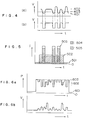
- Fig. 1 shows a time transition of a laser power P in a method of recording, reproducing and erasing information in accordance with the present invention.
- a recording track of an optical disk medium having a diameter of 130 mm and an In-Se recording film which enables rewriting of information by a phase change between a crystalline state and a near-amorphous state is rendered near-amorphous state in the record tracks, and an area between the record tracks is rendered crystalline state.
- the record track may also be rendered the crystalline state.
- the reflectivity of the crystalline state area is preferably substantially equal to a reflectivity of an erased area.
- the area between the record tracks is rendered completely crystalline state so that the area is prevented from gradually ununiformly crystallized by diffusion of heat to the area between the tracks when the information is rewritten resulting in mixture of pre-recorded information with a reproduced signal of new information (a kind of residual signal), or the increase of noise is prevented.
- the optical disk medium is rotated and a laser beam (continuous light) of a reproduce power level 101 is irradiated with a single light beam spot along the track to perform auto-focusing and tracking.
- the beam spot reaches a rewriting position (A)
- the power level is raised to a crystallization level (erase level) 102.
- the power level is pulsively raised to an amorphous power level (record level) 103. Then, the laser power is lowered to the crystallization level 102.
- the laser power is lowered to a level below the crystallization level (shown by a broken line between C and D) from the amorphous level and then the laser power is raised to the crystallization level. Thereafter, the recorded information is erased.
- an average laser power between C and D is preferably between 0 level and a power level immediately below the crystallization level 102, and more preferably between 1/4 and 3/4 of the crystallization power level.
- a carrier-to-noise (C/N) ratio measured at a band width of 30 KHz was approximately 50 dB.
- the same position was rewritten with a carrier of 0.9 MHz and a signal of 0.9 MHz was reproduced.
- a C/N ratio was again approximately 50 dB.
- the amorphous level (103) laser power was approximately 15 mW
- the crystallization level (102) laser power was approximately 7 mW
- the reproduce level (101) laser power was approximately 1 mW.
- the information may be recorded by returning the power level from the amorphizing level (103) to the crystallizing level (102), but when the cooling rate is lowered by the residual heat, the C/N ratio or S/N ratio of the reproduced signal may be degraded.
- a peak power shown by a broken line immediately after the laser power has been raised from the crystallization level 102 to the amorphous level 103 the amorphizing process of the recording film may be accelerated.
- the magnitude of the peak power may be higher than the amorphizing level 103 by upto a difference between the amorphizing level 103 and the crystallization level 102, and preferably between 1/4 to 3/4 of the level difference.
- the light beam spot is defocused in the erase mode. This is done by using a focusing lens having a color astigmatism to utilize the fact that the wavelength varies with a change of raser oscillation mode due to a change of laser power. If the beam spot is focused in the record mode, it is defocused when the laser power is at the erase level lower than the record level.
- Fig. 3 shows a construction of an optical record/reproduce/erase appratus used in the embodiment of the present invention.
- the optical system is essentially identical to an optical system for a commercially available write-once optical disk.
- Numeral 301 denotes an optical disk substrate
- numeral 302 denotes a recording film
- numeral 303 denotes a protective film
- numeral 304 denotes a focusing lens
- numeral 305 denotes a golvano-mirror
- numeral 306 denotes a quarter wavelength plate
- numeral 307 denotes a polarization prism
- numeral 308 denotes a prism
- numeral 309 denotes a coupling lens
- numeral 310 denotes a semiconductor laser
- numeral 311 denotes a filter
- numeral 312 denotes a convex lens
- numeral 313 denotes a half-mirror
- numeral 314 denotes a cylindrical
- the reflected light passes through the filter 311 during this mode before the reflected light is directed to an auto-focusing detector 316 and a tracking and signal reproducing detector 317 so that an incident light intensity is reduced.
- the output voltage of the detector may be attenuated during these modes.
- a comparator level 403 is set between a reproduced output voltage 401 of the amorphous area and a reproduced output voltage 402 of a least crystallized area to clip the waveform to produce a waveform shown in Fig. 4(b).
- the comparator level is set at an intermediate level of the voltage 401 and 402 or closer to the amorphous area output voltage, the detection is assured. If it is set closer to the crystallized area output voltage, the reproduced waveform is more exact to the original waveform.
- Either one of the crystallization state and amorphous state may be used for recorded state or erased state, respectively.
- the time at the amorphizing power level should be shorter than the time at the crystalizing power level.
- the recording pulse emission time is shorter and hence the amorphous state is preferably used for the recording.
- a current (hatched area 505) corresponding to a difference between the reproduce level and the crystallizing level of the rewriting area is superimposed to a laser drive pulse current (hatched area 504) of the commercial write-once optical disk apparatus to produce a current waveform shown by thick solid line. In this manner, a rewritable optical disk may be used.
- the top of the waveform is limited to prevent the amorphous level of the combined waveform from being too high.
- the information of the write-once optical disk can be recorded or reproduced by the rewritable optical disk apparatus.
- Fig. 2 shows a time transition of a laser power P in another method for recording, reproducing and erasing information.
- a record level 202 is lower than an erase level.
- the recording film, auto-focusing and tracking used in the present embodiment are identical to those of the Embodiment 1.
- the laser power is abruptly raised to the erase power level 203 and held at that level. During this period, the information is erased.
- the laser power is pulsively lowered to the record power level 202 to record information.
- the information may be recorded by only lowering the power to the record level 202 as described above, but if the laser power is lowered below the record level 202 as shown by a broken line between (b) and (c) at the beginning of lowering the power and then gradually raised to the record level 202, a time during which the recording area is at a recordable temperature is extended so that the recording is assured.
- the power level below the record level 202 is preferably just below the record level 202, and more preferably between 1/4 to 3/4 of the record level 202. Then, the laser power is raised to the erase level 203. As shown by a broken line between (c) and (d) in Fig.
- the power is raised above the erase level 203 and then lowered to the erase level 203 so that the erasing is assured.
- the average power between (c) and (d) may be the erase power level 203 plus a difference between the erase level 203 and the record level 202 and preferably 1/4 to 3/4 of such difference.
- the method for preventing the failure of erasing information is same as that of the Embodiment 1, and the information is recorded, reproduced and erased in the present embodiment by using the optical system of the Embodiment 1 shown in Fig. 1.
- Fig. 6a The change of the laser power P when multi-level recording is carried out in the present embodiment is shown in Fig. 6a and a reproduced voltage waveform V is shown in Fig. 6b.
- Numeral 601 denotes a reproduce level
- numeral 602 denotes a record level by crystallization
- numeral 603 denotes an erase level.
- the number of record states is three, but by increasing the number of levels, multi-level recording is attained, and by continuously changing the level, analog recording is attained. Since the change of power level and the change of reproduced voltage are normally not linearly related, at least one of the recording waveform and the reproduced waveform must be converted in order to attain a desired reproduced waveform.
- the present embodiment relates to a method effective to prevent reduction of a C/N ratio due to repetitive recording, reproducing and erasing of information.
- Fig. 7a shows a reproduced output waveform of pre-rewrite information
- Fig. 7b shows a time transistion of a laser power when recorded information is rewritten
- Fig. 7c shows a change of reflectivity of the recording film (change of reproduced output volage).
- the recording film may be either in the amorphous state or in the crystalline state.
- the laser power is raised from a low reproduce level 901 to a high amorphizing level 903 and held thereat. If information is present during this period, it is erased.
- the laser power is pulsively lowered to an intermediate crystallization level 902.
- the laser power is again raised to the high amorphous level 903 and the preexisting information is erased.
- information is recorded.
- the recording film is in the near-amorphous state
- the middle level laser power was irradiated
- the recording film is in the crystalline state.
- the power may be changed between the middle level and the high level. Either one of the crystalline state and the amorphous state may be selected as the record state or erase state, information "1" or "0", or high level or low level.
- the middle laser power level is preferably between 55% and 90% of the high level, and more preferably between 65% and 85%. If the middle level power is too high or too low, sufficient phase change is not attained during the irradiation.
- the S/N ratio was 3 dB lower than that in the more preferable range, and the S/N ratio was more than 6 dB lower in other range. This trend is essentially same for other recording film.
- a recording period When a recording period is short, complete crystallization may not be attained. If such record/erase process is repeated many times, the number of times of irradiation by the laser beam and the power level of the laser beam vary from place to place. As a result, the reflectivity may be non-uniform as shown in Fig. 7 depending on the degree of crystallization, type of crystal structure and degree of deformation. Thus, the C/N ratio may be lowered. The reflectivity may also vary during reading of information or when the recording film is placed in a high temperature atmosphere. Numeral 904 denotes a normal level of reflectivity.
- Such a change of reflectivity is monitored by a low level laser power during the rewrite mode, and if the reflectivity changes beyond a preset level 905, the information for that area is read and recorded at another area on the same disk, or written into another recording medium such as a memory IC. Then, a continuous light of a level to melt the recording film (amorphous level 903) as shown in Fig. 7d is irradiated to render the recording film completely amorphous. By such continuous light irradiation, the reflection level of the initial amorphous state is restored as shown in Fig. 7c. Then, the previously recorded information is overwritten.
- the information is not refuged to the other recording medium and the new information is recorded after the continuous light irradiation.
- the recorded information can be stably maintained for an extended time period. It is preferable to always monitor the reflectivity change.
- the above process may be automatically carried out at every predetermined number of times of rewriting, reading or reserving. Instead of continuous light irradiation at the amorphous power level, continuous light irradiation at the crystallization power level may be used.
- the change by the crystallization may appear not on the track but between tracks.
- the change is covered by the read light spot and a noise is detected.
- a target position of tracking may be intentionally shifted or a continuous light may be irradiated by another light beam to the area between tracks (which may be on the tracking groove or between grooves) to unify the change.
Landscapes
- Chemical & Material Sciences (AREA)
- Inorganic Chemistry (AREA)
- Physics & Mathematics (AREA)
- Engineering & Computer Science (AREA)
- Plasma & Fusion (AREA)
- Optical Recording Or Reproduction (AREA)
- Optical Record Carriers And Manufacture Thereof (AREA)
- Optical Head (AREA)
Claims (7)
- Verfahren zum erneuten Schreiben von Informationen auf ein Aufzeichnungsmedium, das bei Bestrahlung mit einem Energiestrahl eine Phasenänderung durchmacht, wobei die Strahlenergie zu Beginn der Ausbildung einer Aufzeichnungsmarke auf einen hohen Pegel (103) angehoben wird und am Ende der Ausbildung der Aufzeichnungsmarke einen mittleren Pegel (102) erreicht, wobei diese Schritte wiederholt werden, um eine Anzahl von Marken aufzuzeichnen,
dadurch gekennzeichnet, daß vor dem erneuten Schreiben ein niedriger Pegel (101) der Strahlenergie Verwendung findet, und daß die Strahlenergie zu Beginn des erneuten Schreibens der Aufzeichnungsmarke von diesem niedrigen Pegel (101) auf den mittleren Pegel (102) und dann auf den hohen Pegel (103) angehoben wird. - Verfahren nach Anspruch 1, wobei die Energie des Strahles am Ende der Ausbildung einer Aufzeichnungsmarke von dem hohen Pegel (103) auf einen Pegel erniedrigt wird, der niedriger ist als der mittlere Pegel, und dann auf den mittleren Pegel (102) zurückgekehrt wird.
- Verfahren nach Anspruch 1, wobei der mittlere oder der hohe Energiepegel das Aufzeichnungsmedium in einen relativ hoch kristallisierten Zustand versetzt.
- Verfahren nach Anspruch 3, wobei der andere Pegel, der nicht der mittlere oder der hohe Pegel ist, den Aufzeichnungsfilm in einen relativ gering kristallisierten Zustand versetzt.
- Verfahren nach Anspruch 1, wobei der hohe Pegel entsprechend dem Informationssignal dadurch variiert wird, daß einer Wellenform (505), die auf einem Pegel zwischen einem Pegel in einem Bereich vom Nullpegel bis zu einem Wiedergabepegel und einem anderen als diesem Pegel im wesentlichen konstant ist, eine Wellenform (504) überlagert wird, die zwischen einem Pegel in einem Bereich vom Nullpegel bis zu einem Wiedergabepegel und einem anderen als diesem Pegel variiert.
- Verfahren nach Anspruch 1, wobei, wenn der Energiepegel vom mittleren Pegel (102) zum hohen Pegel (103) angehoben wird, der Pegel über den hohen Pegel hinaus angehoben und dann auf den hohen Pegel erniedrigt wird.
- Verfahren nach Anspruch 1, wobei die Bestrahlungszeit des Energiestrahles am mittleren Pegel länger ist als die Bestrahlungszeit des Energiestrahles am hohen Pegel.
Applications Claiming Priority (7)
| Application Number | Priority Date | Filing Date | Title |
|---|---|---|---|
| JP61101130A JP2719130B2 (ja) | 1986-05-02 | 1986-05-02 | 情報の記録・再生および書き換え方法とその装置 |
| JP101130/86 | 1986-05-02 | ||
| JP61157822A JPS6313785A (ja) | 1986-07-07 | 1986-07-07 | 情報記録用薄膜 |
| JP157822/86 | 1986-07-07 | ||
| JP164826/86 | 1986-07-15 | ||
| JP16482686A JP2575119B2 (ja) | 1986-07-15 | 1986-07-15 | 情報の記録・再生方法 |
| EP87106312A EP0243976B1 (de) | 1986-05-02 | 1987-04-30 | Methode zur Aufzeichnung, Wiedergabe und zum Löschen von Informationen und Dünnfilm zur Aufzeichnung von Informationen |
Related Parent Applications (1)
| Application Number | Title | Priority Date | Filing Date |
|---|---|---|---|
| EP87106312.9 Division | 1987-04-30 |
Publications (3)
| Publication Number | Publication Date |
|---|---|
| EP0549562A2 EP0549562A2 (de) | 1993-06-30 |
| EP0549562A3 EP0549562A3 (en) | 1993-09-15 |
| EP0549562B1 true EP0549562B1 (de) | 1998-12-16 |
Family
ID=27309399
Family Applications (2)
| Application Number | Title | Priority Date | Filing Date |
|---|---|---|---|
| EP93100423A Expired - Lifetime EP0549562B1 (de) | 1986-05-02 | 1987-04-30 | Verfahren und Vorrichtung zur Aufzeichnung und Wiedergabe von Information |
| EP87106312A Expired - Lifetime EP0243976B1 (de) | 1986-05-02 | 1987-04-30 | Methode zur Aufzeichnung, Wiedergabe und zum Löschen von Informationen und Dünnfilm zur Aufzeichnung von Informationen |
Family Applications After (1)
| Application Number | Title | Priority Date | Filing Date |
|---|---|---|---|
| EP87106312A Expired - Lifetime EP0243976B1 (de) | 1986-05-02 | 1987-04-30 | Methode zur Aufzeichnung, Wiedergabe und zum Löschen von Informationen und Dünnfilm zur Aufzeichnung von Informationen |
Country Status (4)
| Country | Link |
|---|---|
| US (1) | US5123007A (de) |
| EP (2) | EP0549562B1 (de) |
| KR (1) | KR960002042B1 (de) |
| DE (2) | DE3752242T2 (de) |
Families Citing this family (28)
| Publication number | Priority date | Publication date | Assignee | Title |
|---|---|---|---|---|
| KR910003039B1 (ko) * | 1987-01-26 | 1991-05-17 | 가부시기가이샤 히다찌세이사꾸쇼 | 정보의 기록 재생 방법 |
| US5257256A (en) * | 1987-04-24 | 1993-10-26 | Hitachi, Ltd. | Recording waveform for mark-length modulation optical recording |
| US5291470A (en) * | 1988-03-28 | 1994-03-01 | Matsushita Electric Industrial Co., Ltd. | Optical information recording method |
| US4916688A (en) * | 1988-03-31 | 1990-04-10 | International Business Machines Corporation | Data storage method using state transformable materials |
| JPH01258243A (ja) * | 1988-04-08 | 1989-10-16 | Fujitsu Ltd | 互換型書き換え可能光ディスク |
| JP2512087B2 (ja) * | 1988-06-24 | 1996-07-03 | 株式会社日立製作所 | 光記録媒体および光記録方法 |
| US6052510A (en) * | 1988-09-19 | 2000-04-18 | Canon Kabushiki Kaisha | Apparatus for recording, reproduction or erasing |
| DE3906521A1 (de) * | 1989-03-02 | 1990-09-13 | Basf Ag | Verfahren zum auslesen von informationen, die in duennen polymerschichten gespeichert sind |
| JP2797733B2 (ja) * | 1990-03-14 | 1998-09-17 | 松下電器産業株式会社 | 光学情報記録部材の記録方法 |
| US5263015A (en) * | 1990-11-21 | 1993-11-16 | Hitachi, Ltd. | Magneto-optical recording media and overwrite recording method using the same |
| CN1083615A (zh) * | 1992-08-19 | 1994-03-09 | 菲利浦电子有限公司 | 信息存储系统 |
| JPH06162507A (ja) * | 1992-11-24 | 1994-06-10 | Toshiba Corp | 情報記録方法および情報記録装置 |
| US5548573A (en) * | 1993-11-04 | 1996-08-20 | Olympus Optical Co., Ltd. | Optical information reproducing apparatus provided with laser power control means for detecting reflected light from data region |
| DE19710115A1 (de) * | 1997-03-12 | 1998-09-17 | Henkel Kgaa | Schmelzklebstoff zur Verklebung von DVDs |
| JPH10289479A (ja) * | 1997-04-10 | 1998-10-27 | Tdk Corp | 光記録媒体 |
| KR19990065561A (ko) * | 1998-01-14 | 1999-08-05 | 구자홍 | 광 기록 방법 |
| JP4613356B2 (ja) * | 1998-03-03 | 2011-01-19 | 独立行政法人産業技術総合研究所 | 光記録媒体、光記録方法、光信号再生方法、光記録装置及び光信号再生装置 |
| US6477135B1 (en) * | 1998-03-26 | 2002-11-05 | Matsushita Electric Industrial Co., Ltd. | Optical information recording medium and method for recording and reproduction information thereon |
| DE19848146C2 (de) | 1998-10-20 | 2002-10-02 | Henkel Kgaa | Verwendung eines Schmelzklebstoffs zur Verklebung von DVDs und Verfahren zu deren Herstellung |
| KR100429843B1 (ko) * | 2001-09-22 | 2004-05-03 | 삼성전자주식회사 | 전자 방출 및 상변화물질을 이용한 고밀도정보기록/재생방법 및 이를 응용한 정보저장장치 및 이에사용되는 미디어 |
| EP1475784B1 (de) * | 2002-02-13 | 2014-12-24 | Mitsubishi Kagaku Media Co., Ltd. | Verfahren zur optischen aufzeichnung auf einem wiederbeschreibbaren optischen medium |
| JP3921393B2 (ja) * | 2002-02-14 | 2007-05-30 | Tdk株式会社 | 光記録媒体への情報記録方法、情報記録装置及び光記録媒体 |
| JP2004188422A (ja) * | 2002-12-06 | 2004-07-08 | Hamamatsu Photonics Kk | レーザ加工装置及びレーザ加工方法 |
| DE602004030576D1 (de) * | 2003-07-18 | 2011-01-27 | Mitsubishi Kagaku Media Co Ltd | Optisches aufzeichnungsverfahren |
| JP4102289B2 (ja) * | 2003-11-07 | 2008-06-18 | 株式会社日立製作所 | 情報記録方法、情報記録装置及び評価装置 |
| JP4458839B2 (ja) * | 2003-12-25 | 2010-04-28 | 株式会社ニデック | レーザ治療装置 |
| US7768729B2 (en) * | 2008-01-31 | 2010-08-03 | Hitachi Global Storage Technologies Netherlands B.V. | Method, system, and computer program product for estimating adjacent track erasure risk by determining erase band width growth rates |
| ES2628833T3 (es) * | 2011-08-01 | 2017-08-04 | Primetals Technologies Germany Gmbh | Método y aparato para una laminación continua |
Family Cites Families (41)
| Publication number | Priority date | Publication date | Assignee | Title |
|---|---|---|---|---|
| US3736046A (en) * | 1971-04-15 | 1973-05-29 | Honeywell Inc | Optical spot size changer |
| US3801966A (en) * | 1971-08-18 | 1974-04-02 | Hitachi Ltd | Optical memory device |
| JPS54103307A (en) * | 1978-01-31 | 1979-08-14 | Matsushita Electric Ind Co Ltd | Optical recorder-reproducer |
| JPS54143606A (en) * | 1978-04-28 | 1979-11-09 | Matsushita Electric Ind Co Ltd | Optical recorder-reproducer |
| US4285056A (en) * | 1979-10-17 | 1981-08-18 | Rca Corporation | Replicable optical recording medium |
| US4300227A (en) * | 1979-10-17 | 1981-11-10 | Rca Corporation | Replicable optical recording medium |
| FR2475270A1 (fr) * | 1980-02-01 | 1981-08-07 | Thomson Csf | Structure de memoire reversible, a inscription thermo-optique et lecture optique, et procede d'inscription et d'effacement de cette structure |
| US4383261A (en) * | 1980-08-21 | 1983-05-10 | The United States Of America As Represented By The Director Of The National Security Agency | Method for laser recording utilizing dynamic preheating |
| US4470053A (en) * | 1981-02-13 | 1984-09-04 | Minnesota Mining And Manufacturing Company | Protuberant optical recording medium |
| US4581717A (en) * | 1981-03-26 | 1986-04-08 | Sony Corporation | Thermomagnetic recording method |
| US4504938A (en) * | 1981-04-07 | 1985-03-12 | Victor Company Of Japan, Limited | Device for feedback controlling focus of an optical system in an information recording/reproducing apparatus |
| US4599718A (en) * | 1981-04-07 | 1986-07-08 | Tdk Electronics Co., Ltd. | Method for erasing a light recording medium |
| DE3275960D1 (en) * | 1982-01-06 | 1987-05-07 | Hitachi Ltd | Control circuit for controlling light source in optical disc device |
| JPS58137148A (ja) * | 1982-02-08 | 1983-08-15 | Sony Corp | 情報記録媒体 |
| US4488277A (en) * | 1982-02-10 | 1984-12-11 | North American Philips Corporation | Control system for an optical data recording apparatus |
| US4562567A (en) * | 1982-11-12 | 1985-12-31 | North American Philips Corporation | Apparatus for controlling the write beam in an optical data recording system |
| US4584259A (en) * | 1982-12-17 | 1986-04-22 | Burroughs Corporation | Coated media for optical recording with acrylic overcoat |
| DE3381422D1 (de) * | 1982-12-23 | 1990-05-10 | Sony Corp | Thermomagnetisches optisches aufzeichnungs-/wiedergabeverfahren. |
| US4586161A (en) * | 1983-05-11 | 1986-04-29 | General Electric Company | Permanent thermo-magnetic recording of binary digital information |
| US4665512A (en) * | 1983-09-29 | 1987-05-12 | Kabushiki Kaisha Toshiba | Optical head for erasing |
| DE3482347D1 (de) * | 1983-12-14 | 1990-06-28 | Hitachi Ltd | Geraet zum optischen aufzeichnen von informationen. |
| JPS60143438A (ja) * | 1983-12-30 | 1985-07-29 | Ricoh Co Ltd | 情報記録再生装置 |
| US4527173A (en) * | 1984-04-16 | 1985-07-02 | Eastman Kodak Company | Erasable, reusable optical recording element and method |
| JPS60231928A (ja) * | 1984-04-27 | 1985-11-18 | Matsushita Electric Ind Co Ltd | 光学情報記録消去方法 |
| US4716560A (en) * | 1984-05-22 | 1987-12-29 | Victor Company Of Japan, Ltd. | Recording disc and method for fabricating same |
| JPS60247827A (ja) * | 1984-05-24 | 1985-12-07 | Nec Corp | 光記憶書込回路 |
| US4679184A (en) * | 1984-06-08 | 1987-07-07 | Matsushita Electric Industrial Co., Ltd. | Optical recording and reproducing apparatus having erasing beam spot with asymmetrical intensity distribution |
| CA1245762A (en) * | 1984-06-15 | 1988-11-29 | Noboru Yamada | Reversible optical information recording medium |
| US4694447A (en) * | 1984-07-12 | 1987-09-15 | International Business Machines Corp. | Optical signal recorders employing two lasers and methods therefor |
| US4718053A (en) * | 1984-11-09 | 1988-01-05 | Hitachi, Ltd. | Optical information apparatus and method of recording and erasing information |
| JPS61126637A (ja) * | 1984-11-21 | 1986-06-14 | Olympus Optical Co Ltd | 光学的情報記録再生装置 |
| US4651172A (en) * | 1984-11-29 | 1987-03-17 | Hitachi, Ltd. | Information recording medium |
| JP2910767B2 (ja) * | 1984-11-30 | 1999-06-23 | 株式会社日立製作所 | 光ディスクおよび情報記録方法 |
| JPS61206937A (ja) * | 1985-03-08 | 1986-09-13 | Toshiba Corp | 光学的情報処理装置 |
| JPS61206951A (ja) * | 1985-03-11 | 1986-09-13 | Nippon Kogaku Kk <Nikon> | 同時消録型の光磁気記録兼再生装置のピツクアツプ |
| JPS61206952A (ja) * | 1985-03-11 | 1986-09-13 | Nippon Kogaku Kk <Nikon> | 同時消録型の光磁気記録及び再生兼用装置のピツクアツプ |
| US4695994A (en) * | 1985-04-05 | 1987-09-22 | Laser Magnetic Storage International Company | Method and apparatus for varying laser intensity level |
| JP2605015B2 (ja) * | 1985-06-26 | 1997-04-30 | インターナショナル・ビジネス・マシーンズ・コーポレーション | 熱誘導記録の情報担特信号レコーダ |
| US4737934A (en) * | 1985-10-18 | 1988-04-12 | Energy Conversion Devices, Inc. | Data storage device and system having an optically non transmissive chalcogenide layer |
| US4744055A (en) * | 1985-07-08 | 1988-05-10 | Energy Conversion Devices, Inc. | Erasure means and data storage system incorporating improved erasure means |
| US4815058A (en) * | 1985-10-21 | 1989-03-21 | Hitachi, Ltd. | Optical information processing apparatus |
-
1987
- 1987-04-30 DE DE3752242T patent/DE3752242T2/de not_active Expired - Lifetime
- 1987-04-30 EP EP93100423A patent/EP0549562B1/de not_active Expired - Lifetime
- 1987-04-30 DE DE3751891T patent/DE3751891T2/de not_active Expired - Lifetime
- 1987-04-30 EP EP87106312A patent/EP0243976B1/de not_active Expired - Lifetime
- 1987-05-01 KR KR1019870004266A patent/KR960002042B1/ko not_active IP Right Cessation
-
1990
- 1990-02-05 US US07/474,255 patent/US5123007A/en not_active Expired - Lifetime
Also Published As
| Publication number | Publication date |
|---|---|
| US5123007A (en) | 1992-06-16 |
| DE3752242D1 (de) | 1999-01-28 |
| DE3751891D1 (de) | 1996-10-10 |
| KR960002042B1 (ko) | 1996-02-09 |
| DE3751891T2 (de) | 1997-04-03 |
| EP0243976B1 (de) | 1996-09-04 |
| EP0243976A2 (de) | 1987-11-04 |
| EP0549562A3 (en) | 1993-09-15 |
| EP0243976A3 (en) | 1990-12-12 |
| DE3752242T2 (de) | 1999-08-19 |
| KR870011584A (ko) | 1987-12-24 |
| EP0549562A2 (de) | 1993-06-30 |
Similar Documents
| Publication | Publication Date | Title |
|---|---|---|
| EP0549562B1 (de) | Verfahren und Vorrichtung zur Aufzeichnung und Wiedergabe von Information | |
| US6205102B1 (en) | Method and device for recording an optical information carrier | |
| JP3259642B2 (ja) | 光ディスク記録方法 | |
| US5107482A (en) | Optical information recording method and apparatus and recording medium used therefor | |
| US6693864B2 (en) | Method and device for recording an information signal on an information layer of a recording medium | |
| JP3648914B2 (ja) | レーザ光のパワー制御方法及び光ディスク記録装置 | |
| JP2702923B2 (ja) | 情報の記録方法及び情報記録装置 | |
| US4980879A (en) | Optical information recording and erasing method using two laser beams on a phase change optical recording medium | |
| JP2719130B2 (ja) | 情報の記録・再生および書き換え方法とその装置 | |
| US5404348A (en) | Method for recording and reproducing information using at least two energy beams | |
| US6751513B1 (en) | Method and device for recording an optical information carrier | |
| US5084857A (en) | Information recording method using a modulated recording beam at high, intermediate and low power levels | |
| JP2728413B2 (ja) | 情報の記録・再生方法及び装置 | |
| US5673248A (en) | Phase change type optical recording apparatus and optical recording method using an overwrite system | |
| JP2575119B2 (ja) | 情報の記録・再生方法 | |
| JP2823152B2 (ja) | 情報の記録再生方法 | |
| JP2823154B2 (ja) | 情報の記録・再生および書き換え方法とその装置 | |
| JPH0227525A (ja) | 情報の記録・再生方法 | |
| JP2825013B2 (ja) | 情報の記録・再生および書き換え方法とその装置 | |
| JP3076083B2 (ja) | 光ディスク初期化方法及び光ディスク記録方法 | |
| JP2823153B2 (ja) | 情報の記録・再生および書き換え方法とその装置 | |
| JPH10112065A (ja) | 光学的情報記録媒体とその初期化方法および光学的情報装置 | |
| JPH09305971A (ja) | 情報記録方式及び情報記録再生装置 | |
| US7738335B2 (en) | Method and apparatus for recording information on an optical recording medium | |
| JP2833308B2 (ja) | 光ディスク記録装置 |
Legal Events
| Date | Code | Title | Description |
|---|---|---|---|
| PUAI | Public reference made under article 153(3) epc to a published international application that has entered the european phase |
Free format text: ORIGINAL CODE: 0009012 |
|
| 17P | Request for examination filed |
Effective date: 19930113 |
|
| AC | Divisional application: reference to earlier application |
Ref document number: 243976 Country of ref document: EP |
|
| AK | Designated contracting states |
Kind code of ref document: A2 Designated state(s): DE FR GB |
|
| PUAL | Search report despatched |
Free format text: ORIGINAL CODE: 0009013 |
|
| AK | Designated contracting states |
Kind code of ref document: A3 Designated state(s): DE FR GB |
|
| 17Q | First examination report despatched |
Effective date: 19960322 |
|
| GRAG | Despatch of communication of intention to grant |
Free format text: ORIGINAL CODE: EPIDOS AGRA |
|
| GRAG | Despatch of communication of intention to grant |
Free format text: ORIGINAL CODE: EPIDOS AGRA |
|
| GRAH | Despatch of communication of intention to grant a patent |
Free format text: ORIGINAL CODE: EPIDOS IGRA |
|
| GRAH | Despatch of communication of intention to grant a patent |
Free format text: ORIGINAL CODE: EPIDOS IGRA |
|
| GRAA | (expected) grant |
Free format text: ORIGINAL CODE: 0009210 |
|
| AC | Divisional application: reference to earlier application |
Ref document number: 243976 Country of ref document: EP |
|
| AK | Designated contracting states |
Kind code of ref document: B1 Designated state(s): DE FR GB |
|
| REF | Corresponds to: |
Ref document number: 3752242 Country of ref document: DE Date of ref document: 19990128 |
|
| ET | Fr: translation filed | ||
| PLBE | No opposition filed within time limit |
Free format text: ORIGINAL CODE: 0009261 |
|
| STAA | Information on the status of an ep patent application or granted ep patent |
Free format text: STATUS: NO OPPOSITION FILED WITHIN TIME LIMIT |
|
| 26N | No opposition filed | ||
| REG | Reference to a national code |
Ref country code: GB Ref legal event code: IF02 |
|
| PGFP | Annual fee paid to national office [announced via postgrant information from national office to epo] |
Ref country code: GB Payment date: 20060424 Year of fee payment: 20 Ref country code: FR Payment date: 20060424 Year of fee payment: 20 |
|
| PGFP | Annual fee paid to national office [announced via postgrant information from national office to epo] |
Ref country code: DE Payment date: 20060602 Year of fee payment: 20 |
|
| REG | Reference to a national code |
Ref country code: GB Ref legal event code: PE20 |
|
| PG25 | Lapsed in a contracting state [announced via postgrant information from national office to epo] |
Ref country code: GB Free format text: LAPSE BECAUSE OF EXPIRATION OF PROTECTION Effective date: 20070429 |