EP0543295A2 - Optischer Plattenspieler - Google Patents
Optischer Plattenspieler Download PDFInfo
- Publication number
- EP0543295A2 EP0543295A2 EP92119483A EP92119483A EP0543295A2 EP 0543295 A2 EP0543295 A2 EP 0543295A2 EP 92119483 A EP92119483 A EP 92119483A EP 92119483 A EP92119483 A EP 92119483A EP 0543295 A2 EP0543295 A2 EP 0543295A2
- Authority
- EP
- European Patent Office
- Prior art keywords
- tracking
- optical disk
- gain
- servo
- error signal
- Prior art date
- Legal status (The legal status is an assumption and is not a legal conclusion. Google has not performed a legal analysis and makes no representation as to the accuracy of the status listed.)
- Granted
Links
Images


Classifications
-
- G—PHYSICS
- G11—INFORMATION STORAGE
- G11B—INFORMATION STORAGE BASED ON RELATIVE MOVEMENT BETWEEN RECORD CARRIER AND TRANSDUCER
- G11B7/00—Recording or reproducing by optical means, e.g. recording using a thermal beam of optical radiation by modifying optical properties or the physical structure, reproducing using an optical beam at lower power by sensing optical properties; Record carriers therefor
- G11B7/08—Disposition or mounting of heads or light sources relatively to record carriers
- G11B7/09—Disposition or mounting of heads or light sources relatively to record carriers with provision for moving the light beam or focus plane for the purpose of maintaining alignment of the light beam relative to the record carrier during transducing operation, e.g. to compensate for surface irregularities of the latter or for track following
- G11B7/0945—Methods for initialising servos, start-up sequences
-
- G—PHYSICS
- G11—INFORMATION STORAGE
- G11B—INFORMATION STORAGE BASED ON RELATIVE MOVEMENT BETWEEN RECORD CARRIER AND TRANSDUCER
- G11B7/00—Recording or reproducing by optical means, e.g. recording using a thermal beam of optical radiation by modifying optical properties or the physical structure, reproducing using an optical beam at lower power by sensing optical properties; Record carriers therefor
- G11B7/08—Disposition or mounting of heads or light sources relatively to record carriers
- G11B7/085—Disposition or mounting of heads or light sources relatively to record carriers with provision for moving the light beam into, or out of, its operative position or across tracks, otherwise than during the transducing operation, e.g. for adjustment or preliminary positioning or track change or selection
- G11B7/08505—Methods for track change, selection or preliminary positioning by moving the head
- G11B7/08517—Methods for track change, selection or preliminary positioning by moving the head with tracking pull-in only
Definitions
- the present invention relates to an optical disk player and, more particularly, to an optical disk player which records and/or reproduces data on an optical disk.
- Optical disk players in which a laser beam is radiated onto an optical disk to write information on the disk or read information from it are widely used.
- Optical disks are effectively used as a medium to store voice and video signals and other forms of data, finding their applications in such apparatus as compact disk, television game, and video disk players.
- This track-following servo system has both a roughly operating actuator (thread mechanism) driven by a linear motor or other means to move an entire optical head in the radial direction of an optical disk and a biaxial mechanism to move the objective in the optical head in the tracking direction (parallel to the surface of the optical disk and across recording tracks) and focus direction (vertical to the surface of the optical disk and parallel to the optical axis of the objective).
- thread mechanism driven by a linear motor or other means to move an entire optical head in the radial direction of an optical disk
- a biaxial mechanism to move the objective in the optical head in the tracking direction (parallel to the surface of the optical disk and across recording tracks) and focus direction (vertical to the surface of the optical disk and parallel to the optical axis of the objective).
- a focus servo operation is activated to be closed and a rough spindle servo operation for a spindle motor to rotate the compact disk is performed, followed by a track positioning operation controlled by the biaxial mechanism to position the optical head to the specified recording track.
- the biaxial mechanism and the thread mechanism are controlled so that the laser beam correctly follow the recording track while, on the compact disk player, the rough spindle servo operation is activated to close the servo loop.
- optical disks on which data are recorded and/or reproduced by the optical disk player are slightly uneven from disk to disk in the reflectivity of the recording or reflective medium coated on disk or may have scratches on the recording medium.
- the tracking error signal is generated from the output of a detector which senses the laser beam reflected from the optical disk, an unstable tracking servo operation may result unless the status of the reflected beam is stable.
- the unstable tracking servo operation especially causes a lengthy tracking servo positioning operation.
- an optical disk player comprising: optical head means for recording and/or reproducing data by scanning a laser beam along tracks formed concentrically or spirally on the recording surface of optical disk; a tracking servo loop consisting of tracking error signal generating means and tracking driving means for operating the tracking mechanism of the optical head means based on a tracking error signal generated; and servo gain selecting means installed in the tracking servo loop for switching between a first gain suitable for a recording and/or reproducing operation and a second gain higher than the first; wherein a servo gain switch capable of selectively provide a first gain suitable for a recording/reproduction operation and a second gain higher than the first gain is provided inside a tracking servo loop consisting of a tracking error signal generator and a tracking driver for driving the tracking mechanism of the optical head based on a tracking error signal from the tracking error signal generator, wherein the second gain is kept selected by the servo gain selecting means only for the period until the completion of a tracking servo positioning
- Fig. 1 is a block diagram of an optical disk player as the preferred embodiment of the present invention.
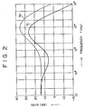
- Fig. 2 illustrates the tracking servo gain characteristics of the present invention.
- Fig. 3 is a flowchart depicting the operation of the controller for a tracking-in operation of the preferred embodiment of the present invention.
- a preferred embodiment of the present invention is described as follows. It should be noted that this embodiment will find its applications in apparatus including game playing apparatus which use an optical disk player and optical disks.
- Fig. 1 is a block diagram of the optical disk player, mainly showing its servo control system.
- Reference numeral 1 indicates an optical disk
- reference numeral 2 indicates a spindle motor for rotating the optical disk 1 at a constant linear velocity (CLV) for example
- reference numeral 3 indicates an optical head for radiating a laser beam onto the optical disk 1 and sensing the reflected beam from the optical disk 1 to obtain reproduced data.
- the optical head 3 has an optical system consisting of a semiconductor laser 3a, a polarized-beam splitter 3b, a quarter-wave plate 3c, an objective 3d, and a detector 3e.
- the optical head 3 also has a biaxial mechanism (fine actuator) 4 for driving the objective 3d serving as a laser output end in the direction of approaching or departing from the optical disk 1 and in its radial direction.
- the optical head 3 is driven in the radial direction of the optical disk 1 by a thread mechanism (rough actuator) 5.
- the optical head 3 contains, in the path of the laser beam emitted from the semiconductor laser 3a, a diffraction grating for separating the laser beam into three beams to obtain a tracking error signal. (Refer to US Patent No. 3876842, for example.)
- the optical head 3 also contains, between the polarized-beam splitter 3b and the detector 3e in the path of the reflected laser beam from the optical disk 1, an optical device such as a cylindrical lens for producing an astigmatism to obtain a focus error signal.
- an optical device such as a cylindrical lens for producing an astigmatism to obtain a focus error signal.
- For the generation of the focus error signal refer to U.S. Patent No. 4023033, for example.
- Reference numeral 6 indicates an RF amplifier for amplifying the reproduced RF signal coming from the optical head 3 and reference numeral 7 indicates a circuit for demodulating the reproduced RF signal to extract data.
- the demodulator/data extractor 7 provides the data reproduced from the optical disk 1 and the subcode data including time code and index information.
- Reference numeral 8 indicates a mechanical controller (hereinafter referred to simply as the controller) for controlling a recording and/or reproducing operation of the optical disk 1, based on control by a system controller, not shown.
- the controller 8 controls a laser beam on/off operation by the optical head 3, a spindle motor operation, and focus servo, spindle servo, and rough and fine tracking servo operations.
- Reference numeral 9 indicates an error signal generator for performing a specified operational processing on the reproduced RF signal from the optical head 3 to generate a tracking error signal Et and a focus error signal Ef.
- the generated tracking error signal Et is supplied through a servo gain amplifier section 10 and a phase compensator 11 to a thread driver 12 for driving the thread mechanism 5 and to a tracking driver 13 for driving the biaxial mechanism 4 in the direction parallel to the optical disk 1.
- the tracking driver 13 applies a tracking drive voltage to a biaxial mechanism 4 based on the tracking error signal Et to make the laser beam from the optical head 3 correctly follow tracks for a reproducing or recording operation.
- a thread driver 12 applies a drive voltage to the thread mechanism 5 to make it perform an access operation when recording/reproducing data or instructing a seek operation based on a control signal from the controller 8.
- the thread driver 24 also generates a drive signal based on the tracking error signal Et to feed the optical head 3 in the radial direction of the optical disk 1 at a recording/reproducing operation.
- the focus error signal Ef generated by the error signal generator 9 is supplied through a servo gain amplifier 14 and a phase compensator 15 to a focus driver 16 which drives the biaxial mechanism 4 in the direction vertical to the optical disk 1.
- the focus driver 16 applies a focus drive voltage to the biaxial mechanism 4 to perform focus control.
- Reference numeral 17 indicates a spindle servo system for controlling the rotational speed of a spindle motor 2.
- the spindle servo system 17 compares the clock component obtained by applying a reproduced RF signal to a PLL circuit in the demodulating/data extracting circuit 7 with the system clock from the controller 8 to generate a drive signal and supply it to the spindle motor 2 to provide a rotational driving operation at a constant linear velocity (CLV) for example.
- CLV constant linear velocity
- the gain-frequency characteristics of amplifiers G1 and G2 are shown in Fig. 2 in a solid line and a dashed line respectively.
- the focus servo system is first turned on to drive the biaxial mechanism 4 so that a laser beam is radiated onto the recording surface of the optical disk 1 at the focus position (F101).
- an actuating signal is applied to the spindle motor 2 to drive it (F102) and close the spindle servo system.
- the clock component obtained from the reproduced RF signal generated as a result of the above operation is compared with the system clock to perform a rough spindle control operation.
- the tracking servo system is turned on to drive the biaxial mechanism 4 and/or the thread mechanism 5 to perform a tracking servo positioning operation, in which a switching control signal is first applied to the servo gain amplifier 10 to make connection with a contact T2. That is, a tracking error signal Et provided with a servo gain given by the amplifier G2 having the characteristic represented in the dashed line in Fig. 2 is applied to the tracking driver 13 and the thread driver 12 (F104). The tracking servo system is then turned on to perform a tracking servo positioning operation (F105).
- the completion of the tracking servo positioning operation is confirmed when the subcode has been read from the reproduced RF signal from the optical disk 1 upon completion of a spindle servo latching operation at the time a match has been found between the phase of the clock component obtained from the reproduced RF signal and the phase of the reference clock.
- a switching control signal is applied again to the servo gain amplifier section 10 to switch the selector S to a contact T1. That is, the tracking error signal with a servo gain given by the amplifier G1 having the characteristic represented in the solid line in Fig. 2 is applied to the tracking driver 13 and the thread driver 12 (F107), thereafter controlling the track-following operation by the biaxial mechanism 4 based on this tracking error signal Et and the track-following operation and seek operation (track long jump operation) by the thread mechanism 5 as usual.
- raising a tracking servo gain only during a tracking servo positioning operation stabilizes the tracking servo positioning operation, thereby shortening the tracking servo positioning time and preventing servo noises from generating at turning on the tracking servo system.
- an optical disk player which increases a tracking servo gain only during a tracking servo positioning operation to stabilize the operation, thereby shortening the tracking servo positioning time and preventing servo noises from being generated.
Landscapes
- Optical Recording Or Reproduction (AREA)
- Moving Of The Head To Find And Align With The Track (AREA)
- Moving Of The Head For Recording And Reproducing By Optical Means (AREA)
Applications Claiming Priority (2)
| Application Number | Priority Date | Filing Date | Title |
|---|---|---|---|
| JP03332857A JP3074877B2 (ja) | 1991-11-22 | 1991-11-22 | 光ディスクプレーヤ |
| JP332857/91 | 1991-11-22 |
Publications (3)
| Publication Number | Publication Date |
|---|---|
| EP0543295A2 true EP0543295A2 (de) | 1993-05-26 |
| EP0543295A3 EP0543295A3 (de) | 1994-01-12 |
| EP0543295B1 EP0543295B1 (de) | 1997-03-05 |
Family
ID=18259583
Family Applications (1)
| Application Number | Title | Priority Date | Filing Date |
|---|---|---|---|
| EP92119483A Expired - Lifetime EP0543295B1 (de) | 1991-11-22 | 1992-11-13 | Optischer Plattenspieler |
Country Status (4)
| Country | Link |
|---|---|
| US (1) | US5436877A (de) |
| EP (1) | EP0543295B1 (de) |
| JP (1) | JP3074877B2 (de) |
| DE (1) | DE69217836T2 (de) |
Cited By (4)
| Publication number | Priority date | Publication date | Assignee | Title |
|---|---|---|---|---|
| EP1091351A1 (de) * | 1998-05-27 | 2001-04-11 | Matsushita Electronics Corporation | Optische plattenvorrichtung |
| CN1071916C (zh) * | 1994-06-02 | 2001-09-26 | 索尼公司 | 一次写入的光盘记录装置 |
| US7839732B2 (en) | 2007-04-14 | 2010-11-23 | Mediatek Inc. | System and method for calibrating recording track offset of optical storage device |
| CN101286326B (zh) * | 2007-04-14 | 2011-08-17 | 联发科技股份有限公司 | 用来校正光学储存装置的记录轨道偏移的方法与系统 |
Families Citing this family (12)
| Publication number | Priority date | Publication date | Assignee | Title |
|---|---|---|---|---|
| US5677899A (en) | 1991-02-15 | 1997-10-14 | Discovision Associates | Method for moving carriage assembly from initial position to target position relative to storage medium |
| US5729511A (en) | 1991-02-15 | 1998-03-17 | Discovision Associates | Optical disc system having servo motor and servo error detection assembly operated relative to monitored quad sum signal |
| US6236625B1 (en) | 1991-02-15 | 2001-05-22 | Discovision Associates | Optical disc system having current monitoring circuit with controller for laser driver and method for operating same |
| US5825729A (en) * | 1993-12-15 | 1998-10-20 | Canon Kabushiki Kaisha | Information recording and/or reproducing method and apparatus in which a servo process of a light beam is interrupted between input/output control of data at predetermined periods |
| JP3336778B2 (ja) * | 1994-11-25 | 2002-10-21 | 松下電器産業株式会社 | トラッキング誤差検出装置 |
| US6434087B1 (en) | 1995-01-25 | 2002-08-13 | Discovision Associates | Optical disc system and method for controlling bias coil and light source to process information on a storage medium |
| KR0156861B1 (ko) * | 1995-11-27 | 1998-12-15 | 김광호 | 하드디스크 드라이브에 있어서 서보제어 이득 자동 보상방법 |
| US5982721A (en) * | 1996-03-29 | 1999-11-09 | Cirrus Logic, Inc. | Optical disc drive comprising switching gains for forcing phase states to follow a sliding line trajectory in a servo system |
| JP2002150576A (ja) * | 2000-11-14 | 2002-05-24 | Sony Corp | 再生装置および方法、並びに記録媒体 |
| TWI253636B (en) * | 2003-11-19 | 2006-04-21 | Mediatek Inc | Apparatus with switching servo gain and offset for optical disk device and method thereof |
| JPWO2009001499A1 (ja) * | 2007-06-28 | 2010-08-26 | パナソニック株式会社 | 光ディスク用信号処理装置、光ディスク再生記録装置、および光ディスク用信号処理方法 |
| US20090196133A1 (en) * | 2008-02-04 | 2009-08-06 | Chia-Wei Liang | Signal processing apparatus for optical disc and method thereof |
Citations (4)
| Publication number | Priority date | Publication date | Assignee | Title |
|---|---|---|---|---|
| JPS5938973A (ja) * | 1982-08-28 | 1984-03-03 | Sony Corp | デイスク再生装置 |
| JPS60258775A (ja) * | 1984-06-06 | 1985-12-20 | Toshiba Corp | デイスク再生装置のトラツキング制御回路 |
| EP0265287A2 (de) * | 1986-10-24 | 1988-04-27 | Pioneer Electronic Corporation | Servovorrichtung für einen Schlitten |
| EP0305191A2 (de) * | 1987-08-28 | 1989-03-01 | Fujitsu Limited | Spurservoregelungssystem für optisches Plattengerät |
Family Cites Families (9)
| Publication number | Priority date | Publication date | Assignee | Title |
|---|---|---|---|---|
| JPS58189842A (ja) * | 1982-04-30 | 1983-11-05 | Toshiba Corp | 光学式デジタルデイスクプレ−ヤ装置 |
| JPS61977A (ja) * | 1984-06-13 | 1986-01-06 | Pioneer Electronic Corp | トラツキングサ−ボ装置 |
| JPS61177642A (ja) * | 1985-01-31 | 1986-08-09 | Olympus Optical Co Ltd | 光学的情報記録再生装置 |
| JPS61233435A (ja) * | 1985-04-09 | 1986-10-17 | Matsushita Electric Ind Co Ltd | サ−ボゲイン制御装置 |
| US4761692A (en) * | 1986-04-15 | 1988-08-02 | Pioneer Electronic Corporation | Method and apparatus for data recording disc playback |
| JPH02103790A (ja) * | 1988-10-11 | 1990-04-16 | Pioneer Electron Corp | トラッキングサーボ装置 |
| JPH02113437A (ja) * | 1988-10-21 | 1990-04-25 | Fujitsu Ltd | 光ディスク装置のサーボagc回路 |
| JPH02247831A (ja) * | 1989-03-20 | 1990-10-03 | Pioneer Electron Corp | トラッキングサーボループのループゲイン設定方法 |
| US5210732A (en) * | 1990-11-27 | 1993-05-11 | Matsushita Electric Industrial Co., Ltd. | Optical disk apparatus |
-
1991
- 1991-11-22 JP JP03332857A patent/JP3074877B2/ja not_active Expired - Lifetime
-
1992
- 1992-11-13 EP EP92119483A patent/EP0543295B1/de not_active Expired - Lifetime
- 1992-11-13 DE DE69217836T patent/DE69217836T2/de not_active Expired - Lifetime
-
1994
- 1994-09-06 US US08/301,134 patent/US5436877A/en not_active Expired - Lifetime
Patent Citations (4)
| Publication number | Priority date | Publication date | Assignee | Title |
|---|---|---|---|---|
| JPS5938973A (ja) * | 1982-08-28 | 1984-03-03 | Sony Corp | デイスク再生装置 |
| JPS60258775A (ja) * | 1984-06-06 | 1985-12-20 | Toshiba Corp | デイスク再生装置のトラツキング制御回路 |
| EP0265287A2 (de) * | 1986-10-24 | 1988-04-27 | Pioneer Electronic Corporation | Servovorrichtung für einen Schlitten |
| EP0305191A2 (de) * | 1987-08-28 | 1989-03-01 | Fujitsu Limited | Spurservoregelungssystem für optisches Plattengerät |
Non-Patent Citations (2)
| Title |
|---|
| PATENT ABSTRACTS OF JAPAN vol. 10, no. 140 (P-458)(2197) 23 May 1986 & JP-A-60 258 775 (TOSHIBA) 20 December 1985 * |
| PATENT ABSTRACTS OF JAPAN vol. 8, no. 141 (P-283)30 June 1984 & JP-A-59 038 973 (SONY) 3 March 1984 * |
Cited By (5)
| Publication number | Priority date | Publication date | Assignee | Title |
|---|---|---|---|---|
| CN1071916C (zh) * | 1994-06-02 | 2001-09-26 | 索尼公司 | 一次写入的光盘记录装置 |
| EP1091351A1 (de) * | 1998-05-27 | 2001-04-11 | Matsushita Electronics Corporation | Optische plattenvorrichtung |
| EP1091351A4 (de) * | 1998-05-27 | 2005-01-05 | Matsushita Electronics Corp | Optische plattenvorrichtung |
| US7839732B2 (en) | 2007-04-14 | 2010-11-23 | Mediatek Inc. | System and method for calibrating recording track offset of optical storage device |
| CN101286326B (zh) * | 2007-04-14 | 2011-08-17 | 联发科技股份有限公司 | 用来校正光学储存装置的记录轨道偏移的方法与系统 |
Also Published As
| Publication number | Publication date |
|---|---|
| EP0543295B1 (de) | 1997-03-05 |
| JP3074877B2 (ja) | 2000-08-07 |
| DE69217836D1 (de) | 1997-04-10 |
| DE69217836T2 (de) | 1997-06-12 |
| EP0543295A3 (de) | 1994-01-12 |
| US5436877A (en) | 1995-07-25 |
| JPH05144020A (ja) | 1993-06-11 |
Similar Documents
| Publication | Publication Date | Title |
|---|---|---|
| EP0294490B1 (de) | Eine optische platte diskriminierendes gerät | |
| US6445649B1 (en) | Apparatus and method for controlling movement of an optical head | |
| EP0543295B1 (de) | Optischer Plattenspieler | |
| US5715232A (en) | Recording and reproduction of items of information using ROM-RAM storage media | |
| JPH04364229A (ja) | 光方式記録再生方法および記録媒体、光方式記録再生装置 | |
| US5914921A (en) | Disk drive apparatus initializing optical head during acceleration of disk, detecting control information and adjusting light emission prior to disk reaching a constant speed of rotation | |
| JPH10112043A (ja) | 再生装置 | |
| US4918680A (en) | Focus-servo correction utilizing storage of detected focus errors | |
| US5835466A (en) | Optical system for optical disc having first and second information | |
| EP0811972B1 (de) | Aufzeichnungsgerät einer magneto-optischen Platte | |
| US4942567A (en) | Disk reproducing method | |
| JP2000222744A (ja) | 光ディスク装置およびフォーカスサーボ制御装置 | |
| KR20010059876A (ko) | 광 기록재생기의 제어 방법 | |
| US5872753A (en) | Optical disk driving apparatus with tracking control | |
| JP2925490B2 (ja) | 情報記録再生装置 | |
| JPH09219056A (ja) | ディスク再生方法およびその装置 | |
| JP2003263752A (ja) | 光ディスク記録再生装置 | |
| KR100272377B1 (ko) | 기록형 디스크의 데이터 재생방법 | |
| US20030063537A1 (en) | Disk reproducer | |
| JPH0927131A (ja) | 光ディスク装置 | |
| JPH09161284A (ja) | フォーカス引き込み方法および光ディスクドライブ装置 | |
| JPH033119A (ja) | 光ディスク装置 | |
| JPH04141829A (ja) | 光ディスク駆動装置 | |
| JPH06251384A (ja) | Cdプレーヤアクセス方法 | |
| JPH10241265A (ja) | ディスク装置の再生位置検出方法およびシーク動作制御方法 |
Legal Events
| Date | Code | Title | Description |
|---|---|---|---|
| PUAI | Public reference made under article 153(3) epc to a published international application that has entered the european phase |
Free format text: ORIGINAL CODE: 0009012 |
|
| AK | Designated contracting states |
Kind code of ref document: A2 Designated state(s): DE FR GB |
|
| PUAL | Search report despatched |
Free format text: ORIGINAL CODE: 0009013 |
|
| AK | Designated contracting states |
Kind code of ref document: A3 Designated state(s): DE FR GB |
|
| 17P | Request for examination filed |
Effective date: 19940610 |
|
| 17Q | First examination report despatched |
Effective date: 19951201 |
|
| GRAG | Despatch of communication of intention to grant |
Free format text: ORIGINAL CODE: EPIDOS AGRA |
|
| GRAH | Despatch of communication of intention to grant a patent |
Free format text: ORIGINAL CODE: EPIDOS IGRA |
|
| GRAH | Despatch of communication of intention to grant a patent |
Free format text: ORIGINAL CODE: EPIDOS IGRA |
|
| GRAA | (expected) grant |
Free format text: ORIGINAL CODE: 0009210 |
|
| AK | Designated contracting states |
Kind code of ref document: B1 Designated state(s): DE FR GB |
|
| REF | Corresponds to: |
Ref document number: 69217836 Country of ref document: DE Date of ref document: 19970410 |
|
| ET | Fr: translation filed | ||
| PLBE | No opposition filed within time limit |
Free format text: ORIGINAL CODE: 0009261 |
|
| STAA | Information on the status of an ep patent application or granted ep patent |
Free format text: STATUS: NO OPPOSITION FILED WITHIN TIME LIMIT |
|
| 26N | No opposition filed | ||
| REG | Reference to a national code |
Ref country code: GB Ref legal event code: IF02 |
|
| PGFP | Annual fee paid to national office [announced via postgrant information from national office to epo] |
Ref country code: DE Payment date: 20101119 Year of fee payment: 19 |
|
| PGFP | Annual fee paid to national office [announced via postgrant information from national office to epo] |
Ref country code: GB Payment date: 20101118 Year of fee payment: 19 |
|
| PGFP | Annual fee paid to national office [announced via postgrant information from national office to epo] |
Ref country code: FR Payment date: 20111130 Year of fee payment: 20 |
|
| REG | Reference to a national code |
Ref country code: DE Ref legal event code: R071 Ref document number: 69217836 Country of ref document: DE |
|
| REG | Reference to a national code |
Ref country code: DE Ref legal event code: R071 Ref document number: 69217836 Country of ref document: DE |
|
| REG | Reference to a national code |
Ref country code: GB Ref legal event code: PE20 Expiry date: 20121112 |
|
| PG25 | Lapsed in a contracting state [announced via postgrant information from national office to epo] |
Ref country code: GB Free format text: LAPSE BECAUSE OF EXPIRATION OF PROTECTION Effective date: 20121112 |