EP0540848B1 - Affût à bague rotatif pour arme légère sur un véhicule blindé de combat, en particulier sur la trappe d'un char - Google Patents
Affût à bague rotatif pour arme légère sur un véhicule blindé de combat, en particulier sur la trappe d'un char Download PDFInfo
- Publication number
- EP0540848B1 EP0540848B1 EP92115029A EP92115029A EP0540848B1 EP 0540848 B1 EP0540848 B1 EP 0540848B1 EP 92115029 A EP92115029 A EP 92115029A EP 92115029 A EP92115029 A EP 92115029A EP 0540848 B1 EP0540848 B1 EP 0540848B1
- Authority
- EP
- European Patent Office
- Prior art keywords
- hatch
- rotating ring
- carriage
- arc length
- running rails
- Prior art date
- Legal status (The legal status is an assumption and is not a legal conclusion. Google has not performed a legal analysis and makes no representation as to the accuracy of the status listed.)
- Expired - Lifetime
Links
Images

Classifications
-
- F—MECHANICAL ENGINEERING; LIGHTING; HEATING; WEAPONS; BLASTING
- F16—ENGINEERING ELEMENTS AND UNITS; GENERAL MEASURES FOR PRODUCING AND MAINTAINING EFFECTIVE FUNCTIONING OF MACHINES OR INSTALLATIONS; THERMAL INSULATION IN GENERAL
- F16C—SHAFTS; FLEXIBLE SHAFTS; ELEMENTS OR CRANKSHAFT MECHANISMS; ROTARY BODIES OTHER THAN GEARING ELEMENTS; BEARINGS
- F16C19/00—Bearings with rolling contact, for exclusively rotary movement
- F16C19/50—Other types of ball or roller bearings
-
- F—MECHANICAL ENGINEERING; LIGHTING; HEATING; WEAPONS; BLASTING
- F41—WEAPONS
- F41A—FUNCTIONAL FEATURES OR DETAILS COMMON TO BOTH SMALLARMS AND ORDNANCE, e.g. CANNONS; MOUNTINGS FOR SMALLARMS OR ORDNANCE
- F41A27/00—Gun mountings permitting traversing or elevating movement, e.g. gun carriages
- F41A27/06—Mechanical systems
- F41A27/08—Bearings, e.g. trunnions; Brakes or blocking arrangements
- F41A27/16—Bearings, e.g. trunnions; Brakes or blocking arrangements using raceway bearings, e.g. for supporting the turret
-
- F—MECHANICAL ENGINEERING; LIGHTING; HEATING; WEAPONS; BLASTING
- F41—WEAPONS
- F41H—ARMOUR; ARMOURED TURRETS; ARMOURED OR ARMED VEHICLES; MEANS OF ATTACK OR DEFENCE, e.g. CAMOUFLAGE, IN GENERAL
- F41H5/00—Armour; Armour plates
- F41H5/22—Manhole covers, e.g. on tanks; Doors on armoured vehicles or structures
- F41H5/223—Manhole covers specially adapted for armoured or fighting vehicles
Definitions
- the invention relates to a rotating ring mount for a light weapon on a combat vehicle, in particular on a hatch of a main battle tank, with a carriage carrying the weapon, which is guided on guide rails on curved tracks.
- Such rotating ring guns are known per se.
- the known rotating ring guns have running rails which have the shape of a closed circular ring, so that the carriage carrying the weapon can be moved freely around 360 ° and more and thus covers the full azimuth range. If the rotating ring mount is arranged on a conventional hatch that can be closed with a hinged lid, missing pieces become the running rails are generally supplemented by insertable segments, which are attached, for example, to the hatch cover, so that again running rails are available in the form of a full circular arc.
- Main battle tanks are known (see DE-OS 33 05 882) with a hatch arranged on the top of the vehicle trough or the tower and closable with a cover, in which the hatch cover is constructed from two cover parts of different masses which are arranged one above the other in the closed position, the upper, heavier cover part being arranged above the upper edge of the hatch opening and being displaceable parallel to the closing plane of the hatch, while the lower, lighter cover part can be arranged on the underside of the upper cover part and being movable perpendicular to the closing plane of the hatch.
- the sealing of the hatch opening is achieved by the interaction of the two cover parts.
- the invention has for its object to provide a rotating ring mount of the type specified in the preamble of claim 1 in such a way that safe guidance of the carriage carrying the weapon is achieved without any additional segments having to be inserted into the running tracks in order to have the shape of a closed one Achieve circular arc.
- the basic idea of the invention is to design the running tracks only in the form of partial arcs with a more or less large gap in the circumferential direction and instead to design the carriage in the form of a partial circular ring which extends over such an arc length that it not only the gap in the Partial arcs of the rails bridged, but that when crossing these gaps even if its one end is above the gap and is therefore not supported, it is securely supported and guided at the other end.
- the design of the rotating ring mount according to the invention is particularly advantageous, in particular in battle tanks with sliding hatches.
- the arrangement in this case is such that the trajectory of the sliding hatch runs exactly through the gap in the partial arcs of the running rails.
- the hatch between the open ends of the carriage is then easily possible in the rest position of the carriage, in which the carriage and rails cover exactly the same arc section and to move the rails in the opening direction.
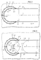
- Fig. 1 shows a battle tank tower KPT with an exit hatch 1, which can be closed by means of a hatch cover 2 which can be moved in the longitudinal direction of the tower.
- a rotating ring mount 4, which carries a light weapon 5, is arranged on the hatch.
- FIGS. 2 to 6 The more precise arrangement and design of the rotating ring mount and its position in relation to the hatch cover can be seen in FIGS. 2 to 6.
- FIG. 2 shows the hatch in the closed state, the hatch cover being locked in the closed position by a first locking device 7.1.
- the hatch cover 2 is guided over guide rollers, not shown, in guide rails 3.1 and 3.2.
- Around a part of the circumference of the hatch 1 extend rails 4.1, 4.2, on which a carriage 4.3 is guided over guide rollers 6, which carries the weapon 5, which is only indicated by its fastening device 5.1.
- the tracks 4.1 and 4.2 each have the shape of a partial arc, whereby in the illustrated embodiment the outer track 4.1 extends over an arc length of 1.44 ⁇ at an angle of 260 ° and the inner track 4.2 extends over an arc length of 1.26 ⁇ at an angle of 227 ° ( see Fig. 3).
- the carriage 4.3 has the shape of a partial circular ring with an arc length which corresponds approximately to the arc length of the outer track 4.1 on the outer edge and approximately the arc length of the inner track 4.2 at the inner edge. As can be seen from FIGS. 2 and 3, are in the rest position of the carriage 4.3 with the weapon facing forward in the direction of arrow L 5 carriages 4.3 and rails 4.1 and 4.2, one on top of the other.
- the locking 7.1 of the hatch cover 2 is released. Then the hatch cover is moved in the arrow direction A into the open position and finally locked in the open position by the second locking device 7.2. Now the open area between the ends of the rails 4.1 and 4.2 is free, so that a rotation of the carriage 4.3 is possible.
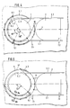
- 4 shows a first rotation from the rest position by an angle of approximately 65 ° azimuth. In this position, the carriage 4.3 is still supported on the running rails for approximately three-quarters of its arc length. The remaining quarter protrudes into the open part between the ends of the rails 4.1 and 4.2.
- the support length remains, which in the worst case still corresponds to more than half the total length of the carriage.
- an additional guide 10 is arranged, which supports the lateral guidance of the ends of the carriage when the hatch cover is open when the carriage 4.3 is rotated.
- Fig. 6 the guidance of the carriage on the rails is shown in more detail.
- the rails 4.2 and 4.1 are arranged at the ends of a step ring 4.4 and are therefore at different heights.
- the step ring 4.4 is supported by a connecting ring 8.1 on a bearing ring 8, which is arranged on the roof plate of the main battle turret.
- guide rollers 6.1 are arranged, the axes of rotation of which are perpendicular to the plane of the rotating ring, while on the inside of the carriage 4.3, guide rollers 6.2 are arranged, the axes of rotation of which are also perpendicular to the rotating ring level.
- the guide rollers 6.1 and 6.2 have conical grooves or guide grooves on their running surfaces, in which the correspondingly configured ends of the running rails 4.1 and 4.2 engage. In this way it is achieved that vertical loads are well absorbed and at the same time a harmonious circular movement is achieved.
- the guide rollers are on the carriage.
- the guide rollers are arranged on the running rails and there are counter rails on the carriage which engage in the guide rollers.
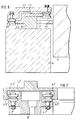
- FIG. 7 This variant of the exemplary embodiment is shown in FIG. 7.
- the rails 4.1 'and 4.2' are arranged on a connecting ring 8 ', which is arranged in a manner not shown on the roof plate of the battle tank tower.
- the guide rollers 6.1 'and 6.2' are arranged on the running rails 4.1 'and 4.2', while on the carriage 4.3 'opposing rails 4.5' and 4.6 'are arranged which engage in the guide rollers 6.1' and 6.2 '.
- the design and mode of operation of the exemplary embodiment correspond to the exemplary embodiment illustrated with reference to FIGS. 2 to 6.
Landscapes
- Engineering & Computer Science (AREA)
- General Engineering & Computer Science (AREA)
- Mechanical Engineering (AREA)
- Toys (AREA)
- Aiming, Guidance, Guns With A Light Source, Armor, Camouflage, And Targets (AREA)
- Fittings On The Vehicle Exterior For Carrying Loads, And Devices For Holding Or Mounting Articles (AREA)
Claims (5)
- Affût à bague rotative pour une arme légère montée sur un véhicule de combat, en particulier sur une écoutille d'un char blindé, comportant un chariot supportant l'arme, lequel est guidé par des rouleaux de guidage se déplaçant sur des rails recourbés en forme de cercle, caractérisé en ce que les rails (4.1, 4.2) présentent la forme d'un arc de cercle gradué à radian prédéterminé supérieur à π et inférieur à 2 π, et en ce que le chariot (4.3) présente la forme d'un cercle gradué dont le radian est supérieur à la différence entre le radian 2 π du cercle complet et le radian des rails.
- Affût à bague rotative selon la revendication 1, caractérisé en ce que le radian du cercle gradué du chariot (4.3) correspont sensiblement à celui des longueurs du cercle gradué des rails (4.1, 4.2).
- Affût à bague rotative selon la revendication 2, caractérisé en ce que le radian du cercle du chariot (4.3) est gradué et les radians des arcs de cercle des rails (4.1, 4.2) sont compris sensiblement entre 5/4 π et 3/2 π.
- Affût à bague rotative selon l'une des revendications 1 à 3, caractérisé en ce que le chariot (4.3) présente sur son côté intérieur et son côté extérieur des rouleaux de guidage (6.1, 6.2) placés sur le pourtour, dont les axes de rotation sont perpendiculaires au plan de la bague rotative, chaque rouleau de guidage (6.1, 6.2) présentant, sur sa surface de roulement, une rainure conique de guidage dans laquelle pénètrent les rails correspondants dans une direction parallèle au plan de la bague rotative.
- Affût à bague rotative selon l'une des revendications 1 à 4, caractérisé en ce qu'il est disposé sur une écoutille d'entrée et de sortie (1) d'un char blindé, laquelle est obturable par un panneau (2) qui présente une partie de panneau disposée au-dessus du bord supérieur de l'ouverture de l'écoutille, cette partie pouvant coulisser parallèlement au plan de fermeture de l'écoutille, les rails (4.1, 4.2) de l'affût étant disposés symétriquement par rapport à la direction de déplacement (A) de la partie (2) du panneau et le trajet de déplacement de cette partie (2) du panneau passant à travers la partie ouverte des arcs de cercle gradués.
Applications Claiming Priority (2)
| Application Number | Priority Date | Filing Date | Title |
|---|---|---|---|
| DE4136602A DE4136602A1 (de) | 1991-11-07 | 1991-11-07 | Drehringlafette fuer eine leichte waffe an einem kampffahrzeug, insbesondere an einer luke eines kampfpanzers |
| DE4136602 | 1991-11-07 |
Publications (2)
| Publication Number | Publication Date |
|---|---|
| EP0540848A1 EP0540848A1 (fr) | 1993-05-12 |
| EP0540848B1 true EP0540848B1 (fr) | 1995-04-26 |
Family
ID=6444244
Family Applications (1)
| Application Number | Title | Priority Date | Filing Date |
|---|---|---|---|
| EP92115029A Expired - Lifetime EP0540848B1 (fr) | 1991-11-07 | 1992-09-03 | Affût à bague rotatif pour arme légère sur un véhicule blindé de combat, en particulier sur la trappe d'un char |
Country Status (3)
| Country | Link |
|---|---|
| US (1) | US5285714A (fr) |
| EP (1) | EP0540848B1 (fr) |
| DE (2) | DE4136602A1 (fr) |
Cited By (1)
| Publication number | Priority date | Publication date | Assignee | Title |
|---|---|---|---|---|
| WO2011000727A1 (fr) | 2009-07-03 | 2011-01-06 | Aktiebolaget Skf | Ensemble palier |
Families Citing this family (8)
| Publication number | Priority date | Publication date | Assignee | Title |
|---|---|---|---|---|
| US20070251375A1 (en) * | 2006-04-28 | 2007-11-01 | Lockheed Martin Corporation | Segmented gun turret for quick assembly |
| US8342073B2 (en) * | 2009-07-27 | 2013-01-01 | Battelle Energy Alliance, Llc | Composite armor, armor system and vehicle including armor system |
| DE102011008698A1 (de) | 2011-01-15 | 2012-07-19 | Rheinmetall Landsysteme Gmbh | Lafette |
| DE102011008699B4 (de) | 2011-01-15 | 2016-12-08 | Rheinmetall Landsysteme Gmbh | Schutzvorrichtung für insbesondere eine Luke |
| FR3002030B1 (fr) * | 2013-02-12 | 2017-08-11 | Nexter Systems | Systeme d'arme leger |
| USD746173S1 (en) * | 2013-06-14 | 2015-12-29 | Wargaming.Net Llp | Armored vehicle |
| USD792284S1 (en) * | 2013-07-10 | 2017-07-18 | Oto Melara S.P.A. | Turret for a combat vehicle |
| TR2021020265A2 (tr) * | 2021-12-17 | 2022-01-21 | Fnss Savunma Sistemleri Anonim Sirketi | Kayar bi̇lezi̇k si̇stemi̇ |
Family Cites Families (13)
| Publication number | Priority date | Publication date | Assignee | Title |
|---|---|---|---|---|
| DE667095C (de) * | 1938-11-04 | Edmund Picard | Verfahren zur Sicherung von gepressten Musterungen auf Nappaleder | |
| US342403A (en) * | 1886-05-25 | Josiah yayasskur | ||
| GB122601A (en) * | 1918-09-02 | 1919-01-30 | Edward Lycett Green | Improvements in or relating to Armoured Automobile Vehicles for Military Purposes. |
| DE652684C (de) * | 1934-03-19 | 1937-11-05 | Niccolo Mancini Dr | Lafette fuer leichte Maschinenwaffen zur Bekaempfung von Flugzeugen |
| US2370896A (en) * | 1940-10-02 | 1945-03-06 | Cons Vultee Aircraft Corp | Machine gun mount |
| US2409618A (en) * | 1940-12-13 | 1946-10-22 | Harold W Evans | Gun mount |
| US2336557A (en) * | 1942-07-30 | 1943-12-14 | Glenn L Martin Co | Flush gun turret |
| US2642958A (en) * | 1944-06-28 | 1953-06-23 | Robert J Lennon | Gun mount brake mechanism |
| ZA766214B (en) * | 1975-11-20 | 1977-09-28 | Kloeckner Humboldt Deutz Ag | Process and equipment for the manufacture of aluminium-containing non caking slags from aluminium containing materials |
| DE2902992C3 (de) * | 1979-01-26 | 1981-09-24 | Heckler & Koch Gmbh, 7238 Oberndorf | Lafette zur Aufnahme leichter Maschinenwaffen mit einer Umlenkvisierung |
| FR2506002A1 (fr) * | 1981-05-15 | 1982-11-19 | Creusot Loire | Support d'arme legere |
| DE3305882A1 (de) * | 1983-02-19 | 1984-08-23 | Wegmann & Co GmbH, 3500 Kassel | Kampffahrzeug, insbesondere kampfpanzer |
| US4667565A (en) * | 1984-12-14 | 1987-05-26 | Tetradyne Corporation | Rapid response patrol and antiterrorist vehicle |
-
1991
- 1991-11-07 DE DE4136602A patent/DE4136602A1/de not_active Withdrawn
-
1992
- 1992-09-03 EP EP92115029A patent/EP0540848B1/fr not_active Expired - Lifetime
- 1992-09-03 DE DE59202026T patent/DE59202026D1/de not_active Expired - Lifetime
- 1992-10-20 US US07/963,645 patent/US5285714A/en not_active Expired - Lifetime
Cited By (3)
| Publication number | Priority date | Publication date | Assignee | Title |
|---|---|---|---|---|
| WO2011000727A1 (fr) | 2009-07-03 | 2011-01-06 | Aktiebolaget Skf | Ensemble palier |
| DE102009031624A1 (de) * | 2009-07-03 | 2011-01-13 | Aktiebolaget Skf | Lageranordnung |
| DE102009031624B4 (de) * | 2009-07-03 | 2011-04-07 | Aktiebolaget Skf | Lageranordnung |
Also Published As
| Publication number | Publication date |
|---|---|
| EP0540848A1 (fr) | 1993-05-12 |
| US5285714A (en) | 1994-02-15 |
| DE4136602A1 (de) | 1993-05-13 |
| DE59202026D1 (de) | 1995-06-01 |
Similar Documents
| Publication | Publication Date | Title |
|---|---|---|
| EP0540848B1 (fr) | Affût à bague rotatif pour arme légère sur un véhicule blindé de combat, en particulier sur la trappe d'un char | |
| EP0791715A1 (fr) | Ensemble de charnière et d'arrêtoir pour portes de véhicule dégondables | |
| DE3205657C2 (de) | Kastenaufbau, insbesondere für Lastfahrzeuge, mit einer aufklappbaren Seitenwand | |
| DE3305882A1 (de) | Kampffahrzeug, insbesondere kampfpanzer | |
| WO2012175548A1 (fr) | Charnière intérieure de 180 degrés pour un ensemble d'armoires en série | |
| DE3843674C2 (fr) | ||
| DE3938584A1 (de) | Gepanzertes kampffahrzeug, insbesondere kampfpanzer | |
| WO2000036262A1 (fr) | Porte tournante a systeme de fermeture pour la nuit | |
| DE2062822B2 (de) | Führungsvorrichtung für eine Schwenkschiebetür von Fahrzeugen | |
| DE19715712C2 (de) | Sektionaltor | |
| DE1605032C3 (de) | Gedeckter Güterwagen mit im geschlossenen Zustand in einer Ebene liegenden Schiebewandteilen | |
| DE2621865A1 (de) | Schutzvorrichtung an einer panzerwand-pforte | |
| EP0428954B1 (fr) | Roue à main pour opérer une plaque de trou d'homme à un véhicule de combat, en particulier un char | |
| DE1953351C3 (de) | Eisenbahngüterwagen oder Container | |
| EP1528352B1 (fr) | Couvercle de trou pour un véhicule blindé, en particulier pour un char | |
| EP3652495B1 (fr) | Compartiment de rangement conçu pour un véhicule blindé | |
| DE19855780C2 (de) | Verschließmechanismus für eine im Fahrgastraum eines Kraftfahrzeuges angeordnete Schublade | |
| DE19708848A1 (de) | Luke für ein gepanzertes Kampffahrzeug | |
| DE3337671C1 (de) | Zugmittel-Förderbahn | |
| DE3110114A1 (de) | Aushaengbares scharnier fuer den seitenladen von fahrzeugen | |
| DE10337005A1 (de) | Ein-Ausstiegsluke für ein Kampffahrzeug, insbesondere einen Kampfpanzer | |
| DE3739127A1 (de) | Nutzfahrzeug mit fahrerhaus | |
| DE2157258A1 (de) | Gedeckter gueterwagen mit drei im geschlossenen zustand in einer ebene liegenden schiebewandteilen | |
| DE3600136C2 (fr) | ||
| DE2218594A1 (de) | Schiebetüren-Anordnung |
Legal Events
| Date | Code | Title | Description |
|---|---|---|---|
| PUAI | Public reference made under article 153(3) epc to a published international application that has entered the european phase |
Free format text: ORIGINAL CODE: 0009012 |
|
| AK | Designated contracting states |
Kind code of ref document: A1 Designated state(s): CH DE FR GB IT LI SE |
|
| 17P | Request for examination filed |
Effective date: 19930421 |
|
| 17Q | First examination report despatched |
Effective date: 19940915 |
|
| GRAA | (expected) grant |
Free format text: ORIGINAL CODE: 0009210 |
|
| AK | Designated contracting states |
Kind code of ref document: B1 Designated state(s): CH DE FR GB IT LI SE |
|
| PG25 | Lapsed in a contracting state [announced via postgrant information from national office to epo] |
Ref country code: IT Free format text: LAPSE BECAUSE OF FAILURE TO SUBMIT A TRANSLATION OF THE DESCRIPTION OR TO PAY THE FEE WITHIN THE PRESCRIBED TIME-LIMIT;WARNING: LAPSES OF ITALIAN PATENTS WITH EFFECTIVE DATE BEFORE 2007 MAY HAVE OCCURRED AT ANY TIME BEFORE 2007. THE CORRECT EFFECTIVE DATE MAY BE DIFFERENT FROM THE ONE RECORDED. Effective date: 19950426 Ref country code: FR Effective date: 19950426 Ref country code: GB Effective date: 19950426 |
|
| REF | Corresponds to: |
Ref document number: 59202026 Country of ref document: DE Date of ref document: 19950601 |
|
| EN | Fr: translation not filed | ||
| GBV | Gb: ep patent (uk) treated as always having been void in accordance with gb section 77(7)/1977 [no translation filed] |
Effective date: 19950426 |
|
| PLBE | No opposition filed within time limit |
Free format text: ORIGINAL CODE: 0009261 |
|
| STAA | Information on the status of an ep patent application or granted ep patent |
Free format text: STATUS: NO OPPOSITION FILED WITHIN TIME LIMIT |
|
| 26N | No opposition filed | ||
| REG | Reference to a national code |
Ref country code: CH Ref legal event code: PFA Owner name: WEGMANN & CO. GMBH Free format text: WEGMANN & CO. GMBH#AUGUST-BODE-STRASSE 1#D-34127 KASSEL (DE) -TRANSFER TO- WEGMANN & CO. GMBH#AUGUST-BODE-STRASSE 1#D-34127 KASSEL (DE) |
|
| PGFP | Annual fee paid to national office [announced via postgrant information from national office to epo] |
Ref country code: CH Payment date: 20100923 Year of fee payment: 19 |
|
| PGFP | Annual fee paid to national office [announced via postgrant information from national office to epo] |
Ref country code: SE Payment date: 20100921 Year of fee payment: 19 |
|
| PGFP | Annual fee paid to national office [announced via postgrant information from national office to epo] |
Ref country code: DE Payment date: 20100908 Year of fee payment: 19 |
|
| REG | Reference to a national code |
Ref country code: CH Ref legal event code: PL |
|
| REG | Reference to a national code |
Ref country code: SE Ref legal event code: EUG |
|
| PG25 | Lapsed in a contracting state [announced via postgrant information from national office to epo] |
Ref country code: LI Free format text: LAPSE BECAUSE OF NON-PAYMENT OF DUE FEES Effective date: 20110930 Ref country code: DE Free format text: LAPSE BECAUSE OF NON-PAYMENT OF DUE FEES Effective date: 20120403 Ref country code: CH Free format text: LAPSE BECAUSE OF NON-PAYMENT OF DUE FEES Effective date: 20110930 |
|
| REG | Reference to a national code |
Ref country code: DE Ref legal event code: R119 Ref document number: 59202026 Country of ref document: DE Effective date: 20120403 |
|
| PG25 | Lapsed in a contracting state [announced via postgrant information from national office to epo] |
Ref country code: SE Free format text: LAPSE BECAUSE OF NON-PAYMENT OF DUE FEES Effective date: 20110904 |