EP0538743A2 - Groupe de moteur et engrenage planétaire entraîné par moteur électrique - Google Patents
Groupe de moteur et engrenage planétaire entraîné par moteur électrique Download PDFInfo
- Publication number
- EP0538743A2 EP0538743A2 EP92117684A EP92117684A EP0538743A2 EP 0538743 A2 EP0538743 A2 EP 0538743A2 EP 92117684 A EP92117684 A EP 92117684A EP 92117684 A EP92117684 A EP 92117684A EP 0538743 A2 EP0538743 A2 EP 0538743A2
- Authority
- EP
- European Patent Office
- Prior art keywords
- gear
- motor
- unit according
- transmission unit
- housing
- Prior art date
- Legal status (The legal status is an assumption and is not a legal conclusion. Google has not performed a legal analysis and makes no representation as to the accuracy of the status listed.)
- Granted
Links
Images


Classifications
-
- H—ELECTRICITY
- H02—GENERATION; CONVERSION OR DISTRIBUTION OF ELECTRIC POWER
- H02K—DYNAMO-ELECTRIC MACHINES
- H02K7/00—Arrangements for handling mechanical energy structurally associated with dynamo-electric machines, e.g. structural association with mechanical driving motors or auxiliary dynamo-electric machines
- H02K7/10—Structural association with clutches, brakes, gears, pulleys or mechanical starters
- H02K7/116—Structural association with clutches, brakes, gears, pulleys or mechanical starters with gears
-
- F—MECHANICAL ENGINEERING; LIGHTING; HEATING; WEAPONS; BLASTING
- F16—ENGINEERING ELEMENTS AND UNITS; GENERAL MEASURES FOR PRODUCING AND MAINTAINING EFFECTIVE FUNCTIONING OF MACHINES OR INSTALLATIONS; THERMAL INSULATION IN GENERAL
- F16H—GEARING
- F16H1/00—Toothed gearings for conveying rotary motion
- F16H1/28—Toothed gearings for conveying rotary motion with gears having orbital motion
- F16H1/46—Systems consisting of a plurality of gear trains each with orbital gears, i.e. systems having three or more central gears
-
- F—MECHANICAL ENGINEERING; LIGHTING; HEATING; WEAPONS; BLASTING
- F16—ENGINEERING ELEMENTS AND UNITS; GENERAL MEASURES FOR PRODUCING AND MAINTAINING EFFECTIVE FUNCTIONING OF MACHINES OR INSTALLATIONS; THERMAL INSULATION IN GENERAL
- F16H—GEARING
- F16H57/00—General details of gearing
- F16H57/02—Gearboxes; Mounting gearing therein
- F16H57/033—Series gearboxes, e.g. gearboxes based on the same design being available in different sizes or gearboxes using a combination of several standardised units
-
- F—MECHANICAL ENGINEERING; LIGHTING; HEATING; WEAPONS; BLASTING
- F16—ENGINEERING ELEMENTS AND UNITS; GENERAL MEASURES FOR PRODUCING AND MAINTAINING EFFECTIVE FUNCTIONING OF MACHINES OR INSTALLATIONS; THERMAL INSULATION IN GENERAL
- F16H—GEARING
- F16H1/00—Toothed gearings for conveying rotary motion
- F16H1/02—Toothed gearings for conveying rotary motion without gears having orbital motion
- F16H1/04—Toothed gearings for conveying rotary motion without gears having orbital motion involving only two intermeshing members
- F16H1/12—Toothed gearings for conveying rotary motion without gears having orbital motion involving only two intermeshing members with non-parallel axes
- F16H1/14—Toothed gearings for conveying rotary motion without gears having orbital motion involving only two intermeshing members with non-parallel axes comprising conical gears only
-
- F—MECHANICAL ENGINEERING; LIGHTING; HEATING; WEAPONS; BLASTING
- F16—ENGINEERING ELEMENTS AND UNITS; GENERAL MEASURES FOR PRODUCING AND MAINTAINING EFFECTIVE FUNCTIONING OF MACHINES OR INSTALLATIONS; THERMAL INSULATION IN GENERAL
- F16H—GEARING
- F16H57/00—General details of gearing
- F16H57/02—Gearboxes; Mounting gearing therein
- F16H2057/02034—Gearboxes combined or connected with electric machines
-
- F—MECHANICAL ENGINEERING; LIGHTING; HEATING; WEAPONS; BLASTING
- F16—ENGINEERING ELEMENTS AND UNITS; GENERAL MEASURES FOR PRODUCING AND MAINTAINING EFFECTIVE FUNCTIONING OF MACHINES OR INSTALLATIONS; THERMAL INSULATION IN GENERAL
- F16H—GEARING
- F16H57/00—General details of gearing
- F16H57/04—Features relating to lubrication or cooling or heating
- F16H57/0447—Control of lubricant levels, e.g. lubricant level control dependent on temperature
- F16H57/0449—Sensors or indicators for controlling the fluid level
-
- F—MECHANICAL ENGINEERING; LIGHTING; HEATING; WEAPONS; BLASTING
- F16—ENGINEERING ELEMENTS AND UNITS; GENERAL MEASURES FOR PRODUCING AND MAINTAINING EFFECTIVE FUNCTIONING OF MACHINES OR INSTALLATIONS; THERMAL INSULATION IN GENERAL
- F16H—GEARING
- F16H57/00—General details of gearing
- F16H57/04—Features relating to lubrication or cooling or heating
- F16H57/045—Lubricant storage reservoirs, e.g. reservoirs in addition to a gear sump for collecting lubricant in the upper part of a gear case
-
- F—MECHANICAL ENGINEERING; LIGHTING; HEATING; WEAPONS; BLASTING
- F16—ENGINEERING ELEMENTS AND UNITS; GENERAL MEASURES FOR PRODUCING AND MAINTAINING EFFECTIVE FUNCTIONING OF MACHINES OR INSTALLATIONS; THERMAL INSULATION IN GENERAL
- F16H—GEARING
- F16H57/00—General details of gearing
- F16H57/04—Features relating to lubrication or cooling or heating
- F16H57/048—Type of gearings to be lubricated, cooled or heated
- F16H57/0482—Gearings with gears having orbital motion
- F16H57/0486—Gearings with gears having orbital motion with fixed gear ratio
Definitions
- Such a motor-gear unit should be designed so that, with a compact design and good stability of the unit, either one or two-stage gear units can be used.
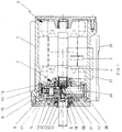
- the single-stage gearbox can be almost completely inserted into the common housing, it can be of sufficient length for good stability. This in turn makes it possible to support the transmission both in the single and in the two-stage version in the common housing. Overall, however, the motor-gearbox unit is still so compact that it can be easily flanged to a gearbox or drive unit on the output side.
- the planetary gear 2 is inserted into the housing 1 and flanged to it via screws 6.
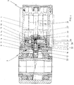
- the single-stage planetary gear 2 can be replaced by a two-stage planetary gear 7 according to FIG. 3 without changing the housing 1.
- the planetary gear 7 is also flanged to the housing 1 by means of corresponding screws 8.
- the cap 10 is inserted into the ring 9 and centrally supports the electric motor shaft which acts as the drive shaft 4 of the transmission.
- the translation takes place in a single-stage gear via planet gears 14 mounted in a planet gear carrier 13.
- the latter mesh in a ring gear 15 incorporated in the interior of the ring 9.
- the output shaft 12 is fixedly connected to the planet gear carrier 13 only one pair of opposing planet gears.
- the planet gear carrier 13 is axially and radially fixed together with the output shaft 12 via an axial-radial bearing combination 22.
- the bearing in the cap 11 takes place via an annular disk 32 screwed to the latter, which is axially enclosed by two axial bearings of the bearing combination 22.
- the cap 10 is fixed axially towards the electric motor 3 via a snap ring 16. Because the rotating gear parts are axially supported against each other, the cap 10 is axial fixed in both directions by being fixed via a further snap ring 17 with respect to the drive shaft 4. The transmission is axially clamped via a threaded ring 18 screwed onto the output shaft 12.
- a flange 26 for attaching a part to be driven by the output shaft 12 can be molded onto the housing cap 11.
- the drive wheel for the part to be driven which can in particular be a gearbox, can be directly connected to the output shaft 12, since the output shaft 12 is mounted in the bearing combination 22 in a sufficiently secure and stable manner.
- FIG. 4 An example of a flanged-on part to be driven is shown in FIG. 4, in which this part is a bevel bevel gear.
- the bevel drive pinion 33 of the flanged angular gear is firmly connected to the output shaft 12 of the motor-gear unit by engaging positively and non-positively in the hollow output shaft 12.
- the drive pinion 5 is provided with a knurled stub shaft.
- the drive shaft 4 has an initially smooth-surface bore with a diameter corresponding to the core diameter of the knurling of the drive pinion 5 - stub shaft.
- the assembly takes place in that the stub shaft is positively pressed into the bore of the drive shaft 4.
- the stub shaft acts practically as a tool for generating the form-fitting counter-shape in the bore of the drive shaft 4.
- the end of the shaft to be inserted into the bore is first provided with a smooth shaft section 20 corresponding to the diameter of the bore.
- An annular groove 21 is provided between the smooth shaft section 20 and the knurled region of the shaft stub, and this has the purpose of receiving material removed from the bore circumference of the output shaft when the shaft stub is pressed in.
- the smooth shaft region 20 can have a shrink fit in the bore of the drive shaft.
- the bore end of the drive shaft 4 is to be kept at a temperature which is higher than that of the pinion 5 when the shaft end of the pinion is inserted.
- the joining technology, with which the pinion 5 is connected to the drive shaft 4, is used in the same way in a two-stage gearbox for joining the two planetary gear carriers 13 and 19.
- the drive pinion 33 of the flanged-on gear can also according to same joining technology to be connected to the output shaft 12.
- an additional lubricating oil reservoir 27 can be provided outside the motor-transmission housing. Since the housing 1 of the motor-gear unit has a cylindrical basic shape, it is possible to attach the additional container to the housing 1 geodetically at the bottom in the area which lies in the space which horizontally recesses due to the cylindrical outer housing shape. This practically does not increase the overall space requirement for such a motor-transmission unit.
- Such an additional lubricating oil container 27 can, for example, be made of plastic and simply clipped onto the housing.
- the connection between the additional container 27 and the interior of the transmission takes place via channels 28, 29 integrated in the housing 1.
- the channel 28 is formed by an annular groove which is molded into the housing and covers the respective gear ring 9.23.
- the interior of the transmission is connected to the channel 28 via a bore 30.
- the annular groove of the housing 1 to form the channel 28 is axially mounted in the housing 1 in such a way that the oil exchange can take place in both a one-stage and a two-stage transmission.
- the oil can flow from the additional container 27 into the interior of the transmission as soon as the oil level drops there, in particular to Oil tracking when the oil level drops due to the circulating lubricating oil.
- the additional lubricating oil container 27 can be equipped with an oil level control device 31. This can be a viewing window or an overall transparent container, each with a scale.
- the additional container 27 can also be provided with a ventilation device at the top in terms of geological attraction.
- the motor-gear unit constructed according to the invention makes it possible to generate relatively high torques from small, high-speed electric motors.
- a one- or two-stage planetary gearbox Through the optional use of a one- or two-stage planetary gearbox, a large range of torques of different sizes can be achieved with the same electric motor on the gearbox output side. Even with a single-stage gear, different gear ratios can be achieved by choosing different gear ratios with the same electric motor.
- Different electric motors with in particular different numbers of poles can also be used in one and the same housing of a motor-gear unit. In particular, DC and three-phase motors can be used.
- the motor-gear unit has a structure that enables both stand and flange mounting.
- the ring gears can remain unchanged by changing only the pinion (s) and the planet gears.
- the drive pinion serving as a sun gear can be used 5 via a needle bearing 34 in the planet carrier 13.
- the radial-axial bearing 22 of the planet gear carrier 13 which is fixedly connected to the output shaft 12, it is then possible to equip the planetary gear 2 with only two planet gears 14 or even with only a single planet gear 14.
- weight compensation must be provided on the planet gear carrier 13.
- planet gears 14 By reducing the planet gears 14 to only two, planet gears 14 of larger diameter can be used with the same construction volume. This increases the gear ratio that can be achieved in one step with the smallest possible construction volume. If only one planet gear 14 is used, no further increase in the transmission ratio is possible, but in this case the costs of the second planet gear can be saved. In addition, the friction occurring in the planetary gear can be reduced.
Applications Claiming Priority (2)
| Application Number | Priority Date | Filing Date | Title |
|---|---|---|---|
| DE4134553 | 1991-10-20 | ||
| DE4134553A DE4134553A1 (de) | 1991-10-20 | 1991-10-20 | Von einem elektromotor angetriebenes planeten-zahnradgetriebe |
Publications (3)
| Publication Number | Publication Date |
|---|---|
| EP0538743A2 true EP0538743A2 (fr) | 1993-04-28 |
| EP0538743A3 EP0538743A3 (en) | 1993-07-07 |
| EP0538743B1 EP0538743B1 (fr) | 1996-09-11 |
Family
ID=6442976
Family Applications (1)
| Application Number | Title | Priority Date | Filing Date |
|---|---|---|---|
| EP92117684A Expired - Lifetime EP0538743B1 (fr) | 1991-10-20 | 1992-10-16 | Groupe de moteur et engrenage planétaire entraîné par moteur électrique |
Country Status (3)
| Country | Link |
|---|---|
| EP (1) | EP0538743B1 (fr) |
| AT (1) | ATE142753T1 (fr) |
| DE (2) | DE4134553A1 (fr) |
Cited By (4)
| Publication number | Priority date | Publication date | Assignee | Title |
|---|---|---|---|---|
| CN102237754A (zh) * | 2010-05-06 | 2011-11-09 | 美闻达传动设备有限公司 | 机电装置 |
| US8841815B2 (en) | 2010-05-06 | 2014-09-23 | The Switch Drive Systems Oy | Electrical machine with guide bars for facilitating assembly and a method for assembling the electrical machine |
| US9464691B2 (en) | 2010-05-06 | 2016-10-11 | The Switch Drive Systems Oy | Electromechanical device |
| US9525320B2 (en) | 2010-05-06 | 2016-12-20 | Moventas Gears Oy | Electromechanical device with included gear stages and internal lubrication system |
Families Citing this family (11)
| Publication number | Priority date | Publication date | Assignee | Title |
|---|---|---|---|---|
| DE4418876A1 (de) * | 1994-05-30 | 1996-01-18 | Klaus Peter Dipl Ing Flamme | Antriebseinheit für einen Linearantrieb mit Hilfe einer Zahnstangen- oder Gliederschubkette in Kompaktbauweise in einem Gehäuse |
| DE4440565A1 (de) * | 1994-11-12 | 1996-05-15 | Gsc Schwoerer Gmbh | Motorgetriebe |
| DE19721646C1 (de) * | 1997-05-23 | 1998-04-16 | Zahnradfabrik Friedrichshafen | Antriebsanordnung mit optimierter Kühlung des Antriebsmotors |
| DE19740552B4 (de) * | 1997-09-15 | 2005-06-16 | Mectrol Gmbh | Getriebeeinheit |
| DE19939608A1 (de) * | 1999-08-20 | 2001-02-22 | Wittenstein Motion Contr Gmbh | Getriebemotor |
| DE10319991B4 (de) * | 2002-05-17 | 2009-12-17 | Sew-Eurodrive Gmbh & Co. Kg | Planetengetriebe |
| DE10316155B4 (de) | 2002-05-24 | 2006-04-20 | Sew-Eurodrive Gmbh & Co. Kg | Welle, Baureihe von Wellen und Verfahren zur Fertigung |
| DE102010025352B4 (de) | 2010-06-28 | 2019-12-24 | Audi Ag | Verfahren zum Herstellen einer elektrischen Maschine eines Kraftwagens |
| DE102013000849A1 (de) * | 2013-01-21 | 2014-07-24 | Sew-Eurodrive Gmbh & Co Kg | Antrieb |
| JP6341768B2 (ja) * | 2014-06-11 | 2018-06-13 | 株式会社 神崎高級工機製作所 | 電動モータ駆動装置 |
| EP4211368A1 (fr) * | 2020-09-14 | 2023-07-19 | Abb Schweiz Ag | Structure d'étanchéité pour protéger un moteur de robot |
Citations (4)
| Publication number | Priority date | Publication date | Assignee | Title |
|---|---|---|---|---|
| CH116668A (de) * | 1925-10-16 | 1926-11-16 | Walter Hofer | Elektromotor mit Reduktionsgetriebe. |
| FR1302143A (fr) * | 1961-09-28 | 1962-08-24 | Siemens Ag | Micromoteur comportant un mécanisme de démultiplication disposé dans son boîtier |
| GB926920A (en) * | 1961-07-21 | 1963-05-22 | Heinrich Desch G M B H | Improvements in or relating to epicyclic gears |
| US4092946A (en) * | 1977-07-25 | 1978-06-06 | Kappas Chris S | Electric trolling motor having planetary gear reduction |
Family Cites Families (11)
| Publication number | Priority date | Publication date | Assignee | Title |
|---|---|---|---|---|
| DE7914728U1 (de) * | 1980-01-03 | Emil Und Adolf Becker Kg, 6349 Sinn | Getriebe für kippbare Behälter | |
| DE7310488U (de) * | 1973-08-16 | Fichtel & Sachs Ag | Planetengetriebe mit gedampft ge lagertem Hohlrad | |
| DE615792C (de) * | 1932-10-20 | 1935-07-12 | Siemens Schuckertwerke Akt Ges | Elektrorolle mit eingebautem Motor |
| US2810844A (en) * | 1954-06-22 | 1957-10-22 | Wayne J Morrill | Gearing arrangement for dynamoelectric machines |
| US3368264A (en) * | 1960-10-05 | 1968-02-13 | Litton Industries Inc | Method of making a gear head for a gear motor |
| US3427484A (en) * | 1965-09-28 | 1969-02-11 | Rockwell Mfg Co | Permanent magnet stator dc motor with hand tool gear train |
| DE2347372A1 (de) * | 1973-09-20 | 1975-03-27 | Zahnradfabrik Friedrichshafen | Formschluessige verbindung |
| SU1170210A2 (ru) * | 1983-05-12 | 1985-07-30 | Litvinskij Igor | Водило планетарной передачи |
| DE8511257U1 (de) * | 1985-04-17 | 1986-08-14 | Robert Bosch Gmbh, 7000 Stuttgart | Zahnrad-Umlaufgetriebe |
| SU1427127A1 (ru) * | 1985-04-26 | 1988-09-30 | Предприятие П/Я Р-6896 | Планетарна беззазорна передача |
| SU1657808A1 (ru) * | 1989-06-22 | 1991-06-23 | Производственное объединение "Уралмаш" | Вертикальный планетарный редуктор |
-
1991
- 1991-10-20 DE DE4134553A patent/DE4134553A1/de not_active Withdrawn
-
1992
- 1992-10-16 AT AT92117684T patent/ATE142753T1/de not_active IP Right Cessation
- 1992-10-16 EP EP92117684A patent/EP0538743B1/fr not_active Expired - Lifetime
- 1992-10-16 DE DE59207106T patent/DE59207106D1/de not_active Expired - Fee Related
Patent Citations (4)
| Publication number | Priority date | Publication date | Assignee | Title |
|---|---|---|---|---|
| CH116668A (de) * | 1925-10-16 | 1926-11-16 | Walter Hofer | Elektromotor mit Reduktionsgetriebe. |
| GB926920A (en) * | 1961-07-21 | 1963-05-22 | Heinrich Desch G M B H | Improvements in or relating to epicyclic gears |
| FR1302143A (fr) * | 1961-09-28 | 1962-08-24 | Siemens Ag | Micromoteur comportant un mécanisme de démultiplication disposé dans son boîtier |
| US4092946A (en) * | 1977-07-25 | 1978-06-06 | Kappas Chris S | Electric trolling motor having planetary gear reduction |
Cited By (7)
| Publication number | Priority date | Publication date | Assignee | Title |
|---|---|---|---|---|
| CN102237754A (zh) * | 2010-05-06 | 2011-11-09 | 美闻达传动设备有限公司 | 机电装置 |
| KR101290359B1 (ko) * | 2010-05-06 | 2013-07-26 | 더 스위치 드라이브 시스템즈 오와이 | 전기기계장치 |
| US8629591B2 (en) | 2010-05-06 | 2014-01-14 | Moventas Gears Oy | Electromechanical device |
| US8841815B2 (en) | 2010-05-06 | 2014-09-23 | The Switch Drive Systems Oy | Electrical machine with guide bars for facilitating assembly and a method for assembling the electrical machine |
| CN102237754B (zh) * | 2010-05-06 | 2014-10-29 | 美闻达传动设备有限公司 | 机电装置 |
| US9464691B2 (en) | 2010-05-06 | 2016-10-11 | The Switch Drive Systems Oy | Electromechanical device |
| US9525320B2 (en) | 2010-05-06 | 2016-12-20 | Moventas Gears Oy | Electromechanical device with included gear stages and internal lubrication system |
Also Published As
| Publication number | Publication date |
|---|---|
| EP0538743B1 (fr) | 1996-09-11 |
| EP0538743A3 (en) | 1993-07-07 |
| ATE142753T1 (de) | 1996-09-15 |
| DE4134553A1 (de) | 1992-03-05 |
| DE59207106D1 (de) | 1996-10-17 |
Similar Documents
| Publication | Publication Date | Title |
|---|---|---|
| EP0538743B1 (fr) | Groupe de moteur et engrenage planétaire entraîné par moteur électrique | |
| DE4421428C1 (de) | Mit einem Elektromotor zu einer Baueinheit verbindbares Planetengetriebe | |
| WO2000009372A1 (fr) | Element d'appui pour remorque de semi-remorque | |
| EP0617214A1 (fr) | Transmission angulaire à axes décalés | |
| DE102017122189A1 (de) | Hebevorrichtung für Fahrzeugheckklappe und Antriebsvorrichtung davon | |
| DE4407714C1 (de) | Elektromotor | |
| DE19729988C1 (de) | Formschlüssige Verbindung zwischen einem aus Kunststoff bestehenden Getriebegehäuseteil und einer Adapterplatte eines Elektromotors | |
| DE4412898A1 (de) | Planetengetriebe mit integriertem Elektromotor | |
| EP0355871B1 (fr) | Unité de galets ou de rouleaux de coincement pour roue libre | |
| DE4102932C2 (de) | Getriebemotor | |
| WO2004077644A2 (fr) | Jeu de pieces detachees pour une serie de motoreducteurs | |
| EP0672812B1 (fr) | Commande de déplacement , notamment pour lêve-glace de voiture | |
| DE19530155A1 (de) | Einzelachsantrieb elektrischer Triebfahrzeuge | |
| DE10258796B3 (de) | Umlaufgetriebe und Mittel zur Montage des Umlaufgetriebes an einem Getriebehänger | |
| EP0601433A1 (fr) | Equipement moteur | |
| DE3641656C2 (fr) | ||
| EP0686788B1 (fr) | Transmission pour moto-réducteur | |
| DE4121299C2 (de) | Getriebegehäuse, insbesondere für Stirnrad/Schneckengetriebe oder Schneckengetriebe | |
| DE2926598C2 (fr) | ||
| DE102005041750B4 (de) | Baukastensystem für Stirnradantriebe unterschiedlicher Leistung für Flurförderzeuge | |
| DE3634894A1 (de) | Antriebsvorrichtung mit einem elektromotor und einem diesem vorgeschalteten getriebe in einem gemeinsamen gehaeuse | |
| DE102010040891A1 (de) | Antriebsvorrichtung zum Antreiben einer Verstellbewegung zweier Fahrzeugteile relativ zueinander | |
| WO1999011949A1 (fr) | Transmission a grand rapport de demultiplication | |
| DE10144803B4 (de) | Planetengetriebe | |
| DE3930940C2 (de) | Dynamoelektrische maschine |
Legal Events
| Date | Code | Title | Description |
|---|---|---|---|
| PUAI | Public reference made under article 153(3) epc to a published international application that has entered the european phase |
Free format text: ORIGINAL CODE: 0009012 |
|
| AK | Designated contracting states |
Kind code of ref document: A2 Designated state(s): AT CH DE FR GB IT LI |
|
| PUAL | Search report despatched |
Free format text: ORIGINAL CODE: 0009013 |
|
| AK | Designated contracting states |
Kind code of ref document: A3 Designated state(s): AT CH DE FR GB IT LI |
|
| 17P | Request for examination filed |
Effective date: 19931122 |
|
| 17Q | First examination report despatched |
Effective date: 19950209 |
|
| RAP1 | Party data changed (applicant data changed or rights of an application transferred) |
Owner name: THYSSEN AUFZUEGE GMBH Owner name: GSC SCHWOERER GMBH |
|
| GRAG | Despatch of communication of intention to grant |
Free format text: ORIGINAL CODE: EPIDOS AGRA |
|
| GRAH | Despatch of communication of intention to grant a patent |
Free format text: ORIGINAL CODE: EPIDOS IGRA |
|
| GRAH | Despatch of communication of intention to grant a patent |
Free format text: ORIGINAL CODE: EPIDOS IGRA |
|
| GRAA | (expected) grant |
Free format text: ORIGINAL CODE: 0009210 |
|
| AK | Designated contracting states |
Kind code of ref document: B1 Designated state(s): AT CH DE FR GB IT LI |
|
| REF | Corresponds to: |
Ref document number: 142753 Country of ref document: AT Date of ref document: 19960915 Kind code of ref document: T |
|
| REF | Corresponds to: |
Ref document number: 59207106 Country of ref document: DE Date of ref document: 19961017 |
|
| ITF | It: translation for a ep patent filed |
Owner name: DE DOMINICIS & MAYER S.R.L. |
|
| GBT | Gb: translation of ep patent filed (gb section 77(6)(a)/1977) |
Effective date: 19961004 |
|
| ET | Fr: translation filed | ||
| PLBE | No opposition filed within time limit |
Free format text: ORIGINAL CODE: 0009261 |
|
| STAA | Information on the status of an ep patent application or granted ep patent |
Free format text: STATUS: NO OPPOSITION FILED WITHIN TIME LIMIT |
|
| 26N | No opposition filed | ||
| PGFP | Annual fee paid to national office [announced via postgrant information from national office to epo] |
Ref country code: GB Payment date: 19980921 Year of fee payment: 7 |
|
| PGFP | Annual fee paid to national office [announced via postgrant information from national office to epo] |
Ref country code: AT Payment date: 19981002 Year of fee payment: 7 |
|
| PGFP | Annual fee paid to national office [announced via postgrant information from national office to epo] |
Ref country code: FR Payment date: 19981020 Year of fee payment: 7 |
|
| PG25 | Lapsed in a contracting state [announced via postgrant information from national office to epo] |
Ref country code: GB Free format text: LAPSE BECAUSE OF NON-PAYMENT OF DUE FEES Effective date: 19991016 Ref country code: AT Free format text: LAPSE BECAUSE OF NON-PAYMENT OF DUE FEES Effective date: 19991016 |
|
| PGFP | Annual fee paid to national office [announced via postgrant information from national office to epo] |
Ref country code: DE Payment date: 19991112 Year of fee payment: 8 |
|
| PGFP | Annual fee paid to national office [announced via postgrant information from national office to epo] |
Ref country code: CH Payment date: 19991116 Year of fee payment: 8 |
|
| GBPC | Gb: european patent ceased through non-payment of renewal fee |
Effective date: 19991016 |
|
| PG25 | Lapsed in a contracting state [announced via postgrant information from national office to epo] |
Ref country code: FR Free format text: LAPSE BECAUSE OF NON-PAYMENT OF DUE FEES Effective date: 20000630 |
|
| REG | Reference to a national code |
Ref country code: FR Ref legal event code: ST |
|
| PG25 | Lapsed in a contracting state [announced via postgrant information from national office to epo] |
Ref country code: LI Free format text: LAPSE BECAUSE OF NON-PAYMENT OF DUE FEES Effective date: 20001031 Ref country code: CH Free format text: LAPSE BECAUSE OF NON-PAYMENT OF DUE FEES Effective date: 20001031 |
|
| REG | Reference to a national code |
Ref country code: CH Ref legal event code: PL |
|
| PG25 | Lapsed in a contracting state [announced via postgrant information from national office to epo] |
Ref country code: DE Free format text: LAPSE BECAUSE OF NON-PAYMENT OF DUE FEES Effective date: 20010703 |
|
| PG25 | Lapsed in a contracting state [announced via postgrant information from national office to epo] |
Ref country code: IT Free format text: LAPSE BECAUSE OF NON-PAYMENT OF DUE FEES;WARNING: LAPSES OF ITALIAN PATENTS WITH EFFECTIVE DATE BEFORE 2007 MAY HAVE OCCURRED AT ANY TIME BEFORE 2007. THE CORRECT EFFECTIVE DATE MAY BE DIFFERENT FROM THE ONE RECORDED. Effective date: 20051016 |