EP0686788B1 - Transmission pour moto-réducteur - Google Patents
Transmission pour moto-réducteur Download PDFInfo
- Publication number
- EP0686788B1 EP0686788B1 EP95108088A EP95108088A EP0686788B1 EP 0686788 B1 EP0686788 B1 EP 0686788B1 EP 95108088 A EP95108088 A EP 95108088A EP 95108088 A EP95108088 A EP 95108088A EP 0686788 B1 EP0686788 B1 EP 0686788B1
- Authority
- EP
- European Patent Office
- Prior art keywords
- gear
- cover
- transmission
- parting line
- housing
- Prior art date
- Legal status (The legal status is an assumption and is not a legal conclusion. Google has not performed a legal analysis and makes no representation as to the accuracy of the status listed.)
- Expired - Lifetime
Links
Images

Classifications
-
- F—MECHANICAL ENGINEERING; LIGHTING; HEATING; WEAPONS; BLASTING
- F16—ENGINEERING ELEMENTS AND UNITS; GENERAL MEASURES FOR PRODUCING AND MAINTAINING EFFECTIVE FUNCTIONING OF MACHINES OR INSTALLATIONS; THERMAL INSULATION IN GENERAL
- F16H—GEARING
- F16H57/00—General details of gearing
- F16H57/02—Gearboxes; Mounting gearing therein
- F16H57/031—Gearboxes; Mounting gearing therein characterised by covers or lids for gearboxes
-
- F—MECHANICAL ENGINEERING; LIGHTING; HEATING; WEAPONS; BLASTING
- F16—ENGINEERING ELEMENTS AND UNITS; GENERAL MEASURES FOR PRODUCING AND MAINTAINING EFFECTIVE FUNCTIONING OF MACHINES OR INSTALLATIONS; THERMAL INSULATION IN GENERAL
- F16H—GEARING
- F16H57/00—General details of gearing
- F16H57/02—Gearboxes; Mounting gearing therein
- F16H57/023—Mounting or installation of gears or shafts in the gearboxes, e.g. methods or means for assembly
-
- F—MECHANICAL ENGINEERING; LIGHTING; HEATING; WEAPONS; BLASTING
- F16—ENGINEERING ELEMENTS AND UNITS; GENERAL MEASURES FOR PRODUCING AND MAINTAINING EFFECTIVE FUNCTIONING OF MACHINES OR INSTALLATIONS; THERMAL INSULATION IN GENERAL
- F16H—GEARING
- F16H57/00—General details of gearing
- F16H57/02—Gearboxes; Mounting gearing therein
- F16H57/033—Series gearboxes, e.g. gearboxes based on the same design being available in different sizes or gearboxes using a combination of several standardised units
-
- F—MECHANICAL ENGINEERING; LIGHTING; HEATING; WEAPONS; BLASTING
- F16—ENGINEERING ELEMENTS AND UNITS; GENERAL MEASURES FOR PRODUCING AND MAINTAINING EFFECTIVE FUNCTIONING OF MACHINES OR INSTALLATIONS; THERMAL INSULATION IN GENERAL
- F16H—GEARING
- F16H57/00—General details of gearing
- F16H57/02—Gearboxes; Mounting gearing therein
- F16H2057/02008—Gearboxes; Mounting gearing therein characterised by specific dividing lines or planes of the gear case
-
- F—MECHANICAL ENGINEERING; LIGHTING; HEATING; WEAPONS; BLASTING
- F16—ENGINEERING ELEMENTS AND UNITS; GENERAL MEASURES FOR PRODUCING AND MAINTAINING EFFECTIVE FUNCTIONING OF MACHINES OR INSTALLATIONS; THERMAL INSULATION IN GENERAL
- F16H—GEARING
- F16H57/00—General details of gearing
- F16H57/02—Gearboxes; Mounting gearing therein
- F16H2057/02086—Measures for reducing size of gearbox, e.g. for creating a more compact transmission casing
-
- F—MECHANICAL ENGINEERING; LIGHTING; HEATING; WEAPONS; BLASTING
- F16—ENGINEERING ELEMENTS AND UNITS; GENERAL MEASURES FOR PRODUCING AND MAINTAINING EFFECTIVE FUNCTIONING OF MACHINES OR INSTALLATIONS; THERMAL INSULATION IN GENERAL
- F16H—GEARING
- F16H57/00—General details of gearing
- F16H57/02—Gearboxes; Mounting gearing therein
- F16H57/023—Mounting or installation of gears or shafts in the gearboxes, e.g. methods or means for assembly
- F16H2057/0235—Mounting or installation of gears or shafts in the gearboxes, e.g. methods or means for assembly specially adapted to allow easy accessibility and repair
Definitions
- the invention relates to a gearbox for a geared motor, consisting of a motor-side drive shaft, an output shaft parallel to this, on which a gearwheel is keyed, a gearbox housing, in its inner transverse wall and in its end wall, recesses are provided for holding shaft bearings, one in Interior of the gearbox arranged and from a cover attached to the end edge of the housing shell to form a sealed parting line, which has a bearing opening for the drive shaft.
- Geared motors are compact drive units for a variety of applications. They consist of a motor that is flanged directly to the gear cover and a gear housing with the corresponding toothing parts.
- the transmission generally has a first stage comprising a motor pinion and an intermediate wheel arranged on the intermediate shaft, and a second stage comprising a drive pinion and a drive wheel arranged on the drive shaft.
- the drive shaft and the intermediate shaft are each mounted in two roller bearings, which are provided on the one hand in the end wall of the transmission housing and on the other hand in a transverse wall in the interior of the transmission.
- the gear cover closes the housing on the motor side and fixes the position from the drive pinion to the idler gear via a centering between the motor and the cover and a fitting device between the cover and the housing.
- the joint between the housing and cover runs at right angles to the shaft axes.
- the gearbox housing In order to be able to mount the drive wheel on the drive shaft between the two roller bearings, the gearbox housing must either have an additional mounting opening (see e.g. DE-B 10 23 646) or there must be sufficient space above the cross wall and between the cross wall and the front wall to allow this To be able to bring the drive wheel into its intended position. This free space required for assembly leads to enlarged external dimensions of the gear housing.
- the object of the invention is to provide a gearbox for a generic geared motor which, with simplified assembly, enables smaller external dimensions.
- the parting line extends at least partially at an acute angle to the longitudinal axis of the transmission.
- the parting line can also have an angled or arcuate shape in the side walls of the housing, as a result of which self-centering between the gear housing and the cover is achieved.
- a recess is formed in the cover, into which the free end of the intermediate shaft engages.
- the transmission according to the invention offers the advantages of a most compact design and high dynamic stability and tightness due to only one joint between the gear housing and the cover. Furthermore, the bearing bores of the housing can be machined in just one set-up and the gear wheels of the output stage are supported in two sections. Since the cover is fixed to the housing by the end of the countershaft, no further centering elements are required. Of particular practical importance is the advantage of the easier assembly of the driven gear compared to known gear designs of the same type.
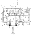
- the transmission shown for a geared motor contains an input or input shaft 1, which can be the output shaft of the motor (not shown) or an intermediate shaft coupled to it.
- This shaft 1 extends through a recess 2 which is formed in the input-side end wall 3 of a cover 4.
- a blind bore 5 is formed on the inside in the end wall 3, which serves to receive the free end of an intermediate shaft 6.
- a peripheral wall 7 adjoins the end wall 3 of the one-piece cover, which ends along a parting line 9 inclined at an acute angle ⁇ to the longitudinal axis of the transmission in FIG. 1.
- the transmission shown has a housing 10 which is made in one piece from an end wall 11 and an end there molded housing shell 12.
- the transmission output shaft 14 is rotatably mounted in a roller bearing 15 and sealed off from the outside by ring seals 16.
- the shaft end 17 is mounted in a further roller bearing 18 which is arranged in a transverse wall 19 which is integrally connected to the housing jacket 12.
- a drive wheel 20 is arranged on the output shaft 14 between the two roller bearings 15 and 18. This gear 20 meshes with the pinion 21 of the intermediate shaft 6.
- the intermediate shaft 6 is mounted on both sides of this pinion 21 in two roller bearings 22, 23, of which one roller bearing 22 in a cutout 24 in the housing end wall 11 and the other roller bearing 23 in a recess 25 are fixed in the transverse wall 19.
- a gear 26 is attached to the intermediate shaft 6, which meshes with the drive pinion 27 of the input shaft 1.
- the cover 4 is - as shown in Fig. 1 - with the formation of e.g. attached by an adhesive sealed joint 9 on the end edge of the housing shell 12 by screws 28, 29.
- FIG. 2 shows the assembly state when the gear 20 is installed.
- the parting line 9 running straight in the side walls of the housing jacket in the drawing may have an angled course, i.e. in the lower part - as shown in FIG. 2 by the dashed line 30 - extend transversely to the longitudinal axis 8 of the transmission or also at an angle of inclination other than the angle ⁇ .
- an arcuate, for example an S-shaped course of the parting line 9 is also possible.
Landscapes
- Engineering & Computer Science (AREA)
- General Engineering & Computer Science (AREA)
- Mechanical Engineering (AREA)
- General Details Of Gearings (AREA)
- Connection Of Motors, Electrical Generators, Mechanical Devices, And The Like (AREA)
- Gear Transmission (AREA)
- Hydraulic Motors (AREA)
- Lens Barrels (AREA)
- Lock And Its Accessories (AREA)
Claims (4)
- Transmission pour moto-réducteur, comportant un arbre d'entrée situé du côté du moteur, un arbre de sortie (14) qui est parallèle à l'axe de ce dernier et sur lequel est montée une roue d'engrenage (20), une transmission intermédiaire (6, 21, 26), un carter de réducteur (10), dans la paroi transversale interne (19) duquel et dans la paroi frontale d'extrémité (11) duquel sont formés des logements pour y placer des roulements, ainsi qu'un couvercle (4) qui est fixé sur l'arête externe du corps du carter (12) en formant un joint de séparation (9) rendu étanche et présentant une ouverture de passage (2) pour l'arbre d'entrée (1),
caractérisée en ce que
le joint de séparation (9) s'étend dans la zone de la roue d'engrenage (20) clavetée sur l'arbre de sortie (14) et est décalée dans cette zone en direction du côté sortie du carter de réducteur (10). - Transmission selon la revendication 1, caractérisée en ce que le joint de séparation (9) s'étend au moins partiellement sous un angle aigu α incliné par rapport à l'axe longitudinal (8) de la transmission.
- Transmission selon la revendication 1 ou 2, caractérisée en ce que le joint de séparation (9, 30) présente une forme anguleuse ou courbe.
- Transmission selon l'une des revendications 1 à 3, caractérisée en ce qu'un logement (5) pour l'extrémité libre de l'arbre de transmission intermédiaire (6) est formé dans le couvercle (3).
Applications Claiming Priority (2)
| Application Number | Priority Date | Filing Date | Title |
|---|---|---|---|
| DE4420305A DE4420305C1 (de) | 1994-06-10 | 1994-06-10 | Getriebe für einen Getriebemotor |
| DE4420305 | 1994-06-10 |
Publications (2)
| Publication Number | Publication Date |
|---|---|
| EP0686788A1 EP0686788A1 (fr) | 1995-12-13 |
| EP0686788B1 true EP0686788B1 (fr) | 1997-10-01 |
Family
ID=6520271
Family Applications (1)
| Application Number | Title | Priority Date | Filing Date |
|---|---|---|---|
| EP95108088A Expired - Lifetime EP0686788B1 (fr) | 1994-06-10 | 1995-05-26 | Transmission pour moto-réducteur |
Country Status (6)
| Country | Link |
|---|---|
| EP (1) | EP0686788B1 (fr) |
| AT (1) | ATE158847T1 (fr) |
| DE (2) | DE4420305C1 (fr) |
| DK (1) | DK0686788T3 (fr) |
| FI (1) | FI952523A (fr) |
| NO (1) | NO952193L (fr) |
Cited By (3)
| Publication number | Priority date | Publication date | Assignee | Title |
|---|---|---|---|---|
| EP1582775A1 (fr) * | 2004-04-02 | 2005-10-05 | Getriebebau Nord GmbH & Co. KG | Carter de transmission |
| WO2006105809A1 (fr) * | 2005-04-01 | 2006-10-12 | Getriebebau Nord Gmbh & Co. Kg | Reducteur a engrenages droits |
| CN103697220A (zh) * | 2013-12-26 | 2014-04-02 | 重庆川仪自动化股份有限公司 | 一种阀门执行器 |
Families Citing this family (6)
| Publication number | Priority date | Publication date | Assignee | Title |
|---|---|---|---|---|
| DE10125148A1 (de) * | 2001-04-23 | 2002-10-24 | Wittenstein Ag | Getriebe, insbesondere Planetengetriebe |
| DE502005006560D1 (de) * | 2005-09-28 | 2009-03-12 | Getriebebau Nord Gmbh & Co Kg | Stirnradgetriebe |
| DE102009026984A1 (de) * | 2009-06-17 | 2011-04-07 | Zf Friedrichshafen Ag | Anordnung mit einem Gehäuse und einem Deckel |
| US11391360B2 (en) * | 2017-10-26 | 2022-07-19 | Auto Ip Llc | Inline gearbox with fast change gearing |
| JP7040327B2 (ja) * | 2018-07-06 | 2022-03-23 | スズキ株式会社 | 自動変速機 |
| EP3926212A1 (fr) | 2020-06-19 | 2021-12-22 | Flender GmbH | Carter d'engrenage échelonnable et gamme de carters |
Family Cites Families (7)
| Publication number | Priority date | Publication date | Assignee | Title |
|---|---|---|---|---|
| CH154897A (de) * | 1931-01-19 | 1932-05-31 | Deutsche Werke Kiel Ag | Mit einem Elektromotor zusammen zu arbeiten bestimmtes Zahnradgetriebe. |
| DE1032635B (de) * | 1953-09-30 | 1958-06-19 | Tacke Maschinenfabrik Komm Ges | Zahnradgetriebe, insbesondere fuer den Zusammenbau mit Elektromotoren |
| DE1023646B (de) * | 1955-04-15 | 1958-01-30 | Baumueller Gmbh A | Getriebemotor |
| US2910882A (en) * | 1957-11-04 | 1959-11-03 | Falk Corp | Housed selective-angle speed-reducer |
| GB1250167A (fr) * | 1968-04-05 | 1971-10-20 | ||
| ES2012680A6 (es) * | 1989-03-06 | 1990-04-01 | Fenollar Manrique Francisco | Reductor de velocidad. |
| DE4025505C3 (de) * | 1990-08-09 | 1997-05-07 | Mannesmann Ag | Getriebegehäuse |
-
1994
- 1994-06-10 DE DE4420305A patent/DE4420305C1/de not_active Expired - Fee Related
-
1995
- 1995-05-24 FI FI952523A patent/FI952523A/fi not_active Application Discontinuation
- 1995-05-26 DE DE59500744T patent/DE59500744D1/de not_active Expired - Fee Related
- 1995-05-26 EP EP95108088A patent/EP0686788B1/fr not_active Expired - Lifetime
- 1995-05-26 DK DK95108088.6T patent/DK0686788T3/da active
- 1995-05-26 AT AT95108088T patent/ATE158847T1/de not_active IP Right Cessation
- 1995-06-02 NO NO952193A patent/NO952193L/no unknown
Cited By (6)
| Publication number | Priority date | Publication date | Assignee | Title |
|---|---|---|---|---|
| EP1582775A1 (fr) * | 2004-04-02 | 2005-10-05 | Getriebebau Nord GmbH & Co. KG | Carter de transmission |
| WO2005095824A3 (fr) * | 2004-04-02 | 2008-12-18 | Getriebebau Nord Gmbh & Co Kg | Transmission par engrenage cylindrique |
| US8087318B2 (en) | 2004-04-02 | 2012-01-03 | Getriebebau Nord Gmbh & Co. Kg | Spur gear transmission |
| WO2006105809A1 (fr) * | 2005-04-01 | 2006-10-12 | Getriebebau Nord Gmbh & Co. Kg | Reducteur a engrenages droits |
| CN103697220A (zh) * | 2013-12-26 | 2014-04-02 | 重庆川仪自动化股份有限公司 | 一种阀门执行器 |
| CN103697220B (zh) * | 2013-12-26 | 2016-04-20 | 重庆川仪自动化股份有限公司 | 一种阀门执行器 |
Also Published As
| Publication number | Publication date |
|---|---|
| FI952523A0 (fi) | 1995-05-24 |
| EP0686788A1 (fr) | 1995-12-13 |
| ATE158847T1 (de) | 1997-10-15 |
| DE59500744D1 (de) | 1997-11-06 |
| FI952523A (fi) | 1995-12-11 |
| DE4420305C1 (de) | 1995-05-24 |
| DK0686788T3 (da) | 1997-10-27 |
| NO952193D0 (no) | 1995-06-02 |
| NO952193L (no) | 1995-12-11 |
Similar Documents
| Publication | Publication Date | Title |
|---|---|---|
| DE4309559B4 (de) | Achsversetztes Winkelgetriebe | |
| EP1266153B1 (fr) | Systeme modulaire d'engrenage | |
| EP0379490B1 (fr) | Agencement d'un train d'engrenages coniques dans un carter d'engrenages | |
| DE4217414C2 (de) | Achslager, insbesondere Radachslager für Kraftfahrzeuge | |
| DE10135602B4 (de) | Baukastengetriebe | |
| EP0686788B1 (fr) | Transmission pour moto-réducteur | |
| DE4102932C2 (de) | Getriebemotor | |
| EP1864036B1 (fr) | Reducteur a engrenages droits | |
| DE10215657B4 (de) | Vorrichtung zum Verbinden einer Längsantriebswelle | |
| DE102005057741A1 (de) | Antriebsvorrichtun für ein bewegliches Fahrzeugteil | |
| EP0716914B1 (fr) | Transmission pour extrudeuse à deux vis | |
| EP1334295B1 (fr) | Differentiel destine a l'entrainement d'axe d'un vehicule | |
| EP1717488A2 (fr) | Transmission à roues coniques et notamment transmission hypoide | |
| DE2902723A1 (de) | Pumpe, insbesondere fluegelzellenpumpe, mit einer gleitlagerung | |
| EP0602357A1 (fr) | Pompe à engrenages | |
| EP1233215B1 (fr) | Garniture mécanique d'étanchéité prête à monter pour l'axe d'une pompe | |
| EP0979945A2 (fr) | Couplage magnetique pour pompe à engrenages | |
| DE3132365A1 (de) | Gleichlaufdrehgelenk | |
| EP0864779A1 (fr) | Différentiel,en particulier pour l'entraínement d'un essieu d'un véhicule à moteur | |
| DE102019118187A1 (de) | Differenzialgetriebe | |
| WO2005121557A1 (fr) | Unite moteur/pompe | |
| DE4121299A1 (de) | Getriebegehaeuse, insbesondere fuer stirnrad/schneckengetriebe oder schneckengetriebe | |
| DE102004049186A1 (de) | Lageranordnung für eine Zwischenwelle | |
| DE102020114800A1 (de) | Lageranordnung | |
| DE3626101A1 (de) | Drehbares antriebsbauteil fuer ein lenkgetriebe, insbesondere fuer kraftfahrzeuge |
Legal Events
| Date | Code | Title | Description |
|---|---|---|---|
| PUAI | Public reference made under article 153(3) epc to a published international application that has entered the european phase |
Free format text: ORIGINAL CODE: 0009012 |
|
| AK | Designated contracting states |
Kind code of ref document: A1 Designated state(s): AT BE CH DE DK ES FR GB GR IE IT LI NL PT SE |
|
| 17P | Request for examination filed |
Effective date: 19960607 |
|
| 17Q | First examination report despatched |
Effective date: 19960722 |
|
| GRAG | Despatch of communication of intention to grant |
Free format text: ORIGINAL CODE: EPIDOS AGRA |
|
| GRAH | Despatch of communication of intention to grant a patent |
Free format text: ORIGINAL CODE: EPIDOS IGRA |
|
| GRAH | Despatch of communication of intention to grant a patent |
Free format text: ORIGINAL CODE: EPIDOS IGRA |
|
| GRAA | (expected) grant |
Free format text: ORIGINAL CODE: 0009210 |
|
| AK | Designated contracting states |
Kind code of ref document: B1 Designated state(s): AT BE CH DE DK FR GB IT LI NL SE |
|
| REF | Corresponds to: |
Ref document number: 158847 Country of ref document: AT Date of ref document: 19971015 Kind code of ref document: T |
|
| ITF | It: translation for a ep patent filed |
Owner name: RACHELI & C. S.R.L. |
|
| REG | Reference to a national code |
Ref country code: CH Ref legal event code: NV Representative=s name: MICHELI & CIE INGENIEURS-CONSEILS Ref country code: CH Ref legal event code: EP |
|
| REG | Reference to a national code |
Ref country code: DK Ref legal event code: T3 |
|
| GBT | Gb: translation of ep patent filed (gb section 77(6)(a)/1977) |
Effective date: 19971003 |
|
| REF | Corresponds to: |
Ref document number: 59500744 Country of ref document: DE Date of ref document: 19971106 |
|
| ET | Fr: translation filed | ||
| PGFP | Annual fee paid to national office [announced via postgrant information from national office to epo] |
Ref country code: SE Payment date: 19980427 Year of fee payment: 4 |
|
| PGFP | Annual fee paid to national office [announced via postgrant information from national office to epo] |
Ref country code: FR Payment date: 19980430 Year of fee payment: 4 |
|
| PGFP | Annual fee paid to national office [announced via postgrant information from national office to epo] |
Ref country code: AT Payment date: 19980506 Year of fee payment: 4 |
|
| PGFP | Annual fee paid to national office [announced via postgrant information from national office to epo] |
Ref country code: BE Payment date: 19980512 Year of fee payment: 4 |
|
| PGFP | Annual fee paid to national office [announced via postgrant information from national office to epo] |
Ref country code: DK Payment date: 19980525 Year of fee payment: 4 |
|
| PGFP | Annual fee paid to national office [announced via postgrant information from national office to epo] |
Ref country code: DE Payment date: 19980729 Year of fee payment: 4 |
|
| PLBE | No opposition filed within time limit |
Free format text: ORIGINAL CODE: 0009261 |
|
| STAA | Information on the status of an ep patent application or granted ep patent |
Free format text: STATUS: NO OPPOSITION FILED WITHIN TIME LIMIT |
|
| 26N | No opposition filed | ||
| PG25 | Lapsed in a contracting state [announced via postgrant information from national office to epo] |
Ref country code: GB Free format text: LAPSE BECAUSE OF NON-PAYMENT OF DUE FEES Effective date: 19990526 Ref country code: DK Free format text: LAPSE BECAUSE OF NON-PAYMENT OF DUE FEES Effective date: 19990526 Ref country code: AT Free format text: LAPSE BECAUSE OF NON-PAYMENT OF DUE FEES Effective date: 19990526 |
|
| PG25 | Lapsed in a contracting state [announced via postgrant information from national office to epo] |
Ref country code: SE Free format text: LAPSE BECAUSE OF NON-PAYMENT OF DUE FEES Effective date: 19990527 |
|
| PG25 | Lapsed in a contracting state [announced via postgrant information from national office to epo] |
Ref country code: LI Free format text: LAPSE BECAUSE OF NON-PAYMENT OF DUE FEES Effective date: 19990531 Ref country code: CH Free format text: LAPSE BECAUSE OF NON-PAYMENT OF DUE FEES Effective date: 19990531 Ref country code: BE Free format text: LAPSE BECAUSE OF NON-PAYMENT OF DUE FEES Effective date: 19990531 |
|
| BERE | Be: lapsed |
Owner name: CARL BOCKWOLDT G.M.B.H. & CO. K.G. GETRIEBEMOTORE Effective date: 19990531 |
|
| PG25 | Lapsed in a contracting state [announced via postgrant information from national office to epo] |
Ref country code: NL Free format text: LAPSE BECAUSE OF NON-PAYMENT OF DUE FEES Effective date: 19991201 |
|
| REG | Reference to a national code |
Ref country code: CH Ref legal event code: PL |
|
| GBPC | Gb: european patent ceased through non-payment of renewal fee |
Effective date: 19990526 |
|
| EUG | Se: european patent has lapsed |
Ref document number: 95108088.6 |
|
| PG25 | Lapsed in a contracting state [announced via postgrant information from national office to epo] |
Ref country code: FR Free format text: LAPSE BECAUSE OF NON-PAYMENT OF DUE FEES Effective date: 20000131 |
|
| NLV4 | Nl: lapsed or anulled due to non-payment of the annual fee |
Effective date: 19991201 |
|
| PG25 | Lapsed in a contracting state [announced via postgrant information from national office to epo] |
Ref country code: DE Free format text: LAPSE BECAUSE OF NON-PAYMENT OF DUE FEES Effective date: 20000301 |
|
| REG | Reference to a national code |
Ref country code: FR Ref legal event code: ST |
|
| REG | Reference to a national code |
Ref country code: DK Ref legal event code: EBP |
|
| PG25 | Lapsed in a contracting state [announced via postgrant information from national office to epo] |
Ref country code: IT Free format text: LAPSE BECAUSE OF NON-PAYMENT OF DUE FEES;WARNING: LAPSES OF ITALIAN PATENTS WITH EFFECTIVE DATE BEFORE 2007 MAY HAVE OCCURRED AT ANY TIME BEFORE 2007. THE CORRECT EFFECTIVE DATE MAY BE DIFFERENT FROM THE ONE RECORDED. Effective date: 20050526 |