EP0534101A1 - Hermetisch dichte Baugruppe - Google Patents
Hermetisch dichte Baugruppe Download PDFInfo
- Publication number
- EP0534101A1 EP0534101A1 EP92113388A EP92113388A EP0534101A1 EP 0534101 A1 EP0534101 A1 EP 0534101A1 EP 92113388 A EP92113388 A EP 92113388A EP 92113388 A EP92113388 A EP 92113388A EP 0534101 A1 EP0534101 A1 EP 0534101A1
- Authority
- EP
- European Patent Office
- Prior art keywords
- carrier
- hermetically sealed
- housing
- housing part
- assembly according
- Prior art date
- Legal status (The legal status is an assumption and is not a legal conclusion. Google has not performed a legal analysis and makes no representation as to the accuracy of the status listed.)
- Withdrawn
Links
- 239000004020 conductor Substances 0.000 claims abstract description 31
- 238000007789 sealing Methods 0.000 claims abstract description 10
- 239000011810 insulating material Substances 0.000 claims description 11
- 238000001465 metallisation Methods 0.000 claims description 6
- 239000011224 oxide ceramic Substances 0.000 claims description 2
- 229910052574 oxide ceramic Inorganic materials 0.000 claims description 2
- 230000005405 multipole Effects 0.000 claims 1
- 230000002093 peripheral effect Effects 0.000 claims 1
- 239000011521 glass Substances 0.000 description 12
- 229910000679 solder Inorganic materials 0.000 description 10
- 238000004519 manufacturing process Methods 0.000 description 2
- 238000005476 soldering Methods 0.000 description 2
- 239000000919 ceramic Substances 0.000 description 1
- 238000010276 construction Methods 0.000 description 1
- 230000001419 dependent effect Effects 0.000 description 1
- 238000005516 engineering process Methods 0.000 description 1
- 230000007613 environmental effect Effects 0.000 description 1
- 230000001939 inductive effect Effects 0.000 description 1
- 238000005259 measurement Methods 0.000 description 1
- 239000000155 melt Substances 0.000 description 1
- 230000008018 melting Effects 0.000 description 1
- 238000002844 melting Methods 0.000 description 1
- 239000002184 metal Substances 0.000 description 1
- 230000001681 protective effect Effects 0.000 description 1
- 238000004804 winding Methods 0.000 description 1
Images
Classifications
-
- G—PHYSICS
- G01—MEASURING; TESTING
- G01C—MEASURING DISTANCES, LEVELS OR BEARINGS; SURVEYING; NAVIGATION; GYROSCOPIC INSTRUMENTS; PHOTOGRAMMETRY OR VIDEOGRAMMETRY
- G01C19/00—Gyroscopes; Turn-sensitive devices using vibrating masses; Turn-sensitive devices without moving masses; Measuring angular rate using gyroscopic effects
- G01C19/02—Rotary gyroscopes
- G01C19/04—Details
Definitions
- the hermetically sealed assembly can be, for example, a dynamically tuned gyroscope or an accelerometer.
- Supply lines to electrical components such as coils or drive motors must be inserted into the housing and signal lines must be led out of the housing.
- each line is passed through the housing individually by means of a glass bushing.
- the glass bushing can either be directly in a breakthrough Be melted housing or have a metallic outer sleeve which is soldered into the housing.
- the electrical conductors to be carried out each sit in these glass bushings, also melted down. These individual glass bushings require a high level of technical effort and extreme care during manufacture.
- the direct melting of glass feedthroughs into the housing can only be carried out by specialized manufacturers.
- the invention has for its object to simplify the hermetic implementation of electrical connections through the housing through a hermetically sealed assembly of the type mentioned, make it safer and cheaper.
- Embodiments of the invention are the subject of the dependent claims.
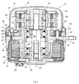
- 10 denotes a housing of a dynamically tuned gyro.
- the housing 10 has a first housing part 12 and a second housing part 14.
- a third housing part 16 connects to the second housing part 14.
- the first housing part 12 is an inverted cup-shaped cover which closes the housing 10 on the upper side in FIG. 1.
- the third housing part 16 is a shell-shaped part, which is hermetically sealed to the second housing part along its edge and closes the housing on the lower side in FIG. 1.
- the second housing part 14 forms a central part of the housing 10 with an essentially cylindrical outer ring 18, an annular disk-shaped intermediate wall 22 running perpendicular to the axis 20 of the housing 10 and an adjoining the inner edge of the intermediate wall 22, coaxial with the outer ring 18 and the axis 20 arranged bearing sleeve 24.
- a stator 26 of a drive motor is seated in the annular space formed by the second and third housing parts.
- a shaft 28 is supported in ball bearings 30 and 32 in the bearing sleeve 24.
- the shaft 28 At its end facing the third housing part 16 and projecting beyond the bearing sleeve 24, the shaft 28 carries a rotor carrier 34.
- the rotor carrier 34 engages over the end face of the bearing sleeve 24 and carries a hollow cylindrical rotor 36 of the drive motor, which coaxially surrounds the bearing sleeve 24.
- the rotor 36 interacts with the stator 26 and drives the shaft 28.
- a gyro rotor 38 is connected to the shaft 28 via a universal joint 40.
- the gyro rotor 38 is thus driven by the drive motor 26, 36 via the universal joint 40 and the shaft 28. Due to the universal joint, however, there are slight deflections of the gyro rotor 38 relative to the Wave 28 possible.
- the universal joint 40 is constructed with cross spring joints. However, such cross spring joints result in a restoring torque which acts on the gyroscopic rotor 38. When the gyro rotor is deflected from its central position, however, a dynamic moment also acts through the gimbal on the gyro rotor 38.
- the restoring torques of the cross spring joints and the dynamic moment of the gimbal are so "dynamically tuned” that the torques exerted thereby on the gyro rotor 38 just compensate.
- the gyro rotor 38 then behaves like a "free" gyro with small deflections
- the gyro is electrically tied to its central position.
- inductive taps are provided, of which only one tap 42 is visible in FIG.
- the tap 42 responds to deflections of the gyro rotor 38 about an input axis perpendicular to the paper plane in FIG.
- another tap is arranged at an angle of 90 ° about the axis 20.
- Torque generators are also provided, by means of which torques can be exerted on the gyro rotor 38. Only one such torque generator 44 is visible in FIG.
- the torque generator 44 also exerts a torque on the gyro rotor 38 about the input axis perpendicular to the paper plane of FIG. 1.
- a second torque generator is arranged at 90 ° to the torque generator 44 at an angle offset from one another.
- the torque generator 44 has flat gate cross coils 46 which are cylindrically curved about the axis 20.
- the gate cross coils 46 sit in a coil holder 48.
- the coil holder 48 projects into a cylindrical air gap 50 formed in the gyro rotor 38.
- the taps 42 are connected "crosswise" to the torque generators 44, the tap signals being amplified by suitable amplifier networks or also being subjected to digital signal processing.
- the tap signal of each tap 42 which responds to the deflection of the gyro rotor 38 about an input axis, is in each case connected to the torque generator 44, which exerts a torque on the gyro rotor 38 about the other input axis perpendicular to this input axis.
- the gyro rotor is "electrically bonded" to the central position.
- the currents that flow in the windings 46 of the torque generators 44 are proportional to the rotation rates around the input axes assigned to the tap.
- the structure described so far is the usual structure of a dynamically tuned gyro.
- the housing 10 of such a gyro is usually hermetically sealed to eliminate disturbing environmental influences and is filled with a protective gas after evacuation.
- electrical connections for driving the motor 26, 36 and for leading in and out of measurement and bond signals must be introduced.
- This hermetic execution of electrical signals takes place in the following way:
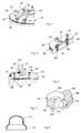
- the carrier 52 consists of machinable oxide ceramic, for example “green ceramic”.
- the carrier 52 lies on an annular surface 54 of the second housing part 14. This annular surface 54 is formed by the surface of the intermediate wall 22 facing the first housing part 12.
- the second housing part 14 has along its circumference adjacent to the ring surface 54 has a projecting edge 58.
- An insulating layer or film 60 lies on the annular surface 54 between the annular surface 54 and the carrier 52.
- the carrier is held in a radial direction between the edge 58 and the coil holder 48.
- the carrier has a first side facing the first housing part 12, the upper side in FIG. 1, and a second side lying on the ring surface 54 of the second housing part, the lower side in FIG.
- a protruding strip 62 running all around is formed on the carrier 52.
- the strip 62 forms a step 64 on its inside.
- the first housing part 12 is placed on the carrier 52 such that the edge 66 of the housing part 12 lies against the step 64 with its outer surface.
- the top 68 of the protruding strip 62 is metallized.
- the "upper" half 70 of the lateral surface of the carrier 52 is metallized.
- the metallized upper side 68 of the strip 62 is hermetically connected to the outer surface of the edge 66 by a solder seam 72.
- the metallized upper half 70 of the lateral surface of the carrier 52 is hermetically connected to the edge 58 by a solder seam 74.
- a hermetically sealed interior 76 is formed, which is delimited by the first housing part 12, the carrier between the inner solder seam 72 and the outer solder seam 74, the second and the third housing part.
- two surface parts 78 and 80 are defined on the first (upper) side of the carrier 52: the surface part 78 lies within the solder seam 72 and adjoins the inner spaces 76.
- the surface part 80 lies outside the solder seam 72 and borders on the outside space or an associated annulus.
- passages 82 are provided in the first surface part 78 from the first to the second side of the carrier 52.
- the bushings 82 are formed by bores, the inner wall of which is provided with a metallization 84.
- bushings 86 are provided in the second surface part 80 of the carrier 52 from the first side to the second side of the carrier 52.
- the bushings 86 are also formed by bores, the inner wall of which is provided with a metallization 88.
- Conductor tracks 90 are provided on the first surface part 78 on the first, upper side, which run out in solder contacts 92. Connections are made from the connecting wires of the electrical components, for example the motor or the tap 42, to the bushings 82 via these conductor tracks 90 and solder contacts 92.
- Conductor tracks 94 are formed on the second side of the carrier 52, which is lower in FIG. 1 and is flat and lies on the insulating layer or film 60. The conductor tracks 94 establish a connection between the metallizations 84 and 88 of the bushings 82 and 86, respectively.
- a multi-core, flat conductor structure in a flexible insulating material strip (“flex connection") 96 is placed like a sleeve.
- the flexible insulating material strip 96 containing the conductor structure contains a cylindrically curved section 98 which surrounds the first housing part 12 like a collar and has contact fingers 102 along its edge 100 which faces the carrier 52 and the second housing part 14.
- the contact fingers 102 are hermetically sealed in the bushings 86 on the second surface part 80 of the carrier 52.
- the second surface part is covered by a cover ring 112.
- the first housing part 12 with the cylindrically curved insulating material strip 98 containing the conductor structure can also be covered by a shielding cap 114, the edge 116 of which on the carrier side is curved outwards and extends over the second surface part 80 Carrier 52 extends.
- FIG. 4 shows a modified version. Corresponding parts are given the same reference numerals in FIG. 4 as in FIGS. 2 and 3.
- annular groove 118 is provided on the first side of the carrier 52 instead of the protruding strip 62.
- the annular groove 118 likewise forms a step 120.
- the first housing part 12 lies against this step 120 with the outer surface of its edge 66.
- Metallization is provided in an annular region of the surface of the carrier 52, which adjoins the annular groove 118 to the outside.
- the carrier 52 is connected to the edge 66 of the first housing part 12 by a solder seam 122.
Landscapes
- Physics & Mathematics (AREA)
- Engineering & Computer Science (AREA)
- General Physics & Mathematics (AREA)
- Radar, Positioning & Navigation (AREA)
- Remote Sensing (AREA)
- Gyroscopes (AREA)
- Casings For Electric Apparatus (AREA)
Applications Claiming Priority (2)
| Application Number | Priority Date | Filing Date | Title |
|---|---|---|---|
| DE19914129917 DE4129917A1 (de) | 1991-09-09 | 1991-09-09 | Hermetisch dichte baugruppe |
| DE4129917 | 1991-09-09 |
Publications (1)
| Publication Number | Publication Date |
|---|---|
| EP0534101A1 true EP0534101A1 (de) | 1993-03-31 |
Family
ID=6440191
Family Applications (1)
| Application Number | Title | Priority Date | Filing Date |
|---|---|---|---|
| EP92113388A Withdrawn EP0534101A1 (de) | 1991-09-09 | 1992-08-06 | Hermetisch dichte Baugruppe |
Country Status (2)
| Country | Link |
|---|---|
| EP (1) | EP0534101A1 (https=) |
| DE (1) | DE4129917A1 (https=) |
Families Citing this family (2)
| Publication number | Priority date | Publication date | Assignee | Title |
|---|---|---|---|---|
| DE9314742U1 (de) * | 1993-09-29 | 1994-08-04 | Siemens AG, 80333 München | Tauchdicht abzudichtendes Gehäuse |
| DE19711278B4 (de) * | 1997-03-18 | 2009-06-04 | Deutsche Telekom Ag | Gerätegehäuse |
Citations (2)
| Publication number | Priority date | Publication date | Assignee | Title |
|---|---|---|---|---|
| DE1791024B1 (de) * | 1967-09-01 | 1971-05-19 | Lucas Industries Ltd | Leiterplatte und verfahren zu deren herstellung |
| EP0444445A1 (de) * | 1990-02-20 | 1991-09-04 | Bodenseewerk Gerätetechnik GmbH | Dynamisch abgestimmter Kreisel |
Family Cites Families (1)
| Publication number | Priority date | Publication date | Assignee | Title |
|---|---|---|---|---|
| DE3402256A1 (de) * | 1984-01-24 | 1985-08-01 | Brown, Boveri & Cie Ag, 6800 Mannheim | Gehaeuse zur aufnahme elektronischer bauelemente |
-
1991
- 1991-09-09 DE DE19914129917 patent/DE4129917A1/de active Granted
-
1992
- 1992-08-06 EP EP92113388A patent/EP0534101A1/de not_active Withdrawn
Patent Citations (2)
| Publication number | Priority date | Publication date | Assignee | Title |
|---|---|---|---|---|
| DE1791024B1 (de) * | 1967-09-01 | 1971-05-19 | Lucas Industries Ltd | Leiterplatte und verfahren zu deren herstellung |
| EP0444445A1 (de) * | 1990-02-20 | 1991-09-04 | Bodenseewerk Gerätetechnik GmbH | Dynamisch abgestimmter Kreisel |
Also Published As
| Publication number | Publication date |
|---|---|
| DE4129917C2 (https=) | 1993-06-17 |
| DE4129917A1 (de) | 1993-03-11 |
Similar Documents
| Publication | Publication Date | Title |
|---|---|---|
| DE60005118T2 (de) | Durchführvorrichtungen | |
| DE2309825C2 (de) | Durchführung in Metall-Glas-Einschmelztechnik | |
| DE2913985A1 (de) | Implantierbares reizstromgeraet | |
| DE3237196C2 (de) | Synchronkleinstmotor | |
| DE3642770A1 (de) | Induktivgeber | |
| DE3447826C2 (de) | Elektro-Außenläufermotor | |
| DE3405786A1 (de) | Transformator mit gleichrichter | |
| EP0272131A3 (en) | Hv cables | |
| DE2609884A1 (de) | Wellenfilter mit elastischer wellenausbreitungsflaeche | |
| DE3516213C2 (https=) | ||
| EP0534101A1 (de) | Hermetisch dichte Baugruppe | |
| DE19523977A1 (de) | Microchip-Sicherung | |
| EP0003034A1 (de) | Gehäuse für eine Leistungshalbleiterbauelement | |
| EP3118946A1 (de) | Schleifring sowie schleifringeinheit mit einem schleifring | |
| DE2936928C2 (de) | Teil der äußeren Wand eines Gerätes bildendes Batteriegehäuse | |
| EP1147534B1 (de) | Entladungslampe | |
| DE19756575B4 (de) | Elektromotor | |
| WO1991009408A1 (de) | Drehwinkel-potentiometer | |
| DE3335530A1 (de) | Gasdichtes gehaeuse | |
| DE1938229A1 (de) | Elektrischer Kleinmotor | |
| DE3604583A1 (de) | Miniaturmotor | |
| DE3620111A1 (de) | Hochfrequenz-koaxialbuchse | |
| EP0526684A2 (de) | Lithium-Jod-Batterie | |
| JPS6130014A (ja) | ロ−タリ−トランスの巻線法 | |
| DE3433060A1 (de) | Drehzahlsensor fuer elektromotoren |
Legal Events
| Date | Code | Title | Description |
|---|---|---|---|
| PUAI | Public reference made under article 153(3) epc to a published international application that has entered the european phase |
Free format text: ORIGINAL CODE: 0009012 |
|
| AK | Designated contracting states |
Kind code of ref document: A1 Designated state(s): DE FR GB |
|
| 17P | Request for examination filed |
Effective date: 19930811 |
|
| 17Q | First examination report despatched |
Effective date: 19940913 |
|
| STAA | Information on the status of an ep patent application or granted ep patent |
Free format text: STATUS: THE APPLICATION IS DEEMED TO BE WITHDRAWN |
|
| 18D | Application deemed to be withdrawn |
Effective date: 19950715 |