EP0533177B1 - Verfahren zur Rauschdetektion und Rauschunterdrückung - Google Patents
Verfahren zur Rauschdetektion und Rauschunterdrückung Download PDFInfo
- Publication number
- EP0533177B1 EP0533177B1 EP92115956A EP92115956A EP0533177B1 EP 0533177 B1 EP0533177 B1 EP 0533177B1 EP 92115956 A EP92115956 A EP 92115956A EP 92115956 A EP92115956 A EP 92115956A EP 0533177 B1 EP0533177 B1 EP 0533177B1
- Authority
- EP
- European Patent Office
- Prior art keywords
- noise
- contour
- data
- erasing
- region
- Prior art date
- Legal status (The legal status is an assumption and is not a legal conclusion. Google has not performed a legal analysis and makes no representation as to the accuracy of the status listed.)
- Expired - Lifetime
Links
Images


Classifications
-
- H—ELECTRICITY
- H04—ELECTRIC COMMUNICATION TECHNIQUE
- H04N—PICTORIAL COMMUNICATION, e.g. TELEVISION
- H04N1/00—Scanning, transmission or reproduction of documents or the like, e.g. facsimile transmission; Details thereof
- H04N1/40—Picture signal circuits
- H04N1/409—Edge or detail enhancement; Noise or error suppression
Definitions
- This invention relates to noise detection and erasing methods which can detect and erase at a high speed and a high efficiency noises contained in binary images which have been read by an input means such as a scanner and digitized, and the method can easily change the levels of erasing such noises.
- the first system for erasing noises from images which judges whether an objective is a noise or not by reading an objective pixel and neighboring pixels, and conducting logical operations of the objective pixel with the neighboring pixels.
- the first system consecutively cuts out two dimensional local regions from a two-dimensional binary black/white pattern which is the object of processing, and conducts spatial logic processing of the logical state of the central pixel and that of the neighboring pixels so as to extract noises.
- the first system judges whether the objective pixel is a noise or not from the relation of the pixel with the neighboring pixels, it takes much time to erase the noises from all the images. Moreover, the system can judge the noises only in the unit of a pixel, and cannot erase linear noises which consist of pixels more than two.
- Japanese Patent Publication 9389/1990 disclosed another system (hereinafter refer to as "the second system") which conducts the noise judgement of the above first system in the unit of a line, and erases a noise if there is one (in this case, a noise means the state of "1"). More particularly, the second system stores the objective image for each line, stores the data of each line by shifting to the right, and stores the data of each line by shifting to the left so as to erase minute isolated points by logical operation of the data in the unit of a line.
- the second system Since the second system uses the data on lines before and after an objective line, it can operate at a speed faster than that of the first system, but its operation is limited to the erasing of the minute isolated points.
- the second system is also problematic in that the control system becomes quite complicated. Even though the second system judges the noises in the unit of a line, a line comprises pixels and when realized in a computer software, the system is not practical in terms of processing time. For example, when a mechanical sheet for print is read in the system, the noises caused by the mounting lines become laterally or longitudinally elongated noises comprising plural pixels, which cannot be erased by either the first or the second system.
- the present invention was conceived to overcome the above defects of the prior art and aims to provide an improved method which can erase arbitrary noises with basically plural pixels.
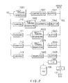
- FIGs.1A and 1B show an image processing system in block diagrams to which this invention method is applicable.
- Originals such as image pictures, characters, figures and mechanical sheets are read out by an input unit 1 such as a scanner, and thus obtained density data DD of the images are inputted in an input controller 100.
- the input density data DD are converted into halftone dots by a halftoning circuit 102 in the input controller 100 via a CPU 101 contained therein, compressed by a compression circuit 103, temporarily stored in a buffer memory 104, and transferred to a file server 200 via an SCSI bus to be stored in a magnetic tape 210, or hard discs 220, 221 ⁇ ⁇ .
- the input controller 100 has a local disc (hard disc) 105 for temporarily storing the data.
- the file server 200 includes a CPU 201, and is connected to other devices via interfaces 202 through 205.
- Code information CD such as characters obtained from an edition input unit 2 such as a word processor and a composer are read out from a floppy disc 3 after temporarily stored therein, and inputted to a work station 300.
- Each work station 300 has plural sets of terminals including a CRT 301 as a display means, a keyboard 302, a mouse 306 and a digitizer 303 as input operation means, a hard disc 304 and a floppy disc 305 as memory means.
- Each work station 300 is connected to the file server 200 via ETHERNET.
- the image data, frame data and image data for contour display which are obtained from the input controller 100 and thinned for CRT display are stored in the magnetic tape 210 or hard discs 220, 221 ... together with the high density data for image output which are not thinned.
- the thinned data are read out via the SCSI bus, and transferred to the work station 300 via interfaces 204 and 202 while control commands from the input controller 100 are transferred via an auxiliary data line 4 to the interface 200 of the file server 200.
- the file server 200 is further connected to an image setter 400.
- the image setter 400 includes a CPU 401, is connected to an auxiliary data line 5 of the file server 200 via the interface 402, and is connected to the SCSI bus via the interface 403.
- the image setter 400 further includes a sequencer 410 and a buffer memory 411 which stores necessary data, and is connected to a high quality image output unit 10 for outputting high quality images and a laser beam printer (LBP) 11 for outputting images of relatively low quality images.
- the hard discs 220, 221, ... ... store in advance fixed data (bit map data) such as a logo, a crest and halftone dots and vector font data for character output.
- the input unit 1 digitizes image pictures (halftone images), line drawings, and character images (binary images) into density data (8 bits/ pixel).
- the signals of pictures inputted in 8 bits/pixel are converted into halftone dots by the input controller 100 to generate information of 4 bits/ pixel.
- the binary images are converted into information of 1 bit/pixel.
- Characters are inputted from the work station 300 in codes, but sometimes are inputted in images from the input unit 1. When inputted as the images, the characters are also treated as images (bit map data). All the images are outputted by the image setter 400, but since all the codes and vector information are converted into the bit map data by the image setter 400, the term "image output" is used herein to express the output of the bit map data.
- the input controller 100 is described in more detail referring to FIG.2.
- the input controller 100 is adapted to process the density data DD inputted from the input unit 1 to generate five sets of data concurrently; i.e. high density data for the high quality image output unit 10, data for the laser beam printer 11, two types of data for display on the CRT 301 of the work station 300, and image data of a density low enough to express the contour.
- high density data for the high quality image output unit 10 are converted into the halftone dots by a halftoning circuit 1021, compressed by a compression circuit 1031, and temporarily stored at a buffer memory 1041.
- the density data DD are thinned (110) at a given interval (e.g. 1/3), and the obtained lower density data are converted into the halftone dots by a halftoning circuit 1022, compressed by a compression circuit 1032, and temporarily stored at a buffer memory 1042.
- the density data DD are thinned at a given interval and converted into the halftone dots by halftoning circuits 1023 and 1024, temporarily stored respectively at buffer memories 1043 and 1044.
- image data are thinned (113) after they are processed for Laplacian operation or unsharp mask processing to express the contour data, and then binarized at a binarizing circuit 1025 to be temporarily stored in a buffer memory 1045.
- the CPU 101 communicates with the input unit 1 via a data lines (not shown) and with the file server 200 via the auxiliary data line 4 and a dual port RAM (not shown).
- the CPU 101 sets data necessary for respective circuits as shown in FIG.2, stores the set data in the local disc 105, and further sets values related to auxiliary scanning.
- the density data DD from the input unit 1 are inputted in the unit of one line and synchronized by respective circuits shown in FIG.2 to be stored in the buffer memory 104 (1041 through 1045).
- the CPU 101 checks the switching of the SCSI bus and of the output buffer memory 1041 for the data compression, and presence/absence of error information from various circuits.
- the data once stored in the buffer memory 104 and the local disc 105 are sorted in accordance with the command from the CPU 101 and outputted to the SCSI bus outside of the system.
- the structure of the file server 200 is shown in FIG.1B.
- the file server 200 functions to manage and share common files and to control communications between networks and among units. More particularly, the file server 200 manages files of the hard discs (220, 221 ... ... ) and the magnetic tape 210 via the SCSI bus, functions as a software interface with the work station 300 via an ETHERNET, serves for file management information for the input controller 100 and the image setter 400, and executes utility functions for the file management via the SCSI bus including for example, registration of fonts and garbage collection of the SCSI discs.
- font registration There are two types of font registration; one is the registration of fonts included in the system which is executed by storing the vector fonts prepared by an outside font formation system in the hard disc of the image processing system in the form of magnetic tapes, and the other is the registration of fonts which are not included in the system. In this case, fonts prepared by other systems are registered in the system in the form of a floppy or a magnetic tape.
- the file server 200 serves for the data transmission among the work station 300, the input controller 100 and image setter 400 and stores the data therefor, while the input controller 100 receives necessary information from the file server 200 for securing or deleting various files via the auxiliary data line 4 and the dual port RAM.
- information such as file name and file capacity, etc. should be transferred to the file server 200, and the hard discs 220, 221 ... on the SCSI bus should be accessed. This makes the file server 200 to start directory communication and disc area management.
- the file server 200 transfers the file data to the work station 300 via the ETHERNET or receives data from the work station 300.
- the file server 200 manages the hard discs on the SCSI bus (220, ... ) and the magnetic tapes 210 and renews necessary information such as directory. It also receives the commands for the image setter 400 and for the magnetic tape 210 and performs services according to the commands. It transmits given commands to the image setter 400 via the auxiliary line 5 and the dual port RAM, and transmits file management information to respond to the request from the image setter 400 so that the image setter 400 directly makes access to the disc data on the SCSI bus. Further, the utility information related to the image processing system as a whole including font information and common files of the system are managed in the hard discs 220, 221, ... ... on the SCSI bus.
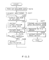
- Step S310 The document data edited and storred by the edition/input unit 2 are read out from the floppy disc 3 (Step S310), and the code information CD of the document data is converted in terms of data format (Step S311).
- the content of the document is displayed in the unit of one page on the CRT 301 (Step S312), and the output positions of the images read out from the mechanical sheet or the like are designated with the mouse 306, a keyboard 302 and a digitizer 303 (Step S313) and page description data in the unit of one page with the frame of the mechanical sheet are formed (Step S314).
- Such data are prepared for all the pages (Step S315), and the layout for the printing block are instructed from the keyboard 302 (Step S316).
- the page description data with layout are prepared (Step S317).
- the prepared data are transferred to the file server 200 (Step S318), and the image setter 400 is instructed to output images, whereupon the operation is completed (Step S319).
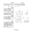
- Step S330 The image data which have been thinned from the hard discs 220, 221, ... of the file server 200 are read-in (Step S330), the document data from the floppy disc 3 are read-in (Step S331), the necessary information are displayed on the CRT 300 of the work station 300, and layout of images, texts, and frames for each page is arranged using the mouse 306, the keyboard 302 and the digitizer 303 (Step S332).
- a particular type of page composition which is stored in advance is selected from the keyboard 302 (Step S333), and pages with the selected composition (e.g.
- a through D in the FIG.4) are displayed on the CRT 301 with pagination (Step S334).
- the page compositions are stored with pagination in advance with due consideration of the folding of sheets at the time of book binding such as 4 pages in A4 size or 8 pages in A5 size.
- a page composition with pagination is displayed (for example, in B in FIG.4, "1", “8", "5" and "4").
- the content such as pattern and character images are not displayed. Instead, bit map data are generated and outputted by the image setter 400 based on the page descriptive data (Step S335).
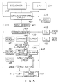
- FIG.5 shows an example of the structure of the image setter 400 wherein the sequencer 410 is connected to a CPU bus 412 and an image data bus 413 as well as to a logical operational circuit 420 and a first memory 421.
- the CPU bus 412 is connected to the main memory 430 for the CPU 401.
- a common memory 424 is connected between the CPU bus 412 and the image data bus 413, and the outputs from the interfaces 402 and 403 are inputted to the CPU bus 412.
- the CPU bus 412 and image data bus 413 are connected a buffer memory 433, an expander 440, and a third memory 423 as well as a buffer memory 434, a raster image converter 431 and a second memory 422 and a buffer memory 435 and an output control circuit 436.
- the CPU bus 412 is connected with a vector font memory 432 while the output control circuit 436 is connected with the high quality image output unit 10 and the laser beam printer 11 via the output buffer memory 436A.
- the vector font memory 432 stores the vector fonts necessary for producing a character bit map by the raster image converter 431.
- the vector fonts are usually stored in the hard discs (220, 221, ...
- a request for a command is outputted from the file server 200 via the auxiliary data line 5 to the image setter 400 using the file names in the hard discs 220, 221, ... as parameters.
- the files are written with specifications to be outputted.
- the specifications are sequentially read, and the code data and the compression data are address-calculated for each unit image, and the addresses are over-processed repeatedly by the logical operation.
- the result of the processing is stored in the first memory 421.
- the image setter 400 calls up parameter file via the SCSI bus and repeats the operation.
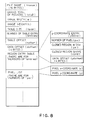
- Step S400 information such as the character code, the position, the type face and the size are inputted via the SCSI interface 403 (Step S400), converted into raster images at the raster image converter 431 via the buffer memory 434 (Step S401) and stored in the second memory 422 (Step S402).
- the compressed image data are inputted via the SCSI bus and the interface 403 (Step S403), expanded by the expander 440 to be restored after passing through the buffer memory 433 (Step S404) and stored in the third memory 423 (Step S405).
- the bit map data such as logo sorted in the hard discs 220, 221, ⁇ are inputted via the interface 403 (Step S406) and stored in the common memory 424 (Step S407). All the data stored in the second memory 422 through the common memory 424 are the bit map data to be logically operated by the logical operational circuit 420 via the CPU 401 (Step S410). The data logically operated for syntheses or editing of pictures or texts, or for the image processing are stored in the first memory 421 (Step S411). After the data are stored in the first memory 421, whether or not an alternation or addition is necessary is judged (Step S412) and operations mentioned above are continued until all the logical operations including alternation and modification are completed.
- the logical operational circuit 420 executes in cooperation with the CPU 401 logical operaions of the bit map data produced from the code data such as the characters, the bit map data obtained by expanding the compacted image data and the sum, the product, the difference, the exclusive-OR, etc. of the bit map data to produce the image information to be outputted to the high quality image output unit 10 or the laser beam printer 11.
- the function of noise detection according to this invention comprises region definition which is to be described hereinafter and the following Steps 1 and 2.
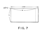
- the bit map or the object of the noise detection is defined by width (w), height (h), number of words/line (ww) and the head address (adrs) as shown in FIG.7.
- Each parameter means the following.
- the above region definition is conducted in the memory of the work station for each parameter, the closed region list of the first Step 1 is formed, and then the noise list is formed in the Step 2.
- the entry table of the y-coordinates is sorted as "ycoord”.
- the noise table need not be sorted by the upper-left coordinates or "lx”.
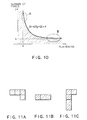
- Criteria for the noise judgement in the Step 2 above include the number (pix) of pixels in a closed region, the flattening obtainable from the ratio of length against width of the closed region and the curvature r as shown in FIG. 10.
- the horizontal axis x represents the flattening which is obtained by (the short side/the long side) ⁇ 100 %.
- FIG.11A has the length "2" for the short side and "3" for the long side
- FIG.11B has the length "1" for the short side and "3" for the long side
- a hyperbola of the curvature r with asymptotes a and b is established with respect to the orthogonal axes of the flattening (x) and the number of pixels (y) as shown in FIG.10.
- the hatched area is judged as noises. This method realizes effective erasing of the noises because the thin and elongated noises such as traces of mounting concentrate in areas near the area A while minute noises such as dust concentrate in areas near the area B.
- the form of the hyperbola may suitably be changed simply by inputting the values a and b and the curvature r which determine the asymptotes. Because the unit system of the coordinates of the noise list is the unit system of output pixels, it is necessary to designate pixel density of the bit map with which the noise is detected. According to this invention method, the pixel density of the bit map is expressed in i bit pixel/mm, and the density of the output pixel in o bit pixel/density.
- the above explains the outline of the operations according to this invention method. Each operation will now be described in more detail.
- the basic condition of a region are the contour tracing by extraction of 8 pixels in the neighborhood of an objective pixel. To facilitate the extraction, the whole images are copied in a region larger than the object region. To simplify the operation, one line each is added at the top and the bottom. Then, 32 bits (one long word) are added to the left side and 0 to 31 bits to the right side so that the data amount of one line becomes a multiple of an integer of a long word (4n bytes).
- the original region S (adrs, w, h, ww) is copied in a modified region S' (src, w, h, 1ww). The added regions are all cleared zero.
- a region S" (src', w, h, 1ww) with the origin set at the position (32, 1) in the modified region S' is defined and is processed subsequently as the original region S.
- bit map data of images are made in the unit of a word (16 bits) in order to be displayed on the CRT 301, it is more efficient to use a bit map in the unit of a long word (32 bits) on a CPU with 32 bits.
- the bit map data processing is hereafter treated as the long word bit map processing. It is therefore necessary to swap the long words of higher orders with those of lower orders in the original region S.
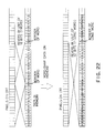
- FIG.22 shows the word swapping of the data in the memory.
- contour bit map W (dst, w, h, 1ww) is formed from the bit map image data S (src, w, h, 1ww) shown in FIG.23.
- a contour region W of the same size as the original region S is secured as shown in FIG.24, and the original region S is copied into the contour region W.
- the original region S is shifted to the right by one bit and AND-copied into the contour region W as shown in FIG.25.
- the one pixel on the left side of the region W is made white.
- the hatched portion of the contour region W is the region for AND-operation.
- the original region S is then shifted to the left by one bit and AND-copied into the contour region W, and one pixel on the right side of the region W is made white as shown in FIG. 26.
- a region W2 of the same size as the original region W is secured as shown in FIG.27, and the region W is copied into the region W2.
- the region W2 is shifted upward by one line and AND-copied into the contour region W as shown in FIG.29, and one line at the bottom of the contour region W is made white.
- the region W2 is shifted downward by one line and AND-copied into the region W2, and one line on the upper edge of the contour region W is made white.
- the region of the region W2 is then released, and the original region S is copied by exclusive-UR (EX-OR) into the contour region W.
- EX-OR exclusive-UR
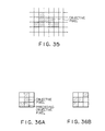
- the data on the 8-neighboring pixels mean the data on the region of 3 ⁇ 3 pixels around an objective pixel.
- chain codes "0" through “7” are assigned to the 8-neighboring pixels surrounding an objective pixel CP as shown in FIG.31.
- pixels are allocated to bits in a word as shown in FIG.32. In FIG.32, the bits in the hatched portion are all zero.
- the objective pixel is expressed by the structure like a formula (1) below instead of the coordinates (x, y) in order to increase the speed.
- “adrs” denotes the address (pointer) of a long word including the objective pixel
- "boff” the offset in the long word of the objective pixel
- “1ww” the number of the long words in one line of the region, or the difference expressed in long word between the objective pixel and the long word including the pixels in the neighborhood.
- the contour tracing is a general method of assigning the chain codes "0" to "7" to the 8-neighboring pixels surrounding the objective pixel CP. According to this invention, however, as the method is quite special in that tracing is conducted for the contour of the original bit map only after the contour pixels are found by scanning the contour image, the method requires special steps to be taken for the first point.
- the chain codes "0" to "7” are assigned to the 8-pixels surrounding the objective pixel CP. For instance, in FIG.31, if the immediately proceeding objective pixel existed in the direction of the chain code "3", the pixels of the chain codes are examined in the order of "4, 5, 6, 7, 0, 1, 2, and 3", and the pixel which is found to be the first black pixel becomes the next objective pixel. In the case of FIG.34A, the next objective pixel is in the direction of the chain code "6" while in the case of FIG.34B, the next objective pixel is in the direction of chain code "3" again.
- the pixel in the chain code "4" is virtually selected as the immediately preceding objective pixel in order to obtain the next objective pixel.
- the next objective pixel becomes the chain code "5" (correctly, the pixel of the chain code "7") to mislead the processing.
- the next objective pixel must be located by the following flow of steps only in the case of the starting point. If “the pixel on the left of the objective pixel is black”, then “examine the pixels from the one on the left of the objective pixel counterclockwise, and scan until a white pixel is found.
- a table for retrieval should be prepared in advance in order to increase the speed of the steps to obtain the data on the 8-neighboring pixels and the chain code of the next objective pixel on the basis of the immediately preceding objective pixel.
- This invention method requires two tables as it involves two different procedures for the starting point and those other than the starting point. The tables to prepare are
- the object of designating the image frame is to erase the noises from the entire image data at a given level, and this function allows a frame in which line images are arranged can be designated for the noise erasing.
- the images may be mechanical sheet images or part images.
- the noise level is determined by the image number sheets, and when a completion is instructed, the image data are processed for the noise erasing after closing the sheet. Then, the images from which noises have been erasing at the designated level are displayed.
- the items set for the noise erasing are noise size and noise shape, and can be settled only when the noise mode is switched "OFF". By similar operations, the frames on which images have already been arranged may be changed in the level.
- the sequence of the operation will be as follows: an image arrangement command is first selected, whereby the image arrangement sheet as shown in FIG.37 is displayed. Then, the image number of the sheet is designated, "YES" is selected on the noise erasing items, and the predetermined positions, the noise size, and the noise shape are respectively' designated. Lastly, the completion of the sheet is instructed, to display the images arranged in the frame as shown in FIG.38 which have been processed for the noise erasing as instructed. When the images of the number designated do not satisfy the conditions of
- Designation of a rectangle region is intended for the noise erasing of a part of image data at a given level. More particularly, the region for the noise erasing is designated in a regular rectangle; the position and size of a region are set arbitrarily. However, the shape is limited to regular rectangles.
- the images to be processed may be either the mechanical sheet images or the part images. Frames that are selected when the noise mode is selected alone can be processed, and the processing is possible only when the noise mode is "ON".
- the noise erasing designated in terms of an area has a higher priority than that designated in terms of an image frame.
- the area A in FIG.39 indicates that frame of the mechanical sheet is designated for the noise erasing of level "3", while the area B indicates that a rectangular area is designated for the noise erasing of level "1". In other words, it means that the noise erasing of level "3" is to be executed in the outer portion, and the noise erasing of level "1" is to be executed in the inner portion.
- the areas overlap the overlapped areas are subjected to the noise erasing under OR-conditions at levels designated for respective areas. More particularly, in FIG.40, the area C is designated for the noise erasing of level "1" while the area D is designated for the noise erasing of level "3".
- the portion with oblique lines from the right to the left is processed for the noise erasing at the level "1" while the portion with the oblique lines from the left to the right is processed for the noise erasing at level "3".
- the overlapping area is processed for the noise erasing at levels "1" and "3".
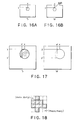
- FIG.41A An image or the objection noise erasing is arranged and the frame thereof is selected and designated as shown in FIG.41A.
- noise mode When the noise mode is switched "ON", noises in the selected image are displayed in red color as shown in FIG.41B. Noise here means what are processed as noise by the previous operations.
- a regular rectangle command is selected to surround by designating two points the portion where the image is deteriorated as the result of previous commands or the portion from which any noise is so far not erased. This produces a designated rectangle.
- the structure display is turned “ON”
- the component line of a frame is displayed in a broken line as exemplified by the line L1 of FIG.41C.
- the noise size of the produced frame is identical to the objective frame of the noise erasing selected as above.
- the noise level command is issued and the noise size of the frame is changed. Then, the portion newly judged as noise is displayed in red color as shown in FIG.41D. In this case, as a period has been deteriorated and erased, an instruction is issued to decrease the noise level.
- the instruction with the rectangle/point eraser command is used to erase all the portions where image data exist.
- a command by the prior art rectangle/point eraser is issued and all the black pixels inside the frame designated by the command are all erased unconditionally.
- the noise size cannot be changed after the formation.
- the target may be a mechanical sheet image or a part image; however, it is the frame which is being selected when the command to turn "ON" the noise display is issued. The operation is possible only when the noise mode is switched "ON".
- a frame in which exists the objective image for the noise erasing is selected and designated as shown in FIG.42A.
- noises in the selected image are displayed in red color as shown in FIG.42B, and a rectangle/eraser command is selected.
- a rectangle/eraser command is selected.
- two points so as to surround the area to be erased with a rectangle as shown by L2 in FIG.42C.
- a rectangle as designated is formed, and the inside thereof is displayed in red color as shown in FIG.42D.
- the structure display is switched "ON"
- the component line of the frame is displayed with a broken line. All the black pixels inside the produced frame become subjected to erasing unconditionally. In the case of a point eraser, the same operation is executed.
- the display of the noise erasing region displays the component lines when the target area for the noise erasing is to be deleted or the level of the noise erasing is to be changed.
- the noise erasing region is displayed in a broken lines. More specifically, a frame in which am objective image for the noise erasing is arranged is selected, and the noise mode is switched “ON”. Then, the structure display is turned “ON”, and a noise erasing area is displayed in a broken line. If the structure display has already been turned “ON” when the noise mode is turned “ON”, it is not necessary to turn “ON” the structure display. If the component line display is not needed, the structure display is turned “OFF”.
- the rectangle/point eraser displays the component lines when a target for erasing with the eraser is to be selected.
- the component lines are displayed in broken lines when both the noise mode and the sturcture display are turned “ON”.
- a frame in which the objective image for the noise erasing is arranged is selected, and the noise mode is switched “ON”.
- the structure display is turned “ON”, and the eraser is displayed in a broken line. If the structure display has already been turned “ON” when the noise mode is switched "ON”, it is not necessary to turn ON” the structure display. When the component line display is not needed, then the structure display is turned “OFF".
- the setting of noise erasing level is to change the noise level designated for the frame.
- the level may be set in terms of noise size and a level once set may be changed later.
- the sequence of operation is as follows. A frame in which an objective image for the noise erasing is selected and designated, and the noise mode is switched "ON". This makes noises in the selected image displayed in red color as shown in FIG.43B. Then, a frame in which the noise level is to be changed is selected, and the selected frame is displayed in bold. When the noise level command is selected, a sheet as shown in FIG.43C is displayed. Then, "YES” is selected for the noise erasing item, a desired item among noise size items is designated, and “completion” is selected. Noises erased at the designated level are displayed in red color as shown in FIG. 43D. The noise level may be set or changed by the image arrangement command instead of the noise level command.
- the level setting for the noise erasing area is to set or change the level of an area.
- a level is set by designating an item of the noise level. Items that are once set may be subsequently changed.
- the operation sequence is identical to the one explained for the image frame. However, in the case of noise erasing area, the level may not change by the image arrangement command.
- the display of pixels for the noise erasing is to display and confirm which of the pixels have been erasing by the noise erasing command on the screen 301 of the work station 300.
- the result of the noise erasing is displayed in WYSIWYG (What You See Is What You Get) on the screen 301 at a display magnification arbitrarily selected.
- WYSIWYG What You See Is What You Get
- the result of the noise erasing is also displayed.
- the sequence will be as follows.
- the commands for the noise erasing and the noise display are selected to display the message, "Noise erasing processing is in progress" and data are produced. After a while, the message, "Noise erasing processing has been completed" is displayed, and images free of noises are displayed.
- the display of pixels free of noises is to confirm which of the pixels are erased with the noise erasing commands on the screen 301 of the work station 300.
- the pixels which have been erased by the noise erasing are displayed in red color.
- the display may be switched by ON/OFF switching of the noise mode.
- the commands which may be selected during display are drawing (pointing/point, rectangle eraser/rectangle), system (service), input/output (gallery proof, block copy output/text registration/editing completion), page (whole), layout (deletion/correction (deletion only)), noise erasing (whole) and noise display.
- a frame in which the objective image is arranged is selected, and the noise mode is turned "ON".
- Noises within the circumscribing rectangle of the frame are displayed in red color.
- the eraser and the noise erasing areas are displayed in broken lines as shown in FIG.44.
- the eraser and the noise erasing areas outside the circumscribing rectangle are displayed if they correspond to particular image signals.
- the symbol L3 denotes the target frame of images for the noise erasing target, and L4 the noise erasing area.
- the symbol ER denotes an eraser.
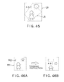
- the noise erasing is executed on the image data. More particularly, when the noise erasing command is issued for a portion of the image data, the result is reflected on all the frames which use the particular image data. If the noise erasing command is issued for an image frame, the noise erasing is executed on the circumscribing rectangle L6 of the image frame L5 as shown in FIG.45. Noise erasing areas and erasers are limited to regular rectangle in shape. If the position from the page origin of the objective image is changed, after the noise erasing area or an eraser is produced, relative positions of the image, the noise erasing area and the eraser are changed. The image frame may be moved, trimmed, joined, enlarged/reduced, or modified.
- FIGs.46A and 46B show an example of trimming. Even if the image frame in which the noise erasing area or the eraser was produced is deleted, the noise erasing area will remain. However, if the frame in which the objective image is arranged does not exist in the page, all the noise erasing areas and erasers within the page having the target image are automatically deleted. In FIGs.46A and 46B, the symbol M1 denotes an image frame, and M2 an eraser frame. Because of the restrictions of the system, it is impossible to store the image data for display which have been erased of noises. Therefore, image data for display are produced each time at the start of editing.
- the time allotted for the start of editing of the text for which the noise erasing is designated is relatively long.
- image arrangement sheet is roughly erasing of noises and then the level is changed for erasing noises from detailed portions by way of noise erasing area and erasers.
- the noise erasing processing is preferably conducted immediately after image arrangement, followed by various editing works.
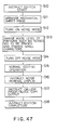
- the flow chart in FIG.47 shows the sequence of the noise erasing (Steps S10 to S18).
- This invention system is advantageous in that it can change noise conditions locally as the system scans all the regions first to detect all the black pixel of small to large sizes, and then takes out particular groups of black pixels which meet given conditions. It is suitable for printing as it can designate not only a pixel but the size and shape thereof. Since the system forms asymptotes based on the number of pixels and the flattening, forms hyperbolas based on a specified curvature and discriminates noises by judging whether the pixels are inside or outside the hyperbolas, it can effectively erase noises of various types.
Claims (6)
- Verfahren zur Rauscherfassung und Rauschunterdrückung bei Bilddaten, die durch eine Eingangseinrichtung gelesen und digitalisiert worden sind, das die folgenden Schritte umfaßt:beurteilt nach einer ausgewählten zweiten Bedingung, Rauschen sind, wobei die genannte zweite Bedingung Hyperbeln einer gegebenen Krümmung in einem Koordinatensystem umfaßt, mit der Anzahl der Pixel des geschlossenen Bereiches, der einer aufgelisteten Kontur entspricht, und dem Abflachungsverhältnis, das das Verhältnis der Länge zu der Breite des genannten geschlossenen Bereiches darstellt, als orthogonale Achsen, wobei die genannten Hyperbeln gegebene Asymptoten aufweisen, und diejenigen Merkmale des Onginalbildes als Rauschen beurteilt werden, deren entsprechender geschlossener Bereich eine Anzahl Pixel und ein Abflachungsverhältnis zeigt, die zu einem Punkt führen, der sich zwischen der genannten Hyperbel und den genannten orthogonalen Achsen befindet, wenn er im gleichen Koordinatensystem dargestellt wird.a) Bilden eines Konturbildes der gleichen Größe wie das Originalbild,b) Abtasten des genannten Konturbildes,c) nach Erfassung eines schwarzen Pixels in dem Konturbild verfolgen der Kontur, zu der das genannte schwarze Pixel gehört, wobei von den Koordinaten des genannten schwarzen Pixels ausgegangen wird,d) während des genannten Verfolgungsschritts speichem der Pixel der genannten Kontur in einem Speicher und Löschen der genannten Kontur in dem genannten Konturbild,e) nach Vollendung des Verfolgungsvorgangs fortsetzen des Abtastvorgangs,f) Auflisten aller Konturen die eine vorbestimmte erste Bedingung erfüllen, so daß eine grobe Unterscheidung zwischen Rauschmerkmalen und anderen Merkmalen ausgeführt wird,g) Wiederholen der Schritte c bis f, bis der Abtastvorgang des Konturbildes abgeschlossen ist,h) Löschen derjenigen Merkmale in dem Originalbild, die den Konturen entsprechen, die während des Schritts f) aufgelistet worden sind und die des weiteren,
- Verfahren zur Rauscherfassung und Rauschunterdrückung, wie in Anspruch 1 beansprucht, daß es des weiteren umfaßt, diejenigen Merkmale zur visuellen Bestätigung in Farbe anzuzeigen, die im Schritt h) als Rauschen beurteilt worden sind, wobei die genannten Asymptoten geändert werden können.
- Verfahren zur Rauscherfassung und Rauschunterdrückung, wie in einem der Ansprüche 1 und 2 beansprucht, wobei der Schritt a) das Kopieren eines Bildpixelmusters eines physikalischen Blattes in einen Speicher als einen Originalbereich umfaßt, ein Konturbereich mit derselben Größe wie der Originalbereich definiert wird, der Originalbereich in den Konturbereich kopiert wird und ein Konturpixelmuster des Originalbereichs in dem Konturbereich hergestellt wird,der Schritt b) umfaßt, das genannte Konturpixelmuster in dem Konturbereich von der oberen, linken Ecke zu der unteren, rechten Ecke abzutasten,der Schritt c) die Untersuchung der Konturlänge und das Fortsetzen der Verfolgung umfaßt, bis die Koordinaten des schwarzen Pixels, das als das Startpixel des Verfolgungsschritts dient, wieder erreicht werden,im Schritt f) diejenigen Konturen aufgelistet werden, deren Konturlängen kürzer als eine vorbestimmte Länge sind,der Schritt h) die Umwandlung der während des Schritts f) hergestellten Liste in eine Rauschlistendatei und das Unterdrücken jener Daten aus den Rauschlistendateien umfaßt, wobei die Merkmale, zu denen sie gehören, als Rauschen beurteilt werden, und jene Merkmale in dem Originalbereich gelöscht werden,wobei das Verfahren des weiteren umfaßt, die Daten des Originalbereiches nach dem genannten Löschungsvorgang auf eine Platte zu schreiben, so daß gespeicherte Bilddaten entsprechend den Bildem ohne Rauschen gebildet werden.
- Verfahren zur Rauscherfassung und Rauschunterdrückung, wie in Anspruch 3 beansprucht, wobeider Schritt c) es umfaßt, 8 benachbarte Pixel um das genannte erfaßte schwarze Pixel herum in dem Konturbereich zu nehmen, undder Schritt d) es umfaßt, den verfolgten, verwendeten Koordinatenwert und die Daten der 8 benachbarten Pixel in dem Speicher zu speichem, sowie den Austausch der schwarzen Pixel der erhaltenen Daten der 8 benachbarten Pixel durch weiße Pixel.
- Verfahren zur Rauscherfassung und Rauschunterdrückung, wie in Anspruch 3 beansprucht, wobei die genannte Umwandlung in Rauschlistendateien es umfaßt, die während des Schritts f) aufgelisteten Daten in Koordinatendaten umzuwandeln, die umgewandelten Daten der Rauschliste hinzuzufügen, die Koordinatenachse und die Daten der 8 benachbarten Pixel in Rauschblockinformationen umzuwandeln und die Rauschblockinformationen in der Rauschliste zu speichem.
- Verfahren zur Rauscherfassung und Rauschunterdrückung, wie in Anspruch 5 beansprucht, wobei die genannten Rauschblockinformationen die oberen linken Koordinaten minx und miny und die unteren, rechten Koordinaten maxx und maxy eines Rechtecks, das ein Rauschen umgibt, die Gesamtanzahl der Pixel, die Umfangslänge, die Abflachung einer geschlossenen Bereichsform und die Koordinaten von minx und maxx jeder Linie sind.
Applications Claiming Priority (2)
| Application Number | Priority Date | Filing Date | Title |
|---|---|---|---|
| JP268341/91 | 1991-09-19 | ||
| JP3268341A JP2958584B2 (ja) | 1991-09-19 | 1991-09-19 | ノイズ除去方法 |
Publications (3)
| Publication Number | Publication Date |
|---|---|
| EP0533177A2 EP0533177A2 (de) | 1993-03-24 |
| EP0533177A3 EP0533177A3 (en) | 1994-12-14 |
| EP0533177B1 true EP0533177B1 (de) | 1999-04-07 |
Family
ID=17457200
Family Applications (1)
| Application Number | Title | Priority Date | Filing Date |
|---|---|---|---|
| EP92115956A Expired - Lifetime EP0533177B1 (de) | 1991-09-19 | 1992-09-17 | Verfahren zur Rauschdetektion und Rauschunterdrückung |
Country Status (4)
| Country | Link |
|---|---|
| US (1) | US5355421A (de) |
| EP (1) | EP0533177B1 (de) |
| JP (1) | JP2958584B2 (de) |
| DE (1) | DE69228848T2 (de) |
Cited By (1)
| Publication number | Priority date | Publication date | Assignee | Title |
|---|---|---|---|---|
| US8271470B2 (en) * | 2007-06-09 | 2012-09-18 | Apple Inc. | Auto-activation of fonts |
Families Citing this family (15)
| Publication number | Priority date | Publication date | Assignee | Title |
|---|---|---|---|---|
| US5491812A (en) * | 1992-09-28 | 1996-02-13 | Conner Peripherals, Inc. | System and method for ethernet to SCSI conversion |
| JP2904671B2 (ja) * | 1993-03-03 | 1999-06-14 | 大日本スクリーン製造株式会社 | 多階調画像の修正装置 |
| JP3096388B2 (ja) * | 1994-06-22 | 2000-10-10 | シャープ株式会社 | 電子複写機における自動画質調整装置 |
| US5600772A (en) * | 1994-08-17 | 1997-02-04 | Printronix, Inc. | Bit map character convertor using chain-codes for the character filling process |
| US5764812A (en) * | 1995-11-10 | 1998-06-09 | Ricoh Company, Ltd. | Image processing apparatus for providing an isolated-dot removing function |
| KR100615839B1 (ko) * | 1998-10-26 | 2006-08-25 | 소니 가부시끼 가이샤 | 화상 처리 장치, 화상 처리 방법, 학습 장치 및 학습 방법 |
| JP3846133B2 (ja) * | 1999-11-17 | 2006-11-15 | セイコーエプソン株式会社 | 画像処理装置および印刷装置 |
| US6650790B1 (en) * | 2000-06-09 | 2003-11-18 | Nothshore Laboratories, Inc. | Digital processing apparatus for variable image-size enlargement with high-frequency bandwidth synthesis |
| US6927780B2 (en) * | 2002-01-14 | 2005-08-09 | Seiko Epson Corporation | Fast text/graphics resolution improvement with chain-code table look-up |
| US20040021769A1 (en) * | 2002-07-31 | 2004-02-05 | Eastman Kodak Company | Method for detecting artifacts for use in a film scanner |
| WO2005109849A1 (en) * | 2004-05-05 | 2005-11-17 | Kodak Polychrome Graphics, Llc | Halftone proofing with inkjet printers |
| WO2007029235A2 (en) * | 2005-09-05 | 2007-03-15 | Algosoft Limited | Automatic digital film and video restoration |
| JP2007192752A (ja) * | 2006-01-20 | 2007-08-02 | Horon:Kk | エッジ検出方法およびエッジ検出装置 |
| JP4315458B2 (ja) | 2006-03-31 | 2009-08-19 | キヤノン株式会社 | インクジェット記録装置、画像処理装置および画像処理方法 |
| US8184917B2 (en) * | 2009-08-05 | 2012-05-22 | Brother Kogyo Kabushiki Kaisha | Image processor |
Family Cites Families (13)
| Publication number | Priority date | Publication date | Assignee | Title |
|---|---|---|---|---|
| US3700797A (en) * | 1969-12-31 | 1972-10-24 | Electronic Image Systems Corp | Facsimile noise deletion and coding system |
| JPS4934385A (de) * | 1972-07-28 | 1974-03-29 | ||
| JPS538495B2 (de) * | 1974-05-14 | 1978-03-29 | ||
| JPS6011966A (ja) * | 1983-07-01 | 1985-01-22 | Toshiba Corp | 画像処理装置 |
| IL70213A (en) * | 1983-11-13 | 1988-02-29 | Paul Fenster | Digital fluorographic image enhancement system |
| JPS6140684A (ja) * | 1984-07-31 | 1986-02-26 | Omron Tateisi Electronics Co | 輪郭追跡装置 |
| US4769849A (en) * | 1985-12-19 | 1988-09-06 | The Palantir Corporation | Method and apparatus for separating overlapping patterns |
| JPH029389A (ja) * | 1987-05-25 | 1990-01-12 | Teijin Ltd | 新規生理活性ポリペプチド |
| JPH02260078A (ja) * | 1989-03-31 | 1990-10-22 | Ricoh Co Ltd | 画像のノイズ自動除去装置 |
| US5029226A (en) * | 1989-10-10 | 1991-07-02 | Unisys Corporation | Method and apparatus for effecting spot/void filtering of image data |
| US5048096A (en) * | 1989-12-01 | 1991-09-10 | Eastman Kodak Company | Bi-tonal image non-text matter removal with run length and connected component analysis |
| JPH0425980A (ja) * | 1990-05-22 | 1992-01-29 | Fuji Photo Film Co Ltd | ノイズ除去方法 |
| US5189710A (en) * | 1990-09-17 | 1993-02-23 | Teknekron Communications Systems, Inc. | Method and an apparatus for generating a video binary signal for a video image having a matrix of pixels |
-
1991
- 1991-09-19 JP JP3268341A patent/JP2958584B2/ja not_active Expired - Fee Related
-
1992
- 1992-09-15 US US07/944,940 patent/US5355421A/en not_active Expired - Fee Related
- 1992-09-17 EP EP92115956A patent/EP0533177B1/de not_active Expired - Lifetime
- 1992-09-17 DE DE69228848T patent/DE69228848T2/de not_active Expired - Fee Related
Cited By (1)
| Publication number | Priority date | Publication date | Assignee | Title |
|---|---|---|---|---|
| US8271470B2 (en) * | 2007-06-09 | 2012-09-18 | Apple Inc. | Auto-activation of fonts |
Also Published As
| Publication number | Publication date |
|---|---|
| EP0533177A2 (de) | 1993-03-24 |
| US5355421A (en) | 1994-10-11 |
| DE69228848T2 (de) | 1999-08-05 |
| JP2958584B2 (ja) | 1999-10-06 |
| EP0533177A3 (en) | 1994-12-14 |
| DE69228848D1 (de) | 1999-05-12 |
| JPH0581424A (ja) | 1993-04-02 |
Similar Documents
| Publication | Publication Date | Title |
|---|---|---|
| EP0533177B1 (de) | Verfahren zur Rauschdetektion und Rauschunterdrückung | |
| US6072941A (en) | Image processing apparatus and method which classifies images according to attributes | |
| US5086497A (en) | Image output command method for image processing system | |
| US5528732A (en) | Reprographic device for making copies with multi-spaced lines | |
| EP0320014B1 (de) | Bildverarbeitungssystem | |
| EP0249948B1 (de) | Bildinformationsverarbeitungsgerät | |
| US5163122A (en) | Image processing system | |
| US5642473A (en) | Paper saving reprographic device | |
| JP2000200350A (ja) | 情報処理方法及び装置 | |
| US5592574A (en) | Method and apparatus for expansion of white space in document images on a digital scanning device | |
| US5195174A (en) | Image data processing apparatus capable of composing one image from a plurality of images | |
| US5278950A (en) | Image composing method | |
| JPH032979A (ja) | 画像修正方法及び装置 | |
| JPH03105687A (ja) | 画像合成方法 | |
| US5218460A (en) | Method for pattern selection involving scaling-up circumscribed rectangles | |
| JPH05292294A (ja) | デジタル複写機 | |
| US5583955A (en) | Image processing apparatus | |
| JP3064305B2 (ja) | ディジタル複写機 | |
| JP2957050B2 (ja) | 画像データ拡大装置 | |
| JPH0581397A (ja) | ページスクロール方法及び画像処理装置 | |
| EP0418868A2 (de) | Bildverarbeitungssystem | |
| JPH0581428A (ja) | 画像処理方法 | |
| JPH0713541A (ja) | 画像処理方法及び装置 | |
| JPH05266154A (ja) | 画像処理方法 | |
| JP2866464B2 (ja) | 線図形境界抽出方法 |
Legal Events
| Date | Code | Title | Description |
|---|---|---|---|
| PUAI | Public reference made under article 153(3) epc to a published international application that has entered the european phase |
Free format text: ORIGINAL CODE: 0009012 |
|
| AK | Designated contracting states |
Kind code of ref document: A2 Designated state(s): DE FR GB |
|
| PUAL | Search report despatched |
Free format text: ORIGINAL CODE: 0009013 |
|
| AK | Designated contracting states |
Kind code of ref document: A3 Designated state(s): DE FR GB |
|
| 17P | Request for examination filed |
Effective date: 19950529 |
|
| 17Q | First examination report despatched |
Effective date: 19970612 |
|
| GRAG | Despatch of communication of intention to grant |
Free format text: ORIGINAL CODE: EPIDOS AGRA |
|
| GRAG | Despatch of communication of intention to grant |
Free format text: ORIGINAL CODE: EPIDOS AGRA |
|
| GRAH | Despatch of communication of intention to grant a patent |
Free format text: ORIGINAL CODE: EPIDOS IGRA |
|
| GRAH | Despatch of communication of intention to grant a patent |
Free format text: ORIGINAL CODE: EPIDOS IGRA |
|
| GRAA | (expected) grant |
Free format text: ORIGINAL CODE: 0009210 |
|
| AK | Designated contracting states |
Kind code of ref document: B1 Designated state(s): DE FR GB |
|
| REF | Corresponds to: |
Ref document number: 69228848 Country of ref document: DE Date of ref document: 19990512 |
|
| ET | Fr: translation filed | ||
| PLBE | No opposition filed within time limit |
Free format text: ORIGINAL CODE: 0009261 |
|
| STAA | Information on the status of an ep patent application or granted ep patent |
Free format text: STATUS: NO OPPOSITION FILED WITHIN TIME LIMIT |
|
| 26N | No opposition filed | ||
| REG | Reference to a national code |
Ref country code: GB Ref legal event code: IF02 |
|
| PGFP | Annual fee paid to national office [announced via postgrant information from national office to epo] |
Ref country code: GB Payment date: 20040827 Year of fee payment: 13 Ref country code: FR Payment date: 20040827 Year of fee payment: 13 |
|
| PGFP | Annual fee paid to national office [announced via postgrant information from national office to epo] |
Ref country code: DE Payment date: 20041027 Year of fee payment: 13 |
|
| PG25 | Lapsed in a contracting state [announced via postgrant information from national office to epo] |
Ref country code: GB Free format text: LAPSE BECAUSE OF NON-PAYMENT OF DUE FEES Effective date: 20050917 |
|
| PG25 | Lapsed in a contracting state [announced via postgrant information from national office to epo] |
Ref country code: DE Free format text: LAPSE BECAUSE OF NON-PAYMENT OF DUE FEES Effective date: 20060401 |
|
| GBPC | Gb: european patent ceased through non-payment of renewal fee |
Effective date: 20050917 |
|
| PG25 | Lapsed in a contracting state [announced via postgrant information from national office to epo] |
Ref country code: FR Free format text: LAPSE BECAUSE OF NON-PAYMENT OF DUE FEES Effective date: 20060531 |
|
| REG | Reference to a national code |
Ref country code: FR Ref legal event code: ST Effective date: 20060531 |
|
| REG | Reference to a national code |
Ref country code: GB Ref legal event code: 732E |