EP0530725B1 - Austentischer rostfreier Stahl mit hohe Beständigkeit gegen durch Strahlung verursachte Entmischung - Google Patents
Austentischer rostfreier Stahl mit hohe Beständigkeit gegen durch Strahlung verursachte Entmischung Download PDFInfo
- Publication number
- EP0530725B1 EP0530725B1 EP92114846A EP92114846A EP0530725B1 EP 0530725 B1 EP0530725 B1 EP 0530725B1 EP 92114846 A EP92114846 A EP 92114846A EP 92114846 A EP92114846 A EP 92114846A EP 0530725 B1 EP0530725 B1 EP 0530725B1
- Authority
- EP
- European Patent Office
- Prior art keywords
- irradiation
- stainless steel
- austenitic stainless
- reactor
- steel
- Prior art date
- Legal status (The legal status is an assumption and is not a legal conclusion. Google has not performed a legal analysis and makes no representation as to the accuracy of the status listed.)
- Expired - Lifetime
Links
Images




Classifications
-
- C—CHEMISTRY; METALLURGY
- C22—METALLURGY; FERROUS OR NON-FERROUS ALLOYS; TREATMENT OF ALLOYS OR NON-FERROUS METALS
- C22C—ALLOYS
- C22C38/00—Ferrous alloys, e.g. steel alloys
- C22C38/18—Ferrous alloys, e.g. steel alloys containing chromium
- C22C38/20—Ferrous alloys, e.g. steel alloys containing chromium with copper
-
- C—CHEMISTRY; METALLURGY
- C22—METALLURGY; FERROUS OR NON-FERROUS ALLOYS; TREATMENT OF ALLOYS OR NON-FERROUS METALS
- C22C—ALLOYS
- C22C38/00—Ferrous alloys, e.g. steel alloys
- C22C38/18—Ferrous alloys, e.g. steel alloys containing chromium
- C22C38/40—Ferrous alloys, e.g. steel alloys containing chromium with nickel
- C22C38/50—Ferrous alloys, e.g. steel alloys containing chromium with nickel with titanium or zirconium
-
- C—CHEMISTRY; METALLURGY
- C22—METALLURGY; FERROUS OR NON-FERROUS ALLOYS; TREATMENT OF ALLOYS OR NON-FERROUS METALS
- C22C—ALLOYS
- C22C38/00—Ferrous alloys, e.g. steel alloys
- C22C38/18—Ferrous alloys, e.g. steel alloys containing chromium
- C22C38/40—Ferrous alloys, e.g. steel alloys containing chromium with nickel
- C22C38/46—Ferrous alloys, e.g. steel alloys containing chromium with nickel with vanadium
-
- C—CHEMISTRY; METALLURGY
- C22—METALLURGY; FERROUS OR NON-FERROUS ALLOYS; TREATMENT OF ALLOYS OR NON-FERROUS METALS
- C22C—ALLOYS
- C22C38/00—Ferrous alloys, e.g. steel alloys
- C22C38/18—Ferrous alloys, e.g. steel alloys containing chromium
- C22C38/40—Ferrous alloys, e.g. steel alloys containing chromium with nickel
- C22C38/48—Ferrous alloys, e.g. steel alloys containing chromium with nickel with niobium or tantalum
-
- Y—GENERAL TAGGING OF NEW TECHNOLOGICAL DEVELOPMENTS; GENERAL TAGGING OF CROSS-SECTIONAL TECHNOLOGIES SPANNING OVER SEVERAL SECTIONS OF THE IPC; TECHNICAL SUBJECTS COVERED BY FORMER USPC CROSS-REFERENCE ART COLLECTIONS [XRACs] AND DIGESTS
- Y02—TECHNOLOGIES OR APPLICATIONS FOR MITIGATION OR ADAPTATION AGAINST CLIMATE CHANGE
- Y02E—REDUCTION OF GREENHOUSE GAS [GHG] EMISSIONS, RELATED TO ENERGY GENERATION, TRANSMISSION OR DISTRIBUTION
- Y02E30/00—Energy generation of nuclear origin
- Y02E30/10—Nuclear fusion reactors
-
- Y—GENERAL TAGGING OF NEW TECHNOLOGICAL DEVELOPMENTS; GENERAL TAGGING OF CROSS-SECTIONAL TECHNOLOGIES SPANNING OVER SEVERAL SECTIONS OF THE IPC; TECHNICAL SUBJECTS COVERED BY FORMER USPC CROSS-REFERENCE ART COLLECTIONS [XRACs] AND DIGESTS
- Y10—TECHNICAL SUBJECTS COVERED BY FORMER USPC
- Y10S—TECHNICAL SUBJECTS COVERED BY FORMER USPC CROSS-REFERENCE ART COLLECTIONS [XRACs] AND DIGESTS
- Y10S376/00—Induced nuclear reactions: processes, systems, and elements
- Y10S376/90—Particular material or material shapes for fission reactors
Definitions
- This invention relates to austenitic stainless steel for use as a material for constituting a reactor such as a light water reactor, a fast breeder reactor and a nuclear fusion reactor, and more particularly to austenitic stainless steel having a superior irradiation-induced segregation resistance best suited for preventing the concentration change of the constituents in the crystal grain boundary (that is, for preventing irradiation-induced segregation) when the steel is exposed to a neutron-irradiating environment.
- austenitic stainless steel SUS304 or SUS316 has been used as equipment parts of a reactor core of a light water reactor.
- the equipment parts of the reactor core is subjected to neutron irradiation, and therefore it is desired to use a material of a superior irradiation resistance for the equipment parts.
- the most important properties with respect to the irradiation resistance of the material are irradiation embrittlement and stress corrosion cracking.
- EP-A-0 067 501 corresponding to JP-A-57 155 352 discloses, for example, a Cr-Ni austenite stainless steel containing preferably 0.003 - 0.01 % C and nitrogen in an amount exceeding the impurity level, preferably 0.05 - 0.15 %, wherein due to the additon of nitrogen austenite stainless steel exhibits higher radiation resistance.
- Said steel may further contain up to 1 % Si, up to 2 % Mn and 2 - 3 % Mo. It has been pointed out, for example, in Japanese Patent Unexamined Publication No. 57-155352 that the irradiation embrittlement can be improved by adding a trace amount of an additional element to the material. It is described in Japanese Patent Unexamined Publication No. 62-93075 that the stress corrosion cracking under irradiation can also be improved by adding a trace amount of an element.
- an austenitic stainless steel of the present invention having a superior resistance to irradiation-induced segregation, consisting, by weight, of : 0.001 to 0.008% C, not more than 1% Si; not more than 2% Mn; 15 to 22% Cr; 8 to 15% Ni; at least one kind additive selected from the group consisting of Ti more than 0.2%, but not more than 0.6%, Zr more than 0.2%, but not more than 1.14%, Hf more than 0.2%, but not more than 2.24%, V more than 0.2%, but not more than 0.64%, Nb more than 0.5%, but not more than 1.17%, and Ta more than 0.5%, but not more than 2.27%; optionally 0,001 to 0,1% N, optionally 0 to 3% Mo, and the balance Fe and incidental impurities, said at least one kind additive being in a solid solution state, said steel having a wholly austenitic structure substantially free of carbide.
- the concentration change of the constituents of the austenitic stainless steel in the crystal grain boundary which is induced under irradiation, is attributable to the movement of irradiation point defects (that is, vacancies) introduced into the material by the irradiation, and also to the movement of interstitial atoms to the grain boundary.
- the constituent element Cr is moved away from the grain boundary by an exchange mechanism which effects a mutual action with the vacancies to move in a direction opposite to the direction of flow of the vacancies.
- the constituent element Ni is moved to the grain boundary by a mechanism which effects a mutual action with the interstitial atoms to be dragged by the atoms between the lattices, so that the concentration is increased in the grain boundary.
- Si, as well as P and S which are among the incidental impurity elements are moved by the latter mechanism to be dragged, so that the concentrations thereof are increased in the grain boundary.
- the decreasing of the amount of the point defects which serve as the drive force for the constituent elements Cr, Ni, Si, P and S has been found as a method of preventing the concentration change of the constituent elements in the grain boundary.
- a method of decreasing the amount of the point defects occurring by the irradiation there has been invented a method of adding the element which effects a strong mutual action with the vacancies to trap the vacancies in this element, thereby promoting a mutual extinction of the vacancies and the interstitial atoms, and the additions of various kinds of elements as well as the effective addition amounts have been studied.
- the addition amount exceeds the upper limit value, the weldability and the workability are adversely affected, and besides the austenitic structure becomes unstable to produce a ferrite phase or a martensitic phase in the grain boundary and etc., which may induce cracking in the nuclear reactor. Therefore, these elements in the above addition range are solid-solutioned in the austenitic stainless steel.
- Ti is 0.45 to 0.6%
- Zr is 0.3 to 1.0%
- Hf is 0.7 to 1.9%
- V is 0.3 to 0.55%
- Nb is 0.5 to 0.9%
- Ta is 1 to 2.
- the other constituent elements are in the following weight range.
- Si makes the deoxidation perfect when melting the steel, and therefore Si can be added in the range of not more than 1%.
- This element is also effective in enhancing the resistance to the irradiation embrittlement; however, if this content exceeds 1%, the stress corrosion cracking property in high temperature water is adversely affected, and therefore its content is not more than 1%. Preferable range thereof is not more than 0.5%.
- the steel can be used as a material for part of the above equipment.
- this element in order to further increase the strength and the workability, it is preferred to add this element.
- this content exceeds 2%, this invites embrittlement, and preferably its content is 1.0 to 1.8 in order to achieve a good workability.
- the Cr content is less than 15%, the corrosion resistance and the strength are lowered, and if this content exceeds 22%, the irradiation resistance is lowered. Further, during the irradiation, this element produces the a phase which is harmful to mechanical properties, and therefore preferably its content is 15 to 18%. In order to suppress the occurrence of the ⁇ phase due to a fluctuation of the composition of the material as much as possible, 17 to 20% is preferred.
- the N content is preferably 8 to 15%.
- the amount of C which is the austenitic phase-stabilizing element must be limited to a low value for the above-mentioned reason, 10 to 14% is preferred for the stabilization of the austenitic phase.
- the steel can be used as a material for part of the above equipment.
- this is an effective addition element.
- the amount of addition exceeds 3%, it promotes the precipitation of the ⁇ phase, which invites the embrittlement of the material, and therefore this is not desirable.
- Table 1 shows chemical compositions (wt.%) (except for a main component, Fe) of steel kind Nos. 2, 3, 4, 5, 6 and 7 of austenitic stainless steel of the present invention having a superior resistance to irradiation-induced segregation, as well as a chemical composition of steel kind No. 1 of comparative steel, in which steels of the Example 1 of the present invention both carbon and silicon were contained as impurities, and several % ferrite occurred at the stage of an ingot, however, wholly austenitic uniform structure was able to be produced by effecting solution heat treatment after hot rolling.
- No. 1 corresponds to SUS316L steel.
- the steels of Nos. 2, 3, 4, 5, 6 and 7 contained Ti, Zr, Hf, V, Nb and Ta, respectively, in the addition range of the present invention.
- the Si content of each steel is as small as 0.01%, and this element is incidentally contained.
- Each of these steels was prepared by melting under vacuum, and casting the molten metals into an ingot of 10 kg, and hot rolling the ingot at 1050°C, and then cold rolling it, and finally subjecting it to a solution treatment for 15 to 30 minutes.
- Samples cut from these steels by electropolishing were subjected to an irradiation test in which an electron irradiation simulating a neutron irradiation was applied to the samples in a ultra-high voltage electronic microscope.
- the electron acceleration voltage was 1 MV
- the irradiation amount was 10 dpa (1 dpa is equivalent to about 1 ⁇ 10 21 n/cm 2 of a neutron irradiation amount.
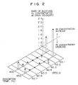
- Figs. 1 and 2 respectively show the rate of decrease of the Cr concentration and the rate of increase of the Ni concentration for each steel at irradiation temperatures of 400°C and 450°C, these concentration decrease and increase being induced in the grain boundary by the irradiation.
- the concentration analysis was effected by an EDX analysis.
- the irradiation-induced segregation at either temperature was extremely suppressed in any of the steels of the present invention, as compared with the comparative steel No. 1.
- the rates of change of the Cr and Ni concentrations in the grain boundary are values allocated by the concentrations in the grain boundary after the irradiation.
- Table 2 shows chemical compositions (except for a main component, Fe) of austenitic stainless steel Nos. 8, 9, 10 and 13 of the present invention, as well as chemical compositions of comparative steel Nos. 11 and 12, in which steels both carbon and silicon were contained as incidental impurities, and wholly austenitic uniform structure was able to be obtained by effecting a solution heat treatment after hot rolling.
- 11 and 12 respectively contain Nb and Ta in a small amount, and are subjected to the irradiation-induced segregation (the decrease of the Cr concentration and the increase of the Ni concentration in the grain boundary) of a level more than that of the comparative steel No. 1 (SUS316L) with no addition element. It will be appreciated that the irradiation-induced segregation of either of Cr and Ni is extremely suppressed in the steel Nos. 2, 8, 9, 10 and 13 of the present invention.
- the movement to the grain boundary is caused by the irradiation, and it is thought that this occurs because the movement of the point defects (that is, the vacancies) introduced into the material by the irradiation, as well as the movement of the interstitial atoms to the grain boundary, is vigorous.
- the fact that the movement to the grain boundary does not occur in the steel Nos. 2, 8, 9, 10 and 13 of the present invention indicates the mutual extinction between the vacancies and the interstitial atoms is promoted by the addition element to suppress the moving of these point defects to the grain boundary. This is one phenomenon which clearly shows the effect of the present invention.
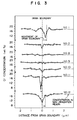
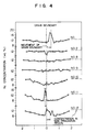
- Fig. 5 shows the results of X-ray diffraction of steels, prepared by adding Ti, Zr, Hf, V, Nb and Ta according to the same process as in Example 1, using the comparative steel No. 1 (SUS316L) of Example 1 as a base alloy, the X-ray diffraction being carried out to determine how much the extent of each of these elements was able to be solid-solutioned.
- Each of steel Nos. 14 to 19 contains a respective one of the above elements, and the amount of each additive added to the steel No. 1 was, by weight, 0.45% Ti, 0.86% Zr, 1.7% Hf, 0.48% V, 0.87% Nb, and 1.71% Ta.
- each of the steels respectively having these elements added thereto only the peak of the austenitic structure was able to be observed as in the comparative steel No. 1 (SUS316L), and it can be appreciated that all of the elements can be solid-solutioned in this range and that each of the steels has a wholly austenitic structure substantially free of carbide.
- These steels having the addition elements are steels of the present invention. However, if the amount of addition of each element exceeds the above value, a peak of the ferrite phase appears in each steel. Therefore, in view of the embrittlement and etc., preferably, the maximum addition amounts should be as in the steels shown in Fig. 5.
- a tensile test was carried out.
- the overall length was 50 mm
- the length of a parallel portion was 20 mm
- the cross-sectional shape of the parallel portion was 2 ⁇ 2 (cm)
- the radius of the ends of the parallel portion wa R4.
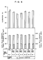
- Fig. 6 shows the results of the tensile strength and the yield strength of 0.2% obtained by the tensile test in which two test pieces for each steel were subjected to the tensile test at room temperature.
- the 0.2% yield strength is represented by the height of a hatched bar, and the tensile strength is represented by the height of the hatched portion plus the height of a void portion just above the hatched portion.
- the values of the 0.2% yield strength and tensile strength which are not less than those obtained with the comparative steel No. 1 can be obtained with the steels of the present invention.
- the Zr-added steel No. 2 is about 20% smaller, good results sufficiently exceeding the standards of the design of the equipment within the nuclear reactor and etc., were obtained when any of the elements was added, and it will be appreciated that the mechanical properties of the steels of the present invention are suited as the structural material.
- Each of the steel Nos. 2, 8, 9, 10, 5 and 6 of the present invention as described in Example 4 was cut into a piece of a rectangular shape (20 ⁇ 1 ⁇ 1 mm), and nitrogen was added to these pieces at 1050° in an atmosphere of a methane-hydrogen mixture gas in an induction furnace to prepare steels having the nitrogen content of about 0.01 wt.%, about 0.10 wt.% and about 0.21 wt.%. These steels were subjected to a homogeneous solid-solutioning treatment in argon at 1150°C for 30 minutes, and then a sample for the observation by an electronic microscope was cut from each of the steels, and was subjected to electron irradiation (500°C) as in Example 1.
- the N content should not exceed 0.1%. Also, if the amount of the irradiation exceeds 3 dpa with respect to the 0.10% N-added material, similar results are obtained, and therefore it is not preferred to use such a material as a member subjected to a high dose of irradiation.
- the irradiation amount is not more than 3 dpa, the irradiation-induced segregation is suppressed. Even the irradiation amount of 10 dpa does not pose any problem in a case of the 0.01% N-added material, and results similar to those in Example 1 (Figs. 1 and 2) were obtained.
- Example 4 Each of the steel Nos. 2, 8, 9, 10, 5 and 6 of the present invention as described in Example 4 was cut into a piece of a rectangular shape (20 ⁇ 1 ⁇ 1 mm), and carbon (C) was added to these pieces at 1050° in an atmosphere of a ammonia-hydrogen mixture gas in an induction furnace to prepare steels having the carbon content of about 0.03 wt.% and about 0.06 wt.%. These steels were subjected to a homogeneous solid-solutioning treatment in argon at 1150°C for 30 minutes, and then a sample for the observation by an electronic microscope was cut from each of the steels, and was subjected to electron irradiation (500°C) as in Example 1.
- C ammonia-hydrogen mixture gas
- Fig. 7 is a partly-broken, schematic, perspective view of an important portion of a reactor core portion of a boiling light water reactor (BWR).
- reference numeral 1 denotes a neutron source pipe
- reference numeral 2 a reactor core support plate
- reference numeral 3 a neutron instrumentation pipe
- reference numeral 4 a control rod
- reference numeral 5 a shroud
- reference numeral 6 an upper lattice plate.
- the concentration change of the constituent elements in the grain boundary under the neutron irradiation can be suppressed, and the corrosion resistance under irradiation, the irradiation-induced SCC and the embrittlement in the grain boundary can be prevented.
- the steel of the present invention can be used for parts, provided between these structural members and equipment, other than those shown in Fig. 7, and by doing so, similar effects can be obtained. Further, by using the steel of the present invention for structural members and equipment of a reactor core portion of other water-cooled reactor than the boiling water reactor, similar effects can be expected.
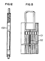
- the neutron instrumentation pipe 3 When the steels of the present invention in Examples 1 to 6 are used for the above-mentioned neutron source pipe 1, the neutron instrumentation pipe 3, a control rod insertion pipe, a casing of a crisscross shape in which this rod insertion pipe is inserted, a channel box 111 (Fig. 13) of a fuel assembly 7, and a fuel cladding pipe 102 (Figs. 12, 13) they are superior in neutron irradiation SCC resistance.
- a steel ingot is hot rolled, and a solution treatment is applied, and subsequently cold rolling and annealing are effected, these steps being repeated.
- Each of the reactor core support plate 2, the shroud 5 and the upper lattice plate 6 is obtained by hot rolling an ingot of the steel of the present invention and subjecting it to a solution treatment.
- the reactor core is constituted by the devices shown below, and the steels of the present invention can be also used for these structural members in the reactor.
- the structural members in the reactor include a upper mirror spray nozzle 8, a vent nozzle 9, a pressure vessel lid 10, a pressure vessel flange 11, a measurement nozzle 12, a steam separator 13, a shroud head 14, a feed water inlet nozzle 15, a jet pump 16, a re-circulating water outlet nozzle 17, a steam dryer 18, a steam seasoning device 18, a steam outlet nozzle 19, a feed water sparer 20, a core spray nozzle 21, a lower core lattice 22, a recirculating water inlet nozzle 23, a baffle plate 24, a control rod guide pipe 25, and so on.
- the steels of the present invention can also be applied to a new-type converter reactor (ABWR) having an internal pump in the reactor, and a pressurized water reactor (PWR).
- ABWR new-type converter reactor
- PWR pressurized water reactor
- the internal pump is provided in the reactor instead of the jet pump 16 of the above-mentioned BWR, and other portions are similar to those of the BWR. Therefore, the alloys of the present invention can be applied to the equipment and structural members within the ABWR reactor, as described above for the BWR. The use of the alloys of the present invention provides a higher safety.
- Fig. 8 is a longitudinal cross sectional schematic view of a torus-type nuclear fusion reactor.
- the fusion reactor comprises poloidal magnetic coils 34 and diver coils 38 both for effecting the heating and controlling of plasma 30, toroidal coils 36 for confining the plasma 30, a hollow vacuum vessel 33 of a doughnut shape disposed within the toloidal coils 36, a blanket 35 for feeding a coolant such as helium so as to effect heat exchange which blanket is disposed within the vacuum vessel and within which blanket plasma is generated with deuterium or tritium being introduced therein, a shielding tubular body 39 provided on the inside of the vacuum vessel, diverter plates 31 disposed at the inside of the shielding tubular body so that the diverter plate is connected to the diverter coil 38 and is supported by a cooling tube header onto which diverter plates a part of plasma (impurities of He etc.) taken out from the plasma 30 is applied, an exhaust pump 43 connected to an opening 39a of the shielding tubular body 39 through an exhausting tube 42, and
- These structural members and equipment are subjected to irradiation of various corpuscular rays leaking from a large amount of neutrons and plasmas, and also are designed to be in contact with water for cooling purposes, and therefore are brought into contact with hot water.
- the concentration change of the constituents in the grain boundary under irradiation can be prevented, and the corrosion resistance is enhanced.
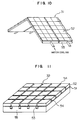
- Fig. 10 is a perspective view of a diverter, in which ceramic tiles 52 are bonded to a metal member 55 by brazing
- Fig. 11 is a perspective view of the first wall, in which the reference numeral 51 shows brazing, 52 the ceramic tiles, 53 grooves for receiving a brazing plate, and 54 shows grooves.
- the diverter 31, the first wall 32 and the vacuum vessel 33 are constituted by water-cooled structure made of the steel of the present invention.
- the diverter 31 and the first wall 32 has a construction in which a block of a low atomic number (for example, SiC, Si 3 N 4 , AlN, Al 2 O 3 , ceramic tiles 4) bonded mechanically or metallurgically to the surface of the metallic member of the cooled structure.
- the steels of the present invention can be used for these, and they are constituted by a plate or a pipe.
- the nuclear fusion apparatus comprises a toroidal coil and an evacuator in addition to a toroidal coil 34.
- Other types of nuclear fusion apparatus include an open magnetic field type, and an inertia-confined laser heating type, and the steels of the present invention can be applied to these types, and a high reliability can be obtained.
- Example 7 When the parts of the BWR in Example 7 were subjected to the neutron irradiation (not less than about 5 ⁇ 10 20 n/cm 2 ) in an environment of water at a high temperature of 288°C and a high pressure of 7 MPa, a stress corrosion cracking developed in these parts. When these parts were made of austenitic stainless steels SUS304, SUS316, SUS316L and so on, the stress corrosion cracking similarly occurred. However, when the similar neutron irradiation was applied to the above parts made of the steel Nos. 2, 8, 9, 10, 5 and 6 of the present invention in Example 4, any stress corrosion cracking did not occur even under the neutron irradiation of 1 ⁇ 10 22 n/cm 2 .
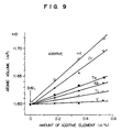
- Fig. 9 shows how the volume occupied by one atom in Steel No. 1, SUS316L steel, (that is, the atomic volume) changes with the amount of addition of the addition element, this result being found by X-ray diffraction as in Fig. 5.
- the atomic volume increases linearly with the increase of the addition amount, and therefore it will be appreciated that all of these elements are an oversize element greater than the average atomic size of Steel No. 1 (SUS316L steel). From this result, it has been found that the force of the mutual action between the vacancies and these elements is attributable to the elastic strain field which expands the crystal lattice produced in SUS316L steel by these elements.
- the order of the sizes was Hf > Zr > Nb > Ti > V > Ta. Therefore, the forces of the mutual action between these elements and the vacancies is higher in this order, and as a result the amount of the mutual extinction of the point defects is larger in this order.
- the amount of formation of the secondary defects (the transition loop, the atom hole assembly, voids etc.) in the crystal grain decreases with the increase of the size factor of the addition element, and therefore the amount of the point defects, consumed for the formation of the secondary defects and extinguished, decreases with the increase of the size factor.
- the minimum addition amount effective in preventing the irradiation-induced segregation has been studied, and the following results have been obtained. Namely, with respect to the minimum addition amount (wt.%), Ti is more than 0.2%, Zr is more than 0.2%, Hf is more than 0.2%, V is more than 0.2%, Nb is more than 0.5%, and Ta is more than 0.5%. However, preferably, their upper limit amount should not exceed the value recited in Claim 1 for the reason mentioned in Example 3.
- the austenitic stainless steel having a superior resistance to the irradiation-induced segregation is produced by adding at least one of Ti, Zr, Hf, V, Nb and Ta and by limiting the C content and the N content respectively to 0.001 to 0.008% and 0.001 to 0.1%. Therefore, when the stainless steel is subjected to neutron irradiation, the added element can prevent the movement of the constituent elements (e.g.
- the equipment parts of the reactor core and the nuclear fusion reactor wall subjected to neutron irradiation are made of the austenitic stainless steel of the present invention having a superior resistance to the irradiation-induced segregation, the safety and reliability of the equipment parts are enhanced, and therefore the safety and reliability of the nuclear reactor and the fusion reactor are enhanced, and therefore the lifetime of the equipment parts is prolonged, so that an economic operation of the reactor can be achieved.
Landscapes
- Chemical & Material Sciences (AREA)
- Engineering & Computer Science (AREA)
- Materials Engineering (AREA)
- Mechanical Engineering (AREA)
- Metallurgy (AREA)
- Organic Chemistry (AREA)
- Powder Metallurgy (AREA)
- Heat Treatment Of Steel (AREA)
Claims (7)
- Austenitischer rostfreier Stahl mit hoher Beständigkeit gegen durch Strahlung verursachte Entmischung, mit 0,001 bis 0,008 Gew.-% C, nicht über 1 Gew.-% Si, nicht über 2 Gew.-% Mn, 15 bis 22 Gew.-% Cr, 8 bis 15 Gew.-% Ni, wenigstens einer Art von Zusatz, ausgewählt unter Ti mit einem Anteil von über 0,2 Gew.-% aber nicht über 0,6 Gew.-%, Zr mit einem Anteil von über 0,2 Gew.-% aber nicht über 1,14 Gew.-%, Hf mit einem Anteil von über 0,2 Gew.-% aber nicht über 2,24 Gew.-%, V mit einem Anteil von über 0,2 Gew.-% aber nicht über 0,64 Gew.-%, Nb mit einem Anteil von über 0,5 Gew.-% aber nicht über 1,17 Gew.-% und Ta mit einem Anteil von über 0,5 Gew.-% aber nicht über 2,27 Gew.-%, sowie wahlweise 0,001 bis 0,1 Gew.-% N und wahlweise 0 bis 3 Gew.-% Mo, Rest Eisen und zufällige Verunreinigungen, wobei die wenigtens eine Art von Zusatz im Zustand einer festen Lösung ist und der Stahl eine im wesentlichen karbidfreie, vollständig austenitische Struktur hat.
- Austenitischer rostfreier Stahl mit einer hohen Beständigkeit gegen durch Strahlung verursachte Entmischung nach Anspruch 1, der in einer Umgebung verwendet wird, die mit nicht weniger als 5 x 10²⁰ n/cm2 Neutronen mit einer Energie von nicht unter 0,1 MeV bestrahlt wird.
- Kernreaktor mit Strukturelementen innerhalb eines Reaktordruckgefäßes, welche ein Neutronenquellenrohr (1), eine Reaktorkernträgerplatte (2), ein Neutronenmeßrohr (3), ein Steuerstabeinführrohr (4), eine Abschirmplatte (5), eine obere Gitterplatte (6), ein Brennelementkassettenummantelungsrohr (102) und eine Channelbox (111) umfassen, wobei wenigstens eines der Strukturelemente aus einem austenitischen rostfreien Stahl mit hoher Beständigkeit gegen durch Strahlung verursachte Entmischung nach Anspruch 1 hergestellt ist.
- Kernfusionsreaktor mit einem Diverter (31), einer ersten Wand (32) und einem Blanket (35) , die in einem Vakuumgefäß (33) mit wassergekühlter Struktur montiert sind, wobei der Diverter (31) eine wassergekühlte Struktur aus an einer Plasmaseite angeordneten Keramikkacheln (52) hat, die erste Wand eine wassergekühlte Struktur aus an der Plasmaseite angeordneten Keramikkacheln (52) hat und wenigstens eines der genannten Strukturelemente dieses Fusionsreaktors aus einem austenitischen Edelstahl mit hoher Beständigkeit gegen durch Strahlung verursachte Entmischung nach Anspruch 1 hergestellt ist.
- Verwendung eines austenitischen rostfreien Stahls mit einer hohen Beständigkeit gegen durch Strahlung verursachte Entmischung nach Anspruch 1 zum Herstellen einer Struktur, die in einer Umgebung verwendet wird, die mit nicht weniger als 5 x 10²⁰n/cm2 Neutronen mit einer Energie von nicht unter als 0,1 MeV bestrahlt wird.
- Verwendung eines austenitischen rostfreien Stahls mit hoher Beständigkeit gegen durch Strahlung verursachte Entmischung nach Anspruch 1 zum Herstellen wenigstens eines der Strukturelemente eines Kernreaktors, der diese Strukturelemente innerhalb eines Reaktordruckgefäßes aufweist, wobei die Strukturelemente ein Neutronenquellenrohr (1), eine Reaktorkernträgerplatte (2), ein Neutronenmeßrohr (3), ein Steuerstabeinführrohr (4), eine Abschirmplatte (5), eine obere Gitterplatte (6), ein Brennelementkassettenummantelungsrohr (102) und eine Channelbox (111) umfassen.
- Verwendung eines austenitischen rostfreien Stahls mit hoher Beständigkeit gegen durch Strahlung verursachte Entmischung nach Anspruch 1 zum Herstellen eines Kernfusionsreaktors mit einem Diverter (31), einer ersten Wand (32) und einem Blanket (35), die in einem Vakuumgefäß (33) mit wassergekühlter Struktur montiert sind, wobei der Diverter (31) eine wassergekühlte Struktur besitzt, die an ihrer Plasmaseite mit Keramikkacheln (52) versehen ist, die erste Wand (32) eine wassergekühlte Struktur hat, die an ihrer Plasmaseite mit Keramikkacheln (52) versehen ist und wenigstens eines der genannten Strukturelemente des Fusionsreaktors aus dem austenitischen rostfreien Stahl hergestellt ist.
Applications Claiming Priority (2)
| Application Number | Priority Date | Filing Date | Title |
|---|---|---|---|
| JP222992/91 | 1991-09-03 | ||
| JP3222992A JPH0559494A (ja) | 1991-09-03 | 1991-09-03 | 耐照射誘起偏析に優れたオーステナイトステンレス鋼 |
Publications (2)
| Publication Number | Publication Date |
|---|---|
| EP0530725A1 EP0530725A1 (de) | 1993-03-10 |
| EP0530725B1 true EP0530725B1 (de) | 1997-01-15 |
Family
ID=16791112
Family Applications (1)
| Application Number | Title | Priority Date | Filing Date |
|---|---|---|---|
| EP92114846A Expired - Lifetime EP0530725B1 (de) | 1991-09-03 | 1992-08-31 | Austentischer rostfreier Stahl mit hohe Beständigkeit gegen durch Strahlung verursachte Entmischung |
Country Status (5)
| Country | Link |
|---|---|
| US (1) | US5316597A (de) |
| EP (1) | EP0530725B1 (de) |
| JP (1) | JPH0559494A (de) |
| KR (1) | KR930006173A (de) |
| DE (1) | DE69216723T2 (de) |
Families Citing this family (12)
| Publication number | Priority date | Publication date | Assignee | Title |
|---|---|---|---|---|
| JP3218779B2 (ja) * | 1993-03-18 | 2001-10-15 | 株式会社日立製作所 | 耐中性子照射脆化に優れた構造部材及びそれに用いるオーステナイト鋼とその用途 |
| JP3235390B2 (ja) * | 1995-02-03 | 2001-12-04 | 株式会社日立製作所 | 析出強化型オーステナイト鋼単結晶及びその用途 |
| US5680424A (en) * | 1996-02-28 | 1997-10-21 | Westinghouse Electric Corporation | PWR radial reflector |
| FR2790089B1 (fr) * | 1999-02-23 | 2001-05-25 | Commissariat Energie Atomique | Procede de controle et/ou de prevision des proprietes physiques et/ou mecaniques et/ou chimiques d'un alliage metallique |
| MXPA06008027A (es) * | 2004-01-13 | 2007-03-07 | Mitsubishi Heavy Ind Ltd | Acero inoxidable austenitico, metodo de fabricacion del mismo y estructura que utiliza el mismo. |
| CN101668873B (zh) | 2007-04-27 | 2012-11-28 | 株式会社神户制钢所 | 耐晶界腐蚀性和耐应力腐蚀性优异的奥氏体系不锈钢以及奥氏体系不锈钢钢材的制造方法 |
| JP5743975B2 (ja) * | 2012-08-08 | 2015-07-01 | 日本冶金工業株式会社 | ディーゼルエンジンegrクーラ用オーステナイト系ステンレス鋼およびディーゼルエンジン用egrクーラ |
| EP3168317A1 (de) * | 2014-07-07 | 2017-05-17 | Hitachi, Ltd. | Austenitischer edelstahl und verfahren zur herstellung davon |
| US11053562B2 (en) | 2015-10-30 | 2021-07-06 | Hitachi, Ltd. | Dispersion strengthened austenitic stainless steel article, method for manufacturing same and product made of same |
| JP7340186B2 (ja) * | 2019-05-10 | 2023-09-07 | 国立大学法人東北大学 | オーステナイト系ステンレス鋼 |
| CN113667903B (zh) * | 2021-08-11 | 2022-05-06 | 浙江久立特材科技股份有限公司 | 一种阶梯组织奥氏体不锈钢、无缝管及其制备方法和应用 |
| CN113936817B (zh) * | 2021-10-14 | 2024-03-22 | 中国科学院合肥物质科学研究院 | 一种具有阻氚以及耐腐蚀功能的聚变堆包层流道结构 |
Citations (1)
| Publication number | Priority date | Publication date | Assignee | Title |
|---|---|---|---|---|
| JPS57155352A (en) * | 1981-03-20 | 1982-09-25 | Hitachi Ltd | Alloy to be used in atmosphere under radiation exposure |
Family Cites Families (8)
| Publication number | Priority date | Publication date | Assignee | Title |
|---|---|---|---|---|
| US4011133A (en) * | 1975-07-16 | 1977-03-08 | The United States Of America As Represented By The United States Energy Research And Development Administration | Austenitic stainless steel alloys having improved resistance to fast neutron-induced swelling |
| JPS55110761A (en) * | 1979-02-15 | 1980-08-26 | Sumitomo Metal Ind Ltd | Austenitic stainless steel having excellent stress corrosion crack resistance |
| US4560407A (en) * | 1981-03-20 | 1985-12-24 | Hitachi, Ltd. | Alloy for use in a radioactive ray environment and reactor core members |
| US4530719A (en) * | 1983-04-12 | 1985-07-23 | Westinghouse Electric Corp. | Austenitic stainless steel for high temperature applications |
| US4836976A (en) * | 1987-04-20 | 1989-06-06 | General Electric Company | Light water reactor cores with increased resistance to stress corrosion cracking |
| US4863682A (en) * | 1988-03-11 | 1989-09-05 | General Electric Company | Austenitic stainless steel alloy |
| JPH0699781B2 (ja) * | 1989-08-11 | 1994-12-07 | 株式会社日立製作所 | 耐中性子照射脆化に優れたオーステナイト鋼及びその用途 |
| JP2574917B2 (ja) * | 1990-03-14 | 1997-01-22 | 株式会社日立製作所 | 耐応力腐食割れ性に優れたオーステナイト鋼及びその用途 |
-
1991
- 1991-09-03 JP JP3222992A patent/JPH0559494A/ja active Pending
-
1992
- 1992-08-28 US US07/936,647 patent/US5316597A/en not_active Expired - Lifetime
- 1992-08-31 DE DE69216723T patent/DE69216723T2/de not_active Expired - Fee Related
- 1992-08-31 EP EP92114846A patent/EP0530725B1/de not_active Expired - Lifetime
- 1992-09-03 KR KR1019920016019A patent/KR930006173A/ko not_active Ceased
Patent Citations (1)
| Publication number | Priority date | Publication date | Assignee | Title |
|---|---|---|---|---|
| JPS57155352A (en) * | 1981-03-20 | 1982-09-25 | Hitachi Ltd | Alloy to be used in atmosphere under radiation exposure |
Also Published As
| Publication number | Publication date |
|---|---|
| JPH0559494A (ja) | 1993-03-09 |
| EP0530725A1 (de) | 1993-03-10 |
| DE69216723T2 (de) | 1997-05-07 |
| US5316597A (en) | 1994-05-31 |
| DE69216723D1 (de) | 1997-02-27 |
| KR930006173A (ko) | 1993-04-21 |
Similar Documents
| Publication | Publication Date | Title |
|---|---|---|
| JP3218779B2 (ja) | 耐中性子照射脆化に優れた構造部材及びそれに用いるオーステナイト鋼とその用途 | |
| RU2543581C2 (ru) | ДИСПЕРСИОННО-УПРОЧНЕННЫЙ ЖАРОПРОЧНЫЙ СПЛАВ НА ОСНОВЕ Ni И СПОСОБ ДЛЯ ЕГО ПОЛУЧЕНИЯ | |
| KR0147082B1 (ko) | 중성자조사에 대한 내취성이 우수한 오스테나이트강 및 이 강으로 구성된 부재 | |
| US5316597A (en) | A nuclear reactor comprising a reactor vessel and structural members made of an austenitic stainless steel having superior resistance to irradiation-induced segregation | |
| Diercks et al. | Alloying and impurity effects in vanadium-base alloys | |
| EP0747497A1 (de) | Hochfester, korrosionsbeständiger austenitischer Stahl geeignet für Kernreaktorteile und dessen Herstellung | |
| Kalinin et al. | Structural materials for ITER in-vessel component design | |
| US5278881A (en) | Fe-Cr-Mn Alloy | |
| US5987088A (en) | Precipitation hardening type single crystal austenitic steel, and usage the same | |
| EP0174418A2 (de) | Austenitische Legierungen auf Eisen-Mangan-Basis und auf Eisen-Mangan-Chrom-Basis | |
| JPH08165545A (ja) | 中性子照射下で使用される構造部材 | |
| JP3009147B2 (ja) | 中性子照射下で高温高圧水にさらされるオーステナイト鋼及びその用途 | |
| CN114574747B (zh) | 核反应堆用低活化抗辐照及耐腐蚀高熵合金及其制备方法 | |
| JPH089755B2 (ja) | 耐粒界腐食性Fe―Cr―Mn系合金及びその用途 | |
| RU2325459C2 (ru) | Малоактивируемая коррозионно-стойкая и радиационно стойкая хромистая сталь | |
| EP0067501B1 (de) | Legierung, geeignet zur Verwendung in einer Umgebung mit radioaktiver Strahlung und daraus hergestellte Reaktorkernbauteile | |
| JPH05171359A (ja) | 窒素とホウ素の含有量を極めて低くしたオーステナイト系ステンレス鋼 | |
| KR102445585B1 (ko) | 탄탈륨 함유 저방사화 오스테나이트계 스테인리스강 및 이의 제조방법 | |
| US20250382683A1 (en) | Nickel-Based Alloy | |
| JPH07209485A (ja) | 原子炉及び核融合炉 | |
| KR101088111B1 (ko) | 부식저항성과 크립저항성이 우수한 지르코늄 합금 조성물 | |
| Kiuchi et al. | Alloy development for first wall materials used in water-cooling type fusion reactors | |
| Shibahara et al. | Effects of metallurgical variables on swelling of modified 316 and higher Ni austenitic stainless steels | |
| JPH03223443A (ja) | オーステナイト鉄基合金 | |
| JPH0456750A (ja) | オーステナイト鉄基合金 |
Legal Events
| Date | Code | Title | Description |
|---|---|---|---|
| PUAI | Public reference made under article 153(3) epc to a published international application that has entered the european phase |
Free format text: ORIGINAL CODE: 0009012 |
|
| 17P | Request for examination filed |
Effective date: 19921215 |
|
| AK | Designated contracting states |
Kind code of ref document: A1 Designated state(s): DE FR GB |
|
| 17Q | First examination report despatched |
Effective date: 19950705 |
|
| GRAG | Despatch of communication of intention to grant |
Free format text: ORIGINAL CODE: EPIDOS AGRA |
|
| GRAH | Despatch of communication of intention to grant a patent |
Free format text: ORIGINAL CODE: EPIDOS IGRA |
|
| GRAH | Despatch of communication of intention to grant a patent |
Free format text: ORIGINAL CODE: EPIDOS IGRA |
|
| GRAA | (expected) grant |
Free format text: ORIGINAL CODE: 0009210 |
|
| AK | Designated contracting states |
Kind code of ref document: B1 Designated state(s): DE FR GB |
|
| REF | Corresponds to: |
Ref document number: 69216723 Country of ref document: DE Date of ref document: 19970227 |
|
| ET | Fr: translation filed | ||
| PLBE | No opposition filed within time limit |
Free format text: ORIGINAL CODE: 0009261 |
|
| 26N | No opposition filed | ||
| REG | Reference to a national code |
Ref country code: GB Ref legal event code: IF02 |
|
| PGFP | Annual fee paid to national office [announced via postgrant information from national office to epo] |
Ref country code: FR Payment date: 20030715 Year of fee payment: 12 |
|
| PGFP | Annual fee paid to national office [announced via postgrant information from national office to epo] |
Ref country code: DE Payment date: 20030908 Year of fee payment: 12 |
|
| PG25 | Lapsed in a contracting state [announced via postgrant information from national office to epo] |
Ref country code: DE Free format text: LAPSE BECAUSE OF NON-PAYMENT OF DUE FEES Effective date: 20050301 |
|
| PG25 | Lapsed in a contracting state [announced via postgrant information from national office to epo] |
Ref country code: FR Free format text: LAPSE BECAUSE OF NON-PAYMENT OF DUE FEES Effective date: 20050429 |
|
| REG | Reference to a national code |
Ref country code: FR Ref legal event code: ST |
|
| PGFP | Annual fee paid to national office [announced via postgrant information from national office to epo] |
Ref country code: GB Payment date: 20090728 Year of fee payment: 18 |
|
| GBPC | Gb: european patent ceased through non-payment of renewal fee |
Effective date: 20100831 |
|
| PG25 | Lapsed in a contracting state [announced via postgrant information from national office to epo] |
Ref country code: GB Free format text: LAPSE BECAUSE OF NON-PAYMENT OF DUE FEES Effective date: 20100831 |