EP0528126A1 - Dispositif pour le rassemblement ou l'empilage de pièces plates sur une table d'empilage - Google Patents
Dispositif pour le rassemblement ou l'empilage de pièces plates sur une table d'empilage Download PDFInfo
- Publication number
- EP0528126A1 EP0528126A1 EP92109388A EP92109388A EP0528126A1 EP 0528126 A1 EP0528126 A1 EP 0528126A1 EP 92109388 A EP92109388 A EP 92109388A EP 92109388 A EP92109388 A EP 92109388A EP 0528126 A1 EP0528126 A1 EP 0528126A1
- Authority
- EP
- European Patent Office
- Prior art keywords
- suction
- cylinder
- transport
- folding
- stacking
- Prior art date
- Legal status (The legal status is an assumption and is not a legal conclusion. Google has not performed a legal analysis and makes no representation as to the accuracy of the status listed.)
- Granted
Links
- 230000002093 peripheral effect Effects 0.000 claims abstract description 3
- 230000003111 delayed effect Effects 0.000 claims description 5
- 230000001934 delay Effects 0.000 claims description 4
- 241000252254 Catostomidae Species 0.000 claims description 2
- 238000000151 deposition Methods 0.000 claims description 2
- 210000002105 tongue Anatomy 0.000 abstract 4
- 210000002445 nipple Anatomy 0.000 abstract 1
- 230000035939 shock Effects 0.000 abstract 1
- 239000003292 glue Substances 0.000 description 4
- 210000000080 chela (arthropods) Anatomy 0.000 description 2
- 239000000463 material Substances 0.000 description 2
- 241000252169 Catostomus commersonii Species 0.000 description 1
- 239000000853 adhesive Substances 0.000 description 1
- 230000001070 adhesive effect Effects 0.000 description 1
- 230000000694 effects Effects 0.000 description 1
- 239000007779 soft material Substances 0.000 description 1
- 230000037303 wrinkles Effects 0.000 description 1
Images

Classifications
-
- B—PERFORMING OPERATIONS; TRANSPORTING
- B65—CONVEYING; PACKING; STORING; HANDLING THIN OR FILAMENTARY MATERIAL
- B65H—HANDLING THIN OR FILAMENTARY MATERIAL, e.g. SHEETS, WEBS, CABLES
- B65H31/00—Pile receivers
- B65H31/04—Pile receivers with movable end support arranged to recede as pile accumulates
- B65H31/06—Pile receivers with movable end support arranged to recede as pile accumulates the articles being piled on edge
-
- B—PERFORMING OPERATIONS; TRANSPORTING
- B65—CONVEYING; PACKING; STORING; HANDLING THIN OR FILAMENTARY MATERIAL
- B65H—HANDLING THIN OR FILAMENTARY MATERIAL, e.g. SHEETS, WEBS, CABLES
- B65H29/00—Delivering or advancing articles from machines; Advancing articles to or into piles
- B65H29/68—Reducing the speed of articles as they advance
-
- B—PERFORMING OPERATIONS; TRANSPORTING
- B31—MAKING ARTICLES OF PAPER, CARDBOARD OR MATERIAL WORKED IN A MANNER ANALOGOUS TO PAPER; WORKING PAPER, CARDBOARD OR MATERIAL WORKED IN A MANNER ANALOGOUS TO PAPER
- B31B—MAKING CONTAINERS OF PAPER, CARDBOARD OR MATERIAL WORKED IN A MANNER ANALOGOUS TO PAPER
- B31B70/00—Making flexible containers, e.g. envelopes or bags
- B31B70/74—Auxiliary operations
- B31B70/92—Delivering
- B31B70/98—Delivering in stacks or bundles
- B31B70/986—Stacking bags by means of a rotary stacking drum
-
- B—PERFORMING OPERATIONS; TRANSPORTING
- B65—CONVEYING; PACKING; STORING; HANDLING THIN OR FILAMENTARY MATERIAL
- B65H—HANDLING THIN OR FILAMENTARY MATERIAL, e.g. SHEETS, WEBS, CABLES
- B65H2301/00—Handling processes for sheets or webs
- B65H2301/40—Type of handling process
- B65H2301/42—Piling, depiling, handling piles
- B65H2301/421—Forming a pile
- B65H2301/4214—Forming a pile of articles on edge
- B65H2301/42146—Forming a pile of articles on edge by introducing articles from above
-
- B—PERFORMING OPERATIONS; TRANSPORTING
- B65—CONVEYING; PACKING; STORING; HANDLING THIN OR FILAMENTARY MATERIAL
- B65H—HANDLING THIN OR FILAMENTARY MATERIAL, e.g. SHEETS, WEBS, CABLES
- B65H2701/00—Handled material; Storage means
- B65H2701/10—Handled articles or webs
- B65H2701/19—Specific article or web
- B65H2701/191—Bags, sachets and pouches or the like
Definitions
- the invention relates to a device for collecting or stacking flat workpieces conveyed on a transport cylinder provided with holding tongs on a stacking table placed on the transport cylinder or on stacking arms placed on it, parallel to one another, preferably of bags or sacks provided on a folding plier cylinder and provided with glued bottoms which is provided with a device which opens the holding or folding tongs before reaching the storage table and with a device which brakes the workpieces in such a way that the workpieces are placed on the stacking table at a lower speed than the peripheral speed of the transport or folding pliers cylinder.
- a device for collecting bags produced on a folding plier cylinder and provided with glued bottoms on a stacking table attached to the folding pliers cylinder is known, for example, from US Pat. No. 2,087,704.
- the bags are released by the folding tongs shortly before reaching the stacking table, so that they are almost unbraked hit the stacking table with the leading floors at the circumferential speed of the folding pliers cylinder. If the bags are made of softer material, the edges hitting the stacking table may wrinkle or compress.
- plungers provided with elastic pads are provided on a pivotable frame, which in time with the depositing of the workpieces on the circumference of the folding pliers cylinder in such a way that they exert a braking torque on the workpieces released by the folding pliers.
- the braking force exerted by the tappets on the end region of the workpieces to be braked depends on the size of the pressure on the folding pincer cylinder, which runs frictionally under the braked workpiece, so that differently sized and opposite frictional forces act on the two sides of the workpiece Can distort workpiece, which is particularly disadvantageous if it is thin and / or double-walled, as is the case for example with bags or sacks.
- the object of the invention is therefore to provide a device of the type specified at the outset, with which workpieces or bags can be gently braked in such a way that they can be placed on the stacking table essentially without bumps.
- the braking device consists of a row of suckers or a suction belt which rotates at a lower speed than the transport or folding tong cylinder.
- the braking device which is provided in the device according to the invention and consists of a suction device, engages the one to be braked essentially without friction Workpiece on, because the braking force is no longer exerted by jaw-like interacting parts, both of which have a frictional effect on the two sides of the workpiece to be braked, only the difference in the frictional forces acting as the braking force.
- the device according to the invention thus makes it possible to produce workpieces made of soft material or bags made of thin, lobed or wrinkled material with a high output, that is to say a high number of cycles, and to deposit them on the stacking pad almost without bumps.
- At least two suction tubes bearing suction cups at the ends are pivotally mounted about an eccentric to the transport cylinder axis and parallel to this axis of the transport cylinder and are controlled in such a way that they overlap the rotation of the bags sucked by them Carry out swiveling movement.
- the suction pipes or the shaft carrying them can be connected to a lever carrying a sliding block or a roller at the end, which levers run on a control cam fixed to the frame.
- the control curve is expediently designed in such a way that it delays the suction cups in the direction of the storage table to zero or almost zero.
- the suction air supply to the suction cups is expediently controlled so that it is interrupted when or shortly before the setting edges of the workpieces hit the stacking table.
- the interruption expediently takes place at the point in time at which the suction devices have reached their lowest speed or even the speed zero relative to the stacking base.
- the eccentricity of the swivel axis of the suction cups and the control curve characteristic are selected such that the suction cups are approximately tangential to the transport cylinder and approximately perpendicular to the transport cylinder Carry out a delayed settling movement on the stacking table.
- the suction cups lift the workpiece from the transport cylinder so that they no longer follow the circular conveying path of the transport cylinder and can be placed on the stacking pad in the tangential direction to the transport cylinder.
- This lifting favors the setting down of the workpieces behind normal deflection fingers provided on the stacking pad, which are perpendicular to the stacking pad and engage in circumferential grooves of the transport cylinder.
- these or parts connected to these or the suction shaft are provided, which rest under spring force on an abutment of the transport cylinder outside the effective range of the control curve.
- At least one suction belt positioned approximately tangentially to the transport cylinder is provided, the conveyor belt of which runs over a suction box and runs approximately at right angles to the stacking pad.
- This suction belt mounted on the frame brakes the workpieces before they are placed on the stacking pad.
- the suction belt or belts partially engage in circumferential grooves of the transport cylinder, so that a trouble-free run-up of the leading edges of the workpieces released by the transport tongs onto the suction belt or belts is ensured.
- the speed of the suction belts and the suction air supply to them can expediently be controlled.
- the control is such that the suction belt or belts, after sucking in the leading area of the workpieces, perform a movement which delays them, the suction air supply being interrupted at or shortly before the workpieces are placed on the stacking pad becomes.
- a transport roller can be set on the transport cylinder, which feeds the workpiece after release by the holding tongs.
- tubular web for example from a paper tubular web provided with a longitudinal adhesive seam
- bags or sacks are produced, which are provided with folded and glued bottom folds.
- the tubular web 1 can be provided with side gussets, the walls being provided with perforation lines offset from one another, so that after tearing off bag sections from the tubular web 1, sections result in which the open ends overlap one another.
- the tubular web 1 is advanced by the pair of transport rollers 4 and promoted in the direction of arrow 2 on the table 3.
- the two tear-off roller pairs 5, 6 then tear off sack or bag workpieces along the transverse perforation lines from the tubular web 1 when the cross perforation lines are between the roller pairs 5, 6.
- the tube web is held by the pair of rollers 5, while the pair of rollers 6, in order to generate the tearing tension, rotates briefly at a higher speed.
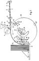
- the torn off sections are then provided on the folding pliers cylinder 30 with folded and glued bottoms and placed vertically on the stacking table 31 for their collection or stacking.
- the folding pliers cylinder 30 is provided with three so-called folding beam abutments 12, 12 ', 12' 'which cooperate like pliers with the pivotable folding pliers jaws 13, 13', which can be pivoted about pivot axes 14 mounted on the folding pliers cylinder 30 and in the direction by springs, not shown are applied to their closed position.
- actuating levers 15 which carry cam rollers 16 at the ends.
- the cam rollers 16 run onto a control cam 17 which is fixed to the frame and which opens the folding tongs to release the folded bottoms before the bags or sacks are set down, as can be seen from the folding tongs 12 ', 13'.
- a suction pipe 32 is pivotally mounted eccentrically to the axis of rotation 20 in the folding pinch cylinder 30, the pivot axis 19 of which extends parallel to the folding pin axis 20.
- the suction pipe 22 is provided with an actuating lever 21 which carries a cam roller 22 at the end.
- Suction pipes 18 are connected to the suction pipe 32 in a radial plane and carry suction nozzles 33 at the end.
- the suction tubes 18 are connected to tension springs 25, the other ends of which are firmly connected to the folding pincer cylinder by means of pins 26 are. By means of the tension springs 25, the suction tubes 18 are held in abutment against folding jaw cylinders, fixed stops 24 or acted upon in the direction thereof.
- the cam rollers 22 of the levers 21 actuating the suction cup run on control cams 23 over part of their rotation, the curve characteristic of the control curve 23 and the eccentricity of the axis 19 of the suction pipe 22 being selected such that the suction nozzles 33 emerge from the cylinder surface of the folding pliers cylinder 30 move out as soon as the suction nozzles 33 are located approximately vertically above the storage table 33, and then execute an approximately tangential movement which is perpendicular to the footprint of the storage table 31.
- the storage table 31 is arranged on the folding pliers cylinder 30 below its horizontal diameter plane and has vertically projecting deflecting fingers 36 which engage in circumferential grooves of the folding pliers cylinder.
- a folding knife cylinder 7 is provided on the folding pliers cylinder 30, which is provided with a folding knife 11 running along a surface line. Immediately behind the folding knife 11, the folding knife cylinder 7 is provided with a stamp 10, which removes a glue strip from a glue roller 8, which closes a glue box 9, and transfers it in format to the bag workpieces.
- the bags provided and conveyed in this way on the folding pliers cylinder with folded and glued bottoms are then sucked in by the suction nozzles 33 when they continue to move if they emerge from the enveloping cylinder of the folding jaw cylinder due to the control of the suction tube 32 and the eccentricity of the axis of the suction tube 32.
- the suction tubes 18 execute a movement which delays the sacks or bags being sucked in, so that they are deposited on the stacking table 31 at a speed which is delayed to zero or almost to zero.
- the suction air supply to the suction cups 33 is controlled in such a way that they suck the bag workpieces approximately in an area in which the suction cups lie horizontally.
- the folding tongs 12, 13 open so that the folded bottoms detach from the folding tongs cylinder and the suction cups take over the further delayed transport of the bags until they are placed on the tray table 31.
- the approximately tangential, delayed conveyance of the sacks by the suction cups means that they are securely placed behind the deflecting fingers 36 on the support surface of the stacking table 31.
- Suction cups are assigned to each of the three folding pliers, of which only one is shown in the drawing.
- the vacuum acting on the suction tubes 18 is preferably activated shortly before the folding tongs open. The vacuum is then switched off again shortly before the bags are placed on the stacking table 31.
- the folding pliers cylinder 30 is constructed in the same way as the folding pliers cylinder according to FIGS. 1 and 2 with regard to the folding pliers and their control.
- the exemplary embodiment according to FIG. 3 differs from that according to FIGS. 1 and 2 in that, instead of the suction pipes pivotable about eccentric axes, a suction belt 40 is provided, the conveyor run 41 of which is via a suction box 42 is running.
- a plurality of suction belts 40 are expediently provided, which, as can be seen from FIG. 3, engage in circumferential grooves of the folding pliers cylinder 30.
- the ends provided with the folded bottoms run up after their release from the folding tongs onto the suction belt 40, wherein they are then sucked in by the conveying strands 41 as soon as they run over the suction boxes 42.
- the suction belts 40 and the suction boxes 42 are controlled in such a way that the sucked-in bags are decelerated to zero or almost zero speed. Shortly before the bags are placed on the stacking table 31, the suction air supply to the suction boxes 12 is switched off.
- the suction belt conveyors 40 are arranged stationary in the machine frame.
- a spring-loaded transport roller 44 is set against the folding tongs cylinder 30.
- the distance between the transport roller 44 and the upper deflection roller 45 of the suction belt conveyor or 40 is greater than the length of a sack, so that proper conveyance is ensured until the leading ends of the sacks provided with the folded bottoms emerge on the suction belt conveyor 40.
Landscapes
- Engineering & Computer Science (AREA)
- Mechanical Engineering (AREA)
- Making Paper Articles (AREA)
- Separation, Sorting, Adjustment, Or Bending Of Sheets To Be Conveyed (AREA)
- Pile Receivers (AREA)
- Delivering By Means Of Belts And Rollers (AREA)
Applications Claiming Priority (2)
| Application Number | Priority Date | Filing Date | Title |
|---|---|---|---|
| DE4123399A DE4123399A1 (de) | 1991-07-15 | 1991-07-15 | Vorrichtung zum sammeln oder stapeln von flachen werkstuecken auf einem stapeltisch |
| DE4123399 | 1991-07-15 |
Publications (2)
| Publication Number | Publication Date |
|---|---|
| EP0528126A1 true EP0528126A1 (fr) | 1993-02-24 |
| EP0528126B1 EP0528126B1 (fr) | 1995-12-06 |
Family
ID=6436183
Family Applications (1)
| Application Number | Title | Priority Date | Filing Date |
|---|---|---|---|
| EP92109388A Expired - Lifetime EP0528126B1 (fr) | 1991-07-15 | 1992-06-03 | Dispositif pour le rassemblement ou l'empilage de pièces plates sur une table d'empilage |
Country Status (4)
| Country | Link |
|---|---|
| US (1) | US5308056A (fr) |
| EP (1) | EP0528126B1 (fr) |
| JP (1) | JP3354962B2 (fr) |
| DE (2) | DE4123399A1 (fr) |
Cited By (1)
| Publication number | Priority date | Publication date | Assignee | Title |
|---|---|---|---|---|
| EP0673868A3 (fr) * | 1994-03-18 | 1996-02-07 | Xerox Corp | Dispositif de retournement et d'empilage à disque avec une agrafeuse intégrée. |
Families Citing this family (9)
| Publication number | Priority date | Publication date | Assignee | Title |
|---|---|---|---|---|
| DE4318473A1 (de) * | 1993-06-03 | 1994-12-08 | Arsoma Druckmaschinen Gmbh | Stapelvorrichtung |
| US5409201A (en) * | 1994-03-18 | 1995-04-25 | Xerox Corporation | Integral disk type inverter-stacker and stapler with sheet stacking control |
| DE4417121C1 (de) * | 1994-05-16 | 1995-10-05 | Windmoeller & Hoelscher | Vorrichtung zum Stapeln flacher Werkstücke, vorzugsweise von Papierbeuteln |
| DE29822224U1 (de) * | 1998-12-14 | 1999-02-04 | Pfankuch Maschinen GmbH, 22926 Ahrensburg | Vorrichtung zum Sammeln und Übergeben von Papierzuschnitten o.dgl. |
| EP1352865B1 (fr) * | 2002-04-12 | 2011-09-28 | Kabushiki Kaisha Toshiba | Dispositif d'empilage de feuilles |
| US7306222B2 (en) * | 2003-05-14 | 2007-12-11 | Goss International Americas, Inc. | Sheet material feeder |
| US8302955B2 (en) * | 2005-06-17 | 2012-11-06 | Hewlett-Packard Development Company, L.P. | Rotating vacuum fingers for removal of printing media from an impression drum |
| DE102006029140B3 (de) * | 2006-06-24 | 2008-01-03 | Windmöller & Hölscher Kg | Vorrichtung und Verfahren zum Anordnen von flachen Werkstücken auf einem Sammeltisch |
| IL240822B (en) * | 2014-09-23 | 2020-03-31 | Heidelberger Druckmasch Ag | Sheet feeding device |
Citations (9)
| Publication number | Priority date | Publication date | Assignee | Title |
|---|---|---|---|---|
| DE517004C (de) * | 1930-01-23 | 1931-02-04 | Koenig & Bauer Schnellpressfab | Bogenausfuehrvorrichtung an Haltzylinderschnellpressen |
| US2087704A (en) * | 1935-09-12 | 1937-07-20 | Potdevin Machine Co | Bag making machine |
| GB857769A (en) * | 1958-02-20 | 1961-01-04 | Smithe Machine Co Inc F L | Envelope blank feeding apparatus |
| US3105422A (en) * | 1959-05-22 | 1963-10-01 | Fmc Corp | Bag stacking mechanism |
| US3338575A (en) * | 1965-03-10 | 1967-08-29 | Paper Converting Machine Co | Web lapping apparatus |
| CH454177A (fr) * | 1966-06-28 | 1968-04-15 | Creusot Forges Ateliers | Dispositif ralentisseur de sortie, pour machines à imprimer |
| US3865362A (en) * | 1973-02-23 | 1975-02-11 | Miller Printing Machinery Co | Sheet transfer cylinder |
| DE3347864A1 (de) * | 1983-06-28 | 1985-05-23 | Windmöller & Hölscher, 4540 Lengerich | Vorrichtung zum stapeln flacher werkstuecke |
| EP0365848A2 (fr) * | 1988-10-25 | 1990-05-02 | Heidelberger Druckmaschinen Aktiengesellschaft | Dispositif ralentisseur de sortie pour une machine pour imprimer des feuilles |
Family Cites Families (8)
| Publication number | Priority date | Publication date | Assignee | Title |
|---|---|---|---|---|
| US2130841A (en) * | 1936-06-09 | 1938-09-20 | Cottrell C B & Sons Co | Delivery mechanism for printing presses |
| US2113650A (en) * | 1936-11-18 | 1938-04-12 | Miehle Printing Press & Mfg | Sheet delivery device |
| US3730517A (en) * | 1971-05-03 | 1973-05-01 | Harris Intertype Corp | Sheet conveyor apparatus and method |
| GB1521317A (en) * | 1975-09-16 | 1978-08-16 | De La Rue Crosfield | Stacking apparatus for flexible sheets |
| US4132403A (en) * | 1977-07-07 | 1979-01-02 | Veb Polygraph Leipzig Kombinat Fuer Polygraphische Maschinen Und Ausruestungen | Sheet transfer apparatus for printing machine |
| DE3404459A1 (de) * | 1984-02-08 | 1985-08-14 | Frankenthal Ag Albert | Verfahren und vorrichtung zur auslage bogenfoermiger produkte in form eines schuppenstromes |
| US5141221A (en) * | 1990-11-05 | 1992-08-25 | Heidelberg Harris Gmbh | Deceleration device in the folder of a rotary printing machine |
| DE4223555A1 (de) * | 1991-08-12 | 1993-02-18 | Koenig & Bauer Ag | Trommel zum transportieren von bogen |
-
1991
- 1991-07-15 DE DE4123399A patent/DE4123399A1/de not_active Withdrawn
-
1992
- 1992-06-03 DE DE59204567T patent/DE59204567D1/de not_active Expired - Fee Related
- 1992-06-03 EP EP92109388A patent/EP0528126B1/fr not_active Expired - Lifetime
- 1992-07-10 JP JP18411092A patent/JP3354962B2/ja not_active Expired - Fee Related
- 1992-07-15 US US07/913,420 patent/US5308056A/en not_active Expired - Lifetime
Patent Citations (9)
| Publication number | Priority date | Publication date | Assignee | Title |
|---|---|---|---|---|
| DE517004C (de) * | 1930-01-23 | 1931-02-04 | Koenig & Bauer Schnellpressfab | Bogenausfuehrvorrichtung an Haltzylinderschnellpressen |
| US2087704A (en) * | 1935-09-12 | 1937-07-20 | Potdevin Machine Co | Bag making machine |
| GB857769A (en) * | 1958-02-20 | 1961-01-04 | Smithe Machine Co Inc F L | Envelope blank feeding apparatus |
| US3105422A (en) * | 1959-05-22 | 1963-10-01 | Fmc Corp | Bag stacking mechanism |
| US3338575A (en) * | 1965-03-10 | 1967-08-29 | Paper Converting Machine Co | Web lapping apparatus |
| CH454177A (fr) * | 1966-06-28 | 1968-04-15 | Creusot Forges Ateliers | Dispositif ralentisseur de sortie, pour machines à imprimer |
| US3865362A (en) * | 1973-02-23 | 1975-02-11 | Miller Printing Machinery Co | Sheet transfer cylinder |
| DE3347864A1 (de) * | 1983-06-28 | 1985-05-23 | Windmöller & Hölscher, 4540 Lengerich | Vorrichtung zum stapeln flacher werkstuecke |
| EP0365848A2 (fr) * | 1988-10-25 | 1990-05-02 | Heidelberger Druckmaschinen Aktiengesellschaft | Dispositif ralentisseur de sortie pour une machine pour imprimer des feuilles |
Cited By (1)
| Publication number | Priority date | Publication date | Assignee | Title |
|---|---|---|---|---|
| EP0673868A3 (fr) * | 1994-03-18 | 1996-02-07 | Xerox Corp | Dispositif de retournement et d'empilage à disque avec une agrafeuse intégrée. |
Also Published As
| Publication number | Publication date |
|---|---|
| DE59204567D1 (de) | 1996-01-18 |
| DE4123399A1 (de) | 1993-01-21 |
| JP3354962B2 (ja) | 2002-12-09 |
| EP0528126B1 (fr) | 1995-12-06 |
| JPH05193808A (ja) | 1993-08-03 |
| US5308056A (en) | 1994-05-03 |
Similar Documents
| Publication | Publication Date | Title |
|---|---|---|
| DE69212348T2 (de) | Seitenfaltvorrichtung mit Unterdruck für Umschlagfaltapparat | |
| EP0919471B1 (fr) | Dispositif pour manipuler des emballages | |
| EP0606550B1 (fr) | Dispositif pour transporter les objets plats à un dispositif de traitement de produit imprimé | |
| DE10235929C5 (de) | Vorrichtung zum Befüllen von Standbodenbeuteln | |
| DE60224714T2 (de) | Verfahren zum Verpacken von Zigaretten in Weichpackungen | |
| EP0528126B1 (fr) | Dispositif pour le rassemblement ou l'empilage de pièces plates sur une table d'empilage | |
| DE2526432A1 (de) | Verfahren und vorrichtung zum speichern und zufuehren von ventilsaekken zu fuellmaschinen | |
| DE3603285A1 (de) | Zusammentragmaschine | |
| DE2162874B2 (de) | Einrichtung zum Kleben eines Scheitelstreifens aus Kautschuk auf einen Wulstring für Luftreifen | |
| EP0133511B1 (fr) | Dispositif pour l'alimentation en feuilles à une station d'emballage | |
| DE3131268C2 (de) | Verfahren und Vorrichtung zum Zuführen von Banderolen zu einer Packung | |
| DE3818910A1 (de) | Vorrichtung zum fuellen und verschliessen von offenen saecken | |
| WO2009121542A1 (fr) | Équipement et procédé de fabrication de sacs à partir de tronçons de tube souple | |
| DE1761880B1 (de) | Verfahren und Vorrichtung zum Aufbringen von Papier- oder Kunststofftraggriffen auf eine Werkstoffbahn | |
| DE3314619C2 (de) | Vorrichtung zum Öffnen von aus mehreren Lagen bestehenden Falzbogen | |
| DE1178772B (de) | Vorrichtung zum paketweisen Gruppieren und Banderolieren von Briefumschlaegen | |
| DE60018008T2 (de) | Verfahren und vorrichtung zum kontinuierlichen umhüllen von gegenständen | |
| DE2112353B2 (de) | Verfahren und Vorrichtung zum Trennen einer schuppenförmigen Folge von von einer Schlauchziehmaschine hergestellten Schlauchabschnitten für das Bilden von abgezählten Stapel a | |
| DE19627158C2 (de) | Vorrichtung zum Vereinzeln von Stapeln aus flachliegenden Säcken mit in die Sackebene gefalteten Böden | |
| DE2109709A1 (de) | Verfahren und Vorrichtung zum Übergeben von Werk stucken von einem Forderer an einen folgenden, insbeson dere von Packmaterialzuschmtten bei Packmaschinen | |
| DE1067672B (de) | Vorrichtung zum UEberfuehren von Werkstuecken in einer Maschine zum Umhuellen von Schachtelkoerpern | |
| DE3735815C1 (en) | Device for depositing or stacking successively conveyed flat workpieces | |
| DE1228504B (de) | Verfahren und Vorrichtung zum Herstellen der Boeden von Klotzbodenbeuteln | |
| DE972134C (de) | Streifenaufklebmaschine | |
| DE1025709B (de) | Verfahren und Maschine zur Bildung eines Ventil-Kreuzbodens an dem offenen Ende eines aus Papier od. dgl. bestehenden Kreuzbodenbeutels |
Legal Events
| Date | Code | Title | Description |
|---|---|---|---|
| PUAI | Public reference made under article 153(3) epc to a published international application that has entered the european phase |
Free format text: ORIGINAL CODE: 0009012 |
|
| AK | Designated contracting states |
Kind code of ref document: A1 Designated state(s): DE FR GB IT |
|
| 17P | Request for examination filed |
Effective date: 19930726 |
|
| 17Q | First examination report despatched |
Effective date: 19940727 |
|
| GRAA | (expected) grant |
Free format text: ORIGINAL CODE: 0009210 |
|
| AK | Designated contracting states |
Kind code of ref document: B1 Designated state(s): DE FR GB IT |
|
| GBT | Gb: translation of ep patent filed (gb section 77(6)(a)/1977) |
Effective date: 19951207 |
|
| REF | Corresponds to: |
Ref document number: 59204567 Country of ref document: DE Date of ref document: 19960118 |
|
| ITF | It: translation for a ep patent filed | ||
| ET | Fr: translation filed | ||
| PLBE | No opposition filed within time limit |
Free format text: ORIGINAL CODE: 0009261 |
|
| STAA | Information on the status of an ep patent application or granted ep patent |
Free format text: STATUS: NO OPPOSITION FILED WITHIN TIME LIMIT |
|
| 26N | No opposition filed | ||
| REG | Reference to a national code |
Ref country code: GB Ref legal event code: IF02 |
|
| PGFP | Annual fee paid to national office [announced via postgrant information from national office to epo] |
Ref country code: GB Payment date: 20040528 Year of fee payment: 13 |
|
| PGFP | Annual fee paid to national office [announced via postgrant information from national office to epo] |
Ref country code: FR Payment date: 20040618 Year of fee payment: 13 |
|
| PGFP | Annual fee paid to national office [announced via postgrant information from national office to epo] |
Ref country code: DE Payment date: 20040630 Year of fee payment: 13 |
|
| PG25 | Lapsed in a contracting state [announced via postgrant information from national office to epo] |
Ref country code: IT Free format text: LAPSE BECAUSE OF NON-PAYMENT OF DUE FEES Effective date: 20050603 Ref country code: GB Free format text: LAPSE BECAUSE OF NON-PAYMENT OF DUE FEES Effective date: 20050603 |
|
| PG25 | Lapsed in a contracting state [announced via postgrant information from national office to epo] |
Ref country code: DE Free format text: LAPSE BECAUSE OF NON-PAYMENT OF DUE FEES Effective date: 20060103 |
|
| PG25 | Lapsed in a contracting state [announced via postgrant information from national office to epo] |
Ref country code: FR Free format text: LAPSE BECAUSE OF NON-PAYMENT OF DUE FEES Effective date: 20060228 |
|
| GBPC | Gb: european patent ceased through non-payment of renewal fee |
Effective date: 20050603 |
|
| REG | Reference to a national code |
Ref country code: FR Ref legal event code: ST Effective date: 20060228 |