EP0521411A1 - Abgasleitung einer Brennkraftmaschine - Google Patents
Abgasleitung einer Brennkraftmaschine Download PDFInfo
- Publication number
- EP0521411A1 EP0521411A1 EP92110852A EP92110852A EP0521411A1 EP 0521411 A1 EP0521411 A1 EP 0521411A1 EP 92110852 A EP92110852 A EP 92110852A EP 92110852 A EP92110852 A EP 92110852A EP 0521411 A1 EP0521411 A1 EP 0521411A1
- Authority
- EP
- European Patent Office
- Prior art keywords
- exhaust pipe
- internal combustion
- combustion engine
- throttle element
- pipe according
- Prior art date
- Legal status (The legal status is an assumption and is not a legal conclusion. Google has not performed a legal analysis and makes no representation as to the accuracy of the status listed.)
- Ceased
Links
Images
Classifications
-
- F—MECHANICAL ENGINEERING; LIGHTING; HEATING; WEAPONS; BLASTING
- F01—MACHINES OR ENGINES IN GENERAL; ENGINE PLANTS IN GENERAL; STEAM ENGINES
- F01N—GAS-FLOW SILENCERS OR EXHAUST APPARATUS FOR MACHINES OR ENGINES IN GENERAL; GAS-FLOW SILENCERS OR EXHAUST APPARATUS FOR INTERNAL COMBUSTION ENGINES
- F01N3/00—Exhaust or silencing apparatus having means for purifying, rendering innocuous, or otherwise treating exhaust
- F01N3/08—Exhaust or silencing apparatus having means for purifying, rendering innocuous, or otherwise treating exhaust for rendering innocuous
- F01N3/10—Exhaust or silencing apparatus having means for purifying, rendering innocuous, or otherwise treating exhaust for rendering innocuous by thermal or catalytic conversion of noxious components of exhaust
- F01N3/18—Exhaust or silencing apparatus having means for purifying, rendering innocuous, or otherwise treating exhaust for rendering innocuous by thermal or catalytic conversion of noxious components of exhaust characterised by methods of operation; Control
- F01N3/20—Exhaust or silencing apparatus having means for purifying, rendering innocuous, or otherwise treating exhaust for rendering innocuous by thermal or catalytic conversion of noxious components of exhaust characterised by methods of operation; Control specially adapted for catalytic conversion ; Methods of operation or control of catalytic converters
- F01N3/2006—Periodically heating or cooling catalytic reactors, e.g. at cold starting or overheating
-
- F—MECHANICAL ENGINEERING; LIGHTING; HEATING; WEAPONS; BLASTING
- F02—COMBUSTION ENGINES; HOT-GAS OR COMBUSTION-PRODUCT ENGINE PLANTS
- F02D—CONTROLLING COMBUSTION ENGINES
- F02D9/00—Controlling engines by throttling air or fuel-and-air induction conduits or exhaust conduits
- F02D9/04—Controlling engines by throttling air or fuel-and-air induction conduits or exhaust conduits concerning exhaust conduits
-
- F—MECHANICAL ENGINEERING; LIGHTING; HEATING; WEAPONS; BLASTING
- F01—MACHINES OR ENGINES IN GENERAL; ENGINE PLANTS IN GENERAL; STEAM ENGINES
- F01N—GAS-FLOW SILENCERS OR EXHAUST APPARATUS FOR MACHINES OR ENGINES IN GENERAL; GAS-FLOW SILENCERS OR EXHAUST APPARATUS FOR INTERNAL COMBUSTION ENGINES
- F01N2260/00—Exhaust treating devices having provisions not otherwise provided for
- F01N2260/14—Exhaust treating devices having provisions not otherwise provided for for modifying or adapting flow area or back-pressure
-
- Y—GENERAL TAGGING OF NEW TECHNOLOGICAL DEVELOPMENTS; GENERAL TAGGING OF CROSS-SECTIONAL TECHNOLOGIES SPANNING OVER SEVERAL SECTIONS OF THE IPC; TECHNICAL SUBJECTS COVERED BY FORMER USPC CROSS-REFERENCE ART COLLECTIONS [XRACs] AND DIGESTS
- Y02—TECHNOLOGIES OR APPLICATIONS FOR MITIGATION OR ADAPTATION AGAINST CLIMATE CHANGE
- Y02T—CLIMATE CHANGE MITIGATION TECHNOLOGIES RELATED TO TRANSPORTATION
- Y02T10/00—Road transport of goods or passengers
- Y02T10/10—Internal combustion engine [ICE] based vehicles
- Y02T10/12—Improving ICE efficiencies
Definitions
- the invention relates to an exhaust pipe of an internal combustion engine according to the preamble of claim 1.
- a throttle element made of bimetal for the exhaust pipe of an internal combustion engine which releases the full cross section of an exhaust pipe at low exhaust gas temperature and swivels a baffle element into the exhaust gas stream at higher temperatures.
- the invention has for its object to provide an exhaust pipe of an internal combustion engine with a catalyst in which the catalyst reaches its working temperature in the shortest possible time after starting the internal combustion engine.
- the arrangement of a throttle element in the exhaust pipe which reduces the cross section of the exhaust pipe to a remaining gap in a cold internal combustion engine, increases the exhaust gas back pressure. To compensate for this increased back pressure, the engine mass flow is increased, which increases the exhaust gas temperature and the catalytic converter reaches its working temperature more quickly.
- the throttle element is designed, for example, as a bimetal or memory metal and is arranged with its upstream, fixed end adjacent to a side wall of the exhaust pipe. The downstream, free end forms a gap with the cold opposite side wall. The throttle element thus blocks the exhaust pipe in the cold state except for the gap required to flow off the amount of exhaust gas occurring in the cold start phase.
- the elasticity of the throttle element is designed so that the throttle element increases the gap with a cold start and an immediate, high load of the exhaust gas flow.
- This arrangement is advantageously self-regulating, so that no sensors or control elements are required. It is of simple, maintenance-free construction and is preferably arranged downstream of the catalyst, as a result of which the catalyst is heated in an optimally short time.
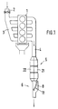
- An internal combustion engine 1 has an intake air distributor 3 controlled by a throttle valve 2 and an exhaust gas line 4 with a catalytic converter 5. The direction of flow of the exhaust gases is shown by arrows. Downstream of the catalytic converter 5, a section 6 of the otherwise circular exhaust pipe 4 is rectangular. This section 6 has, next to a side wall 7, a bulge 8, in the upstream end of which a holder 9 is arranged.
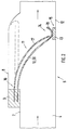
- This bracket 9 receives a fixed end 10 of a throttle element designed as a bimetallic plate 11, which extends from the bracket 9 to close the exhaust pipe 4 almost completely to an opposite side wall 12.
- a stop 13 is arranged on the side wall 12, on which the downstream, movable end 14 lies on. The stop 13 leaves a gap 15 between the end 14 and the side wall 12, so that a minimum cross section of the exhaust pipe 4 remains free.
- the bimetallic sheet 11 is formed from two metal strips 16, 17 which are fastened at a distance from one another in the holder 9. At the end 14, a pocket 18 is formed on the metal strip 16, in which the metal strip 17 is guided.
- the free end 14 of the bimetal plate 11 is in the starting position shown in FIG. 2.
- the exhaust gas stream acts on the catalyst 5 undisturbed and heats it up comparatively quickly.
- This heating-up time is shortened by the position of the bimetal plate 11, since the exhaust gas back pressure for the internal combustion engine 1 is high due to the almost complete blocking of the exhaust line 4.
- the engine mass flow is increased, e.g. by an intervention on the throttle valve 2 or on an idle actuator, not shown.
- the increased throughput leads to faster heating of the internal combustion engine and thus to a reduction in pollutants
- the exhaust gas temperature and the exhaust gas mass flow increase.
- the rising temperature quickly heats the catalyst 5 and the bimetallic sheet 11, so that the free end 14 of the bimetallic sheet 11 lifts off the stop 13 and moves into the end position shown in dashed lines in FIG. 2. This movement is supported by the exhaust gas flow.
- a memory metal 20 can be used, which tilts suddenly from the starting position into the end position when a certain temperature is reached. If the temperature falls below this, the memory metal 20 tilts back into the starting position.
- Section 6 can be arranged upstream of the catalytic converter, for example, in the case of unfavorable installation conditions.
- the throttle element heats up rapidly since the exhaust gas stream acts directly on it.
- the bracket 9 can in the housing of e.g. catalyst 5 made from two half-shells 21, 22 can be integrated in a half-shell 21.
Landscapes
- Engineering & Computer Science (AREA)
- Chemical & Material Sciences (AREA)
- Chemical Kinetics & Catalysis (AREA)
- Combustion & Propulsion (AREA)
- Mechanical Engineering (AREA)
- General Engineering & Computer Science (AREA)
- Health & Medical Sciences (AREA)
- Toxicology (AREA)
- Exhaust Gas After Treatment (AREA)
- Control Of Throttle Valves Provided In The Intake System Or In The Exhaust System (AREA)
- Temperature-Responsive Valves (AREA)
- Exhaust Silencers (AREA)
Abstract
Hinter dem in einer Abgasleitung (4) einer Brennkraftmaschine (1) angeordneten Katalysator (5) ist ein selbstregelndes Drosselelement (8) angeordnet, welches in der Warmlaufphase der Brennkraftmaschine (1) die Abgasleitung (4) nahezu vollständig verschließt. Der dadurch erhöhte Abgasgegendruck bewirkt einen größeren Motormassendurchsatz, wodurch die Abgastemperatur steigt und der Katalysator zügig erwärmt wird. <IMAGE>
Description
- Die Erfindung betrifft eine Abgasleitung einer Brennkraftmaschine gemäß dem Oberbegriff des Patentanspruches 1.
- Aus der DE-OS 23 21 578 ist ein Drosselelement aus Bimetall für die Abgasleitung einer Brennkraftmaschine bekannt, welches bei niedriger Abgastemperatur den vollen Querschnitt einer Abgasleitung freigibt und bei höheren Temperaturen ein Stauelement in den Abgasstrom schwenkt. Mit dieser Anordnung soll eine schnellere Aufheizung der Kernzone des Katalysators nach dem Start der Brennkraftmaschine und eine gleichmäßige, lebensdauererhöhende Beaufschlagung des Katalysators nach dem Erreichen seiner Arbeitstemperatur erzielt werden.
- Der Erfindung liegt die Aufgabe zugrunde, eine Abgasleitung einer Brennkraftmaschine mit einem Katalysator zu schaffen, in der der Katalysator nach dem Anlassen der Brennkraftmaschine in möglichst kurzer Zeit seine Arbeitstemperatur erreicht.
- Die Lösung dieser Aufgabe gelingt mit den Merkmalen des Patentanspruches 1. Vorteilhafte Ausgestaltungen der Erfindung sind in den Unteransprüchen benannt.
- Durch die Anordnung eines Drosselelementes in der Abgasleitung, welches bei kalter Brennkraftmaschine den Querschnitt der Abgasleitung bis auf einen verbleibenden Spalt reduziert, wird der Abgasgegendruck erhöht. Zur Kompensation dieses erhöhten Gegendruckes wird der Motormassendurchsatz erhöht, wodurch die Abgastemperatur steigt und der Katalysator schneller seine Arbeitstemperatur erreicht. Das Drosselelement ist z.B. als Bimetall oder Memorymetall ausgebildet und mit seinem stromauf liegenden, ortsfesten Ende benachbart einer Seitenwandung der Abgasleitung angeordnet. Das stromab liegende, freie Ende bildet in kaltem Zustand einen Spalt mit der gegenüberliegenden Seitenwandung. Das Drosselelement versperrt somit im kalten Zustand die Abgasleitung bis auf den zum Abströmen der in der Kaltstartphase anfallenden Abgasmenge erforderlichen Spalt. Mit dem Warmlaufen der Brennkraftmaschine erhöht sich die Abgastemperatur, wodurch sich das Drosselelement verformt und dabei fortschreitend den gesamten Querschnitt der Abgasleitung freigibt. Die Elastizität des Drosselelementes ist so ausgelegt, daß bei einem Kaltstart und sofortiger, hoher Last der Abgasstrom das Drosselelement den Spalt vergrößernd anhebt.
- Vorteilhafterweise ist diese Anordnung selbstregelnd, so daß keinerlei Sensoren oder Steuerelemente erforderlich sind. Sie ist von einfachem, wartungsfreiem Aufbau und ist bevorzugt stromab des Katalysators angeordnet, wodurch der Katalysator in optimal kurzer Zeit erwärmt wird.
- Die Erfindung wird anhand von Figuren beispielhaft näher erläutert.
- Es zeigen:
- Fig. 1
- eine schematische Ansicht einer Abgasleitung an einer Brennkraftmaschine und
- Fig. 2
- einen schematischen Schnitt durch einen Teil der Abgasleitung gemäß Fig. 1.
- Eine Brennkraftmaschine 1 weist einen von einer Drosselklappe 2 beherrschten Ansaugluftverteiler 3 und eine Abgasleitung 4 mit einem Katalysator 5 auf. Die Strömungsrichtung der Abgase ist durch Richtungspfeile dargestellt. Stromab des Katalysators 5 ist ein Abschnitt 6 der ansonsten kreisförmigen Abgasleitung 4 rechteckig ausgeführt. Dieser Abschnitt 6 weist benachbart einer Seitenwandung 7 eine Ausbuchtung 8 auf, in deren stromauf liegendem Ende eine Halterung 9 angeordnet ist.
- Diese Halterung 9 nimmt ein ortsfestes Ende 10 eines als Bimetallblech 11 ausgeführten Drosselelementes auf, welches sich von der Halterung 9 aus die Abgasleitung 4 nahezu vollständig verschließend bis zu einer gegenüberliegenden Seitenwandung 12 erstreckt. An der Seitenwandung 12 ist ein Anschlag 13 angeordnet, auf dem das stromab liegende, bewegliche Ende 14 aufliegt. Der Anschlag 13 beläßt einen Spalt 15 zwischen dem Ende 14 und der Seitenwandung 12, so daß ein Mindestquerschnitt der Abgasleitung 4 frei bleibt.
- Das Bimetallblech 11 wird aus zwei Metallstreifen 16, 17 gebildet, die beabstandet zueinander in der Halterung 9 befestigt sind. Am Ende 14 ist an dem Metallstreifen 16 eine Tasche 18 angeformt, in der der Metallstreifen 17 geführt ist.
- Unmittelbar nach dem Start der Brennkraftmaschine 1 ist die Abgastemperatur relativ niedrig, das freie Ende 14 des Bimetallbleches 11 befindet sich in der in Fig. 2 gezeigten Ausgangsstellung. Der Abgasstrom beaufschlagt den Katalysator 5 ungestört und heizt ihn vergleichsweise schnell auf. Diese Aufheizzeit wird durch die Stellung des Bimetallbleches 11 verkürzt, da durch das nahezu vollständige Versperren der Abgasleitung 4 der Abgasgegendruck für die Brennkraftmaschine 1 hoch ist. Dieses führt zu einer erhöhten internen Abgasrückführung in den Überschneidungszeiten von Ein- und Auslaßventilen des Gaswechselsystemes und somit zu einer Schadstoffreduktion in der Warmlaufphase der Brennkraftmaschine. Zur Kompensation des erhöhten Abgasgegendruckes wird der Motormassendurchsatz erhöht, z.B. durch einen Eingriff an der Drosselklappe 2 oder an einem nicht gezeigten Leerlaufsteller. Der erhöhte Durchsatz führt einerseits zu einer schnelleren Erwärmung der Brennkraftmaschine und damit zu einer Reduzierung der Schadstoffe, andererseits steigt die Abgastemperatur und der Abgasmassenstrom. Die steigende Temperatur erwärmt den Katalysator 5 sowie das Bimetallblech 11 zügig, so daß das freie Ende 14 des Bimetallbleches 11 von dem Anschlag 13 abhebt und sich in die in Fig. 2 gestrichelt gezeigte Endstellung bewegt. Diese Bewegung wird durch den Abgasstrom unterstützt.
- Anstelle der Metallstreifen 16, 17 kann ein Memorymetall 20 verwendet werden, welches bei Erreichen einer bestimmten Temperatur ruckartig von der Ausgangsstellung in die Endstellung kippt. Wird diese Temperatur unterschritten, kippt das Memorymetall 20 in die Ausgangsstellung zurück.
- Der Abschnitt 6 kann z.B. bei ungünstigen Einbauverhältnissen vor dem Katalysator angeordnet sein. Hierbei erfolgt eine rasche Erwärmung des Drosselelementes, da es unmittelbar von dem Abgasstrom beaufschlagt wird.
- Die Halterung 9 kann in dem Gehäuse des z.B. aus zwei Halbschalen 21, 22 gefertigten Katalysators 5 in einer Halbschale 21 integriert sein.
Claims (8)
- Abgasleitung einer Brennkraftmaschine, mit mindestens einem in der Abgasleitung angeordneten Katalysator und einem in dieser angeordneten, verstellbaren Drosselelement, dadurch gekennzeichnet, daß das Drosselelement (Bimetallblech 11; Memorymetall 20) mit einem stromauf liegenden, ortsfesten Ende (10) benachbart einer Seitenwandung (7) der Abgasleitung (4) angeordnet ist und ein stromab liegendes, bewegliches Ende (14) bei kalter Brennkraftmaschine (1) einen Spalt (15) mit einer gegenüberliegenden Seitenwandung (12) bildend angeordnet ist.
- Abgasleitung nach Anspruch 1, dadurch gekennzeichnet, daß das Drosselelement (Bimetallblech 11; Memorymetall 20) mittels einer Halterung (9) mit seinem ortsfesten Ende (10) in einer Ausbuchtung (8) der Seitenwandung (7) gehalten ist.
- Abgasleitung nach Anspruch 1, dadurch gekennzeichnet, daß das Bimetallblech (11) aus Metallstreifen (16, 17) besteht, wobei an dem beweglichen Ende (14) ein Metallstreifen (16) eine angeformte Tasche (18) zur Führung des anderen Metallstreifens (17) aufweist.
- Abgasleitung nach Anspruch 1, dadurch gekennzeichnet, daß das Bimetallblech (11) aus räumlich getrennt angeordneten Metallstreifen (16, 17) besteht, wobei an dem beweglichen Ende (14) ein Metallstreifen (16) eine angeformte Tasche (18) zur Führung des anderen Metallstreifens (17) aufweist.
- Abgasleitung nach Anspruch 1, dadurch gekennzeichnet, daß das Drosselelement (Bimetallblech 11; Memorymetall 20) stromab des Katalysators (5) angeordnet ist.
- Abgasleitung nach Anspruch 1, dadurch gekennzeichnet, daß das Gehäuse des Katalysators (5) aus Halbschalen (21, 22) geformt ist, wobei eine Halterung (9) für das Drosselelement (Bimetallblech 11; Memorymetall 20) in eine Halbschale (21 bzw. 22) integriert ist.
- Abgasleitung nach einem oder mehreren der vorhergehenden Ansprüche, dadurch gekennzeichnet, daß der Spalt (15) durch einen an der Seitenwandung (12) angeordneten Anschlag (13) gebildet ist.
- Abgasleitung nach Anspruch 1, dadurch gekennzeichnet, daß die Abgasleitung (4) im Bereich des Drosselelementes (Bimetall 11; Memorymetall 20) im Querschnitt rechteckig ausgeführt ist.
Applications Claiming Priority (2)
| Application Number | Priority Date | Filing Date | Title |
|---|---|---|---|
| DE4122141 | 1991-07-04 | ||
| DE4122141A DE4122141C2 (de) | 1991-07-04 | 1991-07-04 | Abgasleitung einer Brennkraftmaschine |
Publications (1)
| Publication Number | Publication Date |
|---|---|
| EP0521411A1 true EP0521411A1 (de) | 1993-01-07 |
Family
ID=6435420
Family Applications (1)
| Application Number | Title | Priority Date | Filing Date |
|---|---|---|---|
| EP92110852A Ceased EP0521411A1 (de) | 1991-07-04 | 1992-06-26 | Abgasleitung einer Brennkraftmaschine |
Country Status (4)
| Country | Link |
|---|---|
| US (1) | US5279117A (de) |
| EP (1) | EP0521411A1 (de) |
| JP (1) | JPH05240033A (de) |
| DE (1) | DE4122141C2 (de) |
Cited By (5)
| Publication number | Priority date | Publication date | Assignee | Title |
|---|---|---|---|---|
| WO2003066599A1 (de) * | 2002-02-02 | 2003-08-14 | Boehringer Ingelheim Pharma Gmbh & Co.Kg | N-allyloxyethyl-1,2,3,4,5,6-hexahydro-2,6-methano-3-benzazocine und ihre verwendung als arzneimittel |
| US6683089B2 (en) | 2002-02-02 | 2004-01-27 | Boehringer Ingelheim Pharma Gmbh & Co. Kg | N-allyoxyethyl-1,2,3,4,5,6-hexahydro-2,6-methano-3-benzazocine-10-ols |
| EP1544450A2 (de) * | 2003-12-20 | 2005-06-22 | DEUTZ Aktiengesellschaft | Abgasrückführ-Regelung mit mechanischer Temperaturregelung |
| EP1722175A2 (de) * | 2005-05-12 | 2006-11-15 | Behr GmbH & Co. KG | Differenzdruckventil |
| EP2071160A2 (de) | 2007-12-13 | 2009-06-17 | Ford Global Technologies, LLC | Steuerverfahren zur zeitlichen Erhöhung der Abgastemperatur |
Families Citing this family (14)
| Publication number | Priority date | Publication date | Assignee | Title |
|---|---|---|---|---|
| DE4302519C2 (de) * | 1993-01-29 | 2003-12-04 | Linde Ag | Abgasanlage für einen Verbrennungsmotor |
| DE19500472C2 (de) * | 1995-01-10 | 2003-10-16 | Schatz Thermo Gastech Gmbh | Verfahren zur Reduzierung der Abgasemissionen eines Verbrennungsmotors für Kraftfahrzeuge mit Abgaskatalysator |
| DE19518213A1 (de) * | 1995-05-18 | 1996-11-21 | Hermann Prof Dr Ing Krueger | Einrichtung zur Erhöhung der Konvertierung in einem katalytischen Konverter |
| JPH0949422A (ja) * | 1995-08-09 | 1997-02-18 | Denso Corp | 内燃機関の排出ガス浄化装置 |
| JP3824375B2 (ja) * | 1997-05-09 | 2006-09-20 | 日産ディーゼル工業株式会社 | ディーゼルエンジンの制御装置 |
| GB2335706A (en) * | 1998-03-25 | 1999-09-29 | Ford Global Tech Inc | I.c. engine exhaust system with cooled temporary storage reservoir |
| DE19911338A1 (de) | 1999-03-15 | 2000-09-21 | Volkswagen Ag | Brennkraftmaschine mit einer Abgasregelvorrichtung |
| JP3598894B2 (ja) * | 1999-07-28 | 2004-12-08 | トヨタ自動車株式会社 | 内燃機関の排気浄化装置 |
| AU2003238727A1 (en) * | 2003-04-30 | 2004-11-23 | H. Paulsen Undervisningsmetodikk As | Exhaust converter |
| GB0327401D0 (en) * | 2003-11-25 | 2003-12-31 | Emmett Malcolm D | Silencer for exhaust systems |
| US7793495B2 (en) * | 2007-05-18 | 2010-09-14 | International Truck Intellectual Property Company, Llc | Engine gas temperature reduction |
| JP5177401B2 (ja) * | 2008-05-30 | 2013-04-03 | 株式会社Ihi | 排気ガス浄化触媒の暖機方法及びシステム |
| US8935918B2 (en) * | 2010-04-23 | 2015-01-20 | GM Global Technology Operations LLC | Reconfigurable mixer for an exhaust aftertreatment system and method of using the same |
| EP3423684B1 (de) * | 2016-03-02 | 2020-05-06 | Watlow Electric Manufacturing Company | System zur axialen unterteilung von heizleistung |
Citations (3)
| Publication number | Priority date | Publication date | Assignee | Title |
|---|---|---|---|---|
| US3043095A (en) * | 1960-04-20 | 1962-07-10 | William J A Sturtz | Catalytic smog inhibitor |
| US3957447A (en) * | 1973-10-03 | 1976-05-18 | Toyota Jidosha Kogyo Kabushiki Kaisha | Catalytic convertor |
| EP0378797A1 (de) * | 1988-12-20 | 1990-07-25 | Emitec Gesellschaft für Emissionstechnologie mbH | Strömungsleitklappe aus Bimetall, insbesondere für Abgassysteme von Kraftfahrzeugen |
Family Cites Families (7)
| Publication number | Priority date | Publication date | Assignee | Title |
|---|---|---|---|---|
| US1483354A (en) * | 1919-11-25 | 1924-02-12 | Jr Frederick Kopper | Gas-engine muffler |
| AT233326B (de) * | 1962-07-12 | 1964-05-11 | Michael Guillermo Dipl Ing May | Verfahren und Einrichtung zur Verminderung der Anteile der unverbrannten und teilverbrannten Bestandteile in den Abgasen von fremdgezündeten Viertakt-Verbrennungskraftmaschinen |
| US3406515A (en) * | 1964-01-02 | 1968-10-22 | Texaco Inc | Internal combustion engine system for exhaust emissions control |
| DE2321578A1 (de) * | 1973-04-28 | 1974-11-14 | Porsche Ag | Katalytisches abgas-reinigungsgeraet |
| JPS5268625A (en) * | 1975-12-05 | 1977-06-07 | Mitsubishi Motors Corp | Thermal reactor |
| JPS6350631A (ja) * | 1986-08-20 | 1988-03-03 | Sekisui Chem Co Ltd | エンジン暖機装置 |
| DE8810816U1 (de) * | 1988-08-26 | 1989-12-21 | Emitec Gesellschaft für Emissionstechnologie mbH, 53797 Lohmar | Katalysator-Gehäuse, insbesondere für Startkatalysatoren, und zugehöriger Katalysator-Trägerkörper |
-
1991
- 1991-07-04 DE DE4122141A patent/DE4122141C2/de not_active Expired - Fee Related
-
1992
- 1992-06-26 EP EP92110852A patent/EP0521411A1/de not_active Ceased
- 1992-07-02 US US07/906,876 patent/US5279117A/en not_active Expired - Fee Related
- 1992-07-02 JP JP4175323A patent/JPH05240033A/ja active Pending
Patent Citations (3)
| Publication number | Priority date | Publication date | Assignee | Title |
|---|---|---|---|---|
| US3043095A (en) * | 1960-04-20 | 1962-07-10 | William J A Sturtz | Catalytic smog inhibitor |
| US3957447A (en) * | 1973-10-03 | 1976-05-18 | Toyota Jidosha Kogyo Kabushiki Kaisha | Catalytic convertor |
| EP0378797A1 (de) * | 1988-12-20 | 1990-07-25 | Emitec Gesellschaft für Emissionstechnologie mbH | Strömungsleitklappe aus Bimetall, insbesondere für Abgassysteme von Kraftfahrzeugen |
Non-Patent Citations (1)
| Title |
|---|
| PATENT ABSTRACTS OF JAPAN vol. 12, no. 269 (M-723)27. Juli 1988 & JP-A-63 050 631 ( SEKISUI CHEM CO LTD ) 3. März 1988 * |
Cited By (10)
| Publication number | Priority date | Publication date | Assignee | Title |
|---|---|---|---|---|
| WO2003066599A1 (de) * | 2002-02-02 | 2003-08-14 | Boehringer Ingelheim Pharma Gmbh & Co.Kg | N-allyloxyethyl-1,2,3,4,5,6-hexahydro-2,6-methano-3-benzazocine und ihre verwendung als arzneimittel |
| US6683089B2 (en) | 2002-02-02 | 2004-01-27 | Boehringer Ingelheim Pharma Gmbh & Co. Kg | N-allyoxyethyl-1,2,3,4,5,6-hexahydro-2,6-methano-3-benzazocine-10-ols |
| EP1544450A2 (de) * | 2003-12-20 | 2005-06-22 | DEUTZ Aktiengesellschaft | Abgasrückführ-Regelung mit mechanischer Temperaturregelung |
| EP1544450A3 (de) * | 2003-12-20 | 2007-08-22 | DEUTZ Aktiengesellschaft | Abgasrückführ-Regelung mit mechanischer Temperaturregelung |
| EP1722175A2 (de) * | 2005-05-12 | 2006-11-15 | Behr GmbH & Co. KG | Differenzdruckventil |
| EP1722175A3 (de) * | 2005-05-12 | 2007-09-19 | Behr GmbH & Co. KG | Differenzdruckventil |
| EP2071160A2 (de) | 2007-12-13 | 2009-06-17 | Ford Global Technologies, LLC | Steuerverfahren zur zeitlichen Erhöhung der Abgastemperatur |
| DE102007060142A1 (de) | 2007-12-13 | 2009-07-02 | Ford Global Technologies, LLC, Dearborn | Steuerverfahren zur zeitlichen Erhöhung der Abgastemperatur |
| DE102007060142B4 (de) * | 2007-12-13 | 2010-09-09 | Ford Global Technologies, LLC, Dearborn | Steuerverfahren zur zeitlichen Erhöhung der Abgastemperatur |
| US8245499B2 (en) | 2007-12-13 | 2012-08-21 | Ford Global Technologies, Llc | Control method for temporarily increasing the exhaust gas temperature |
Also Published As
| Publication number | Publication date |
|---|---|
| DE4122141C2 (de) | 1999-05-27 |
| JPH05240033A (ja) | 1993-09-17 |
| US5279117A (en) | 1994-01-18 |
| DE4122141A1 (de) | 1993-01-07 |
Similar Documents
| Publication | Publication Date | Title |
|---|---|---|
| DE4122141C2 (de) | Abgasleitung einer Brennkraftmaschine | |
| DE2629610C2 (de) | Vorrichtung zur Beheizung des Saugrohrs einer fremdgezündeten Brennkraftmaschine | |
| DE60020731T2 (de) | Kraftstoffrückführventil mit entlüftung | |
| DE102006015985A1 (de) | System zur Schadstoffbegrenzung für einen Motor | |
| DE2128989B2 (de) | Abgasreinigungsanlage für Brennkraftmaschinen | |
| DE3822954C2 (de) | Abgasrückführeinrichtung | |
| DE69206410T2 (de) | Abgassystem. | |
| DE2404112C3 (de) | Warmlaufeinrichtug für eine Brennkraftmaschine | |
| DE69426609T2 (de) | Vorrichtung zur katalytischen abgasreinigung | |
| DE2035772C3 (de) | Gleichdruckvergaser mit temperaturkontrollierter Gemischzufuhrung für Brennkraftmaschinen | |
| DE2903561A1 (de) | Vorrichtung zum betaetigen eines thermo-zeitventils bzw. -schalters | |
| DE9202798U1 (de) | Aufheizung einer einen Katalysator aufweisenden Trägermatrix mit einstellbarem Durchflußquerschnitt | |
| DE102012204161A1 (de) | Startautomatikvorrichtung für einen Verbrennungsmotor | |
| DE4129574C1 (de) | ||
| DE4130113A1 (de) | Katalysatoranordnung mit einer eingangsseitigen diffusorartigen gasleitvorrichtung | |
| DE4325004C2 (de) | Abgasreinigungsanlage zum Regeln bzw. Steuern des Gasdurchströmvolumens von Abgasreaktoren, insbesondere zur Reinigung der Abgase aus Brennkraftmaschinen | |
| CH615746A5 (en) | Arrangement for improving the efficiency of water central-heating installations | |
| DE4025267C2 (de) | Rückschlagventil für eine Gasleitung | |
| EP0378797B1 (de) | Strömungsleitklappe aus Bimetall, insbesondere für Abgassysteme von Kraftfahrzeugen | |
| DE3540013C1 (en) | Method for influencing the time taken to attain the starting temperature of a catalytic converter | |
| DE2539231C2 (de) | Vergasersystem für Brennkraftmaschine | |
| DE3012656C2 (de) | Vergaser | |
| DE3225016C2 (de) | Verbrennungsmotor mit Abgaskatalysator-Anlage und Steuervorrichtung zum automatischen Öffnen einer Starterklappe am Vergaser | |
| DE69003080T2 (de) | Vorrichtung zum Abführen und zur Reinigung von Auspuffgasen eines Motors. | |
| DE4113293A1 (de) | Temperaturabhaengig arbeitendes bypassventil |
Legal Events
| Date | Code | Title | Description |
|---|---|---|---|
| PUAI | Public reference made under article 153(3) epc to a published international application that has entered the european phase |
Free format text: ORIGINAL CODE: 0009012 |
|
| AK | Designated contracting states |
Kind code of ref document: A1 Designated state(s): DE ES FR GB IT SE |
|
| 17P | Request for examination filed |
Effective date: 19930511 |
|
| 17Q | First examination report despatched |
Effective date: 19930615 |
|
| STAA | Information on the status of an ep patent application or granted ep patent |
Free format text: STATUS: THE APPLICATION HAS BEEN REFUSED |
|
| 18R | Application refused |
Effective date: 19931121 |