EP1544450A2 - Abgasrückführ-Regelung mit mechanischer Temperaturregelung - Google Patents
Abgasrückführ-Regelung mit mechanischer Temperaturregelung Download PDFInfo
- Publication number
- EP1544450A2 EP1544450A2 EP04025856A EP04025856A EP1544450A2 EP 1544450 A2 EP1544450 A2 EP 1544450A2 EP 04025856 A EP04025856 A EP 04025856A EP 04025856 A EP04025856 A EP 04025856A EP 1544450 A2 EP1544450 A2 EP 1544450A2
- Authority
- EP
- European Patent Office
- Prior art keywords
- exhaust
- exhaust gas
- internal combustion
- combustion engine
- gas recirculation
- Prior art date
- Legal status (The legal status is an assumption and is not a legal conclusion. Google has not performed a legal analysis and makes no representation as to the accuracy of the status listed.)
- Withdrawn
Links
Images

Classifications
-
- F—MECHANICAL ENGINEERING; LIGHTING; HEATING; WEAPONS; BLASTING
- F02—COMBUSTION ENGINES; HOT-GAS OR COMBUSTION-PRODUCT ENGINE PLANTS
- F02D—CONTROLLING COMBUSTION ENGINES
- F02D21/00—Controlling engines characterised by their being supplied with non-airborne oxygen or other non-fuel gas
- F02D21/06—Controlling engines characterised by their being supplied with non-airborne oxygen or other non-fuel gas peculiar to engines having other non-fuel gas added to combustion air
- F02D21/08—Controlling engines characterised by their being supplied with non-airborne oxygen or other non-fuel gas peculiar to engines having other non-fuel gas added to combustion air the other gas being the exhaust gas of engine
-
- F—MECHANICAL ENGINEERING; LIGHTING; HEATING; WEAPONS; BLASTING
- F02—COMBUSTION ENGINES; HOT-GAS OR COMBUSTION-PRODUCT ENGINE PLANTS
- F02M—SUPPLYING COMBUSTION ENGINES IN GENERAL WITH COMBUSTIBLE MIXTURES OR CONSTITUENTS THEREOF
- F02M26/00—Engine-pertinent apparatus for adding exhaust gases to combustion-air, main fuel or fuel-air mixture, e.g. by exhaust gas recirculation [EGR] systems
- F02M26/13—Arrangement or layout of EGR passages, e.g. in relation to specific engine parts or for incorporation of accessories
- F02M26/22—Arrangement or layout of EGR passages, e.g. in relation to specific engine parts or for incorporation of accessories with coolers in the recirculation passage
- F02M26/29—Constructional details of the coolers, e.g. pipes, plates, ribs, insulation or materials
- F02M26/31—Air-cooled heat exchangers
-
- F—MECHANICAL ENGINEERING; LIGHTING; HEATING; WEAPONS; BLASTING
- F02—COMBUSTION ENGINES; HOT-GAS OR COMBUSTION-PRODUCT ENGINE PLANTS
- F02M—SUPPLYING COMBUSTION ENGINES IN GENERAL WITH COMBUSTIBLE MIXTURES OR CONSTITUENTS THEREOF
- F02M26/00—Engine-pertinent apparatus for adding exhaust gases to combustion-air, main fuel or fuel-air mixture, e.g. by exhaust gas recirculation [EGR] systems
- F02M26/45—Sensors specially adapted for EGR systems
- F02M26/46—Sensors specially adapted for EGR systems for determining the characteristics of gases, e.g. composition
- F02M26/47—Sensors specially adapted for EGR systems for determining the characteristics of gases, e.g. composition the characteristics being temperatures, pressures or flow rates
-
- F—MECHANICAL ENGINEERING; LIGHTING; HEATING; WEAPONS; BLASTING
- F02—COMBUSTION ENGINES; HOT-GAS OR COMBUSTION-PRODUCT ENGINE PLANTS
- F02D—CONTROLLING COMBUSTION ENGINES
- F02D29/00—Controlling engines, such controlling being peculiar to the devices driven thereby, the devices being other than parts or accessories essential to engine operation, e.g. controlling of engines by signals external thereto
- F02D29/06—Controlling engines, such controlling being peculiar to the devices driven thereby, the devices being other than parts or accessories essential to engine operation, e.g. controlling of engines by signals external thereto peculiar to engines driving electric generators
-
- F—MECHANICAL ENGINEERING; LIGHTING; HEATING; WEAPONS; BLASTING
- F02—COMBUSTION ENGINES; HOT-GAS OR COMBUSTION-PRODUCT ENGINE PLANTS
- F02D—CONTROLLING COMBUSTION ENGINES
- F02D41/00—Electrical control of supply of combustible mixture or its constituents
- F02D41/02—Circuit arrangements for generating control signals
- F02D41/14—Introducing closed-loop corrections
- F02D41/1438—Introducing closed-loop corrections using means for determining characteristics of the combustion gases; Sensors therefor
- F02D41/1444—Introducing closed-loop corrections using means for determining characteristics of the combustion gases; Sensors therefor characterised by the characteristics of the combustion gases
- F02D41/1446—Introducing closed-loop corrections using means for determining characteristics of the combustion gases; Sensors therefor characterised by the characteristics of the combustion gases the characteristics being exhaust temperatures
-
- F—MECHANICAL ENGINEERING; LIGHTING; HEATING; WEAPONS; BLASTING
- F02—COMBUSTION ENGINES; HOT-GAS OR COMBUSTION-PRODUCT ENGINE PLANTS
- F02M—SUPPLYING COMBUSTION ENGINES IN GENERAL WITH COMBUSTIBLE MIXTURES OR CONSTITUENTS THEREOF
- F02M26/00—Engine-pertinent apparatus for adding exhaust gases to combustion-air, main fuel or fuel-air mixture, e.g. by exhaust gas recirculation [EGR] systems
- F02M2026/001—Arrangements; Control features; Details
- F02M2026/004—EGR valve controlled by a temperature signal or an air/fuel ratio (lambda) signal
Definitions
- the invention relates to an internal combustion engine with a suction line for supplying the intake air to the individual combustion chambers, with an exhaust pipe for removing the exhaust gases from the combustion chambers and with a connecting the suction pipe and the exhaust pipe Exhaust gas recirculation line, wherein in the exhaust pipe a the Return of exhaust gas through the exhaust gas recirculation line controlling Temperature sensor is arranged.
- Such an internal combustion engine is known from DE 199 12 317 C2.
- a central electronic control device provided in addition to the temperature the amount of fresh air supplied, the temperature of the recirculated Exhaust gas also the temperature of the total supplied Mixture quantity determined.
- Such exhaust gas recirculation control is also referred to as EGR regulation.
- the invention is based on the object, an internal combustion engine with an EGR control according to the preamble of claim 1 create that without electronic control device, without control motors and manages without electrical measuring sensors.
- the temperature sensor is a mechanical thermocouple whose temperature-dependent deflection is an exhaust flap mechanically controls is an EGR control without electronic control device, without control motors and without electrical measuring sensors created.
- This EGR regulation is based solely on the Controlled variable exhaust gas temperature, which however is directly load-dependent.
- Such EGR control according to the invention is in particular for such internal combustion engines interesting, which does not have electronic Have engine governor, but where the injection pump of a mechanical regulator is controlled.
- thermocouple in the exhaust pipe is in Flow direction before the exhaust gas removal of the exhaust gas recirculation line arranged.
- the exhaust valve arranged in the exhaust gas recirculation line, preferably before Entry into the intake line.
- the exhaust valve in the exhaust pipe in the flow direction behind the branch arranged the exhaust gas recirculation line. This leaves the exhaust gas recirculation line always connected to the suction line. Will through Close the exhaust flap, the exhaust back pressure in the exhaust pipe increases, more exhaust gas is returned to the intake manifold accordingly.
- thermocouple is a bimetallic spring or a Memory spring.
- the internal combustion engine is a self-igniting Internal combustion engine.
- Figure 1 shows a section of an internal combustion engine 1. Im Only the parts relevant to the invention will be described below.
- the intake air passes via an intake passage 2 via not shown here Gas exchange valves in the individual combustion chambers 3 of the internal combustion engine 1.
- the intake pipe 2 adjacent is an exhaust pipe 4 provided, via which the exhaust gases from the combustion chambers. 3 are also removed via not shown gas exchange valves.
- an exhaust valve 7 is arranged, with the Passage cross section of the exhaust gas recirculation line 5 is adjustable.
- thermocouple 6 As a temperature sensor.
- the thermocouple 6 is here in the exhaust pipe 4 in the flow direction before the exhaust gas removal 8 the exhaust gas recirculation line 5 is arranged.
- a thermocouple 6 comes preferably a bimetallic spring or a memory spring in question.
- to Control of the exhaust valve 7 is the temperature-dependent mechanical Deflection of the thermocouple 6 with the exhaust valve 7 so connected to the exhaust flap 7 by the deflection of the Thermocouple 6 is controlled or controlled.
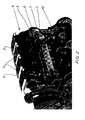
- FIG. 2 shows an alternative embodiment of an EGR control, in an exhaust flap 7 in the flow direction behind the exhaust gas removal 8 of the exhaust gas recirculation line 5 is arranged.
- the intake air passes via an intake passage 2 via not shown here Gas exchange valves in the individual combustion chambers 3 of the internal combustion engine 1.
- the intake pipe 2 adjacent is an exhaust pipe 4 provided, via which the exhaust gases from the combustion chambers. 3 are also removed via not shown gas exchange valves.
- the exhaust gas recirculation line 5 always remains connected to the intake passage 2 with its full passage cross-section. Is by closing the exhaust valve 7, the exhaust back pressure increases in the exhaust pipe 4, is correspondingly more Exhaust gas returned to the intake.
- thermocouple is preferably a bimetallic spring or a memory spring.
- Exhaust flap 7 may be known for engine braking devices exhaust flap be used.
- the internal combustion engine 1 is preferably a self-igniting internal combustion engine (Diesel engine), especially for use as stationary Motor, preferably for driving a generator for generating electricity.
- Diesel engine a self-igniting internal combustion engine
- the internal combustion engine is air-cooled and has an injection system on, which has a mechanical regulator for controlling the Injection has.
- Figure 3 shows an exhaust gas recirculation line 5 made of gray cast iron with a Inner 9 and outer ribbing 10 in plan view and longitudinal and cross section.
- the outer ribbing 10 is in this embodiment of itself in the radial direction of the exhaust gas recirculation line 5 extending and on the outer circumference circumferential rib rings 11.
- the individual Rib rings 11 are arranged one behind the other with the same distance.
- the inner ribbing 9 consists of one behind the other in the longitudinal direction arranged rib rings 12. These rib rings 12 are each from individual in the longitudinal direction and radially inward extending ribs 14. The size of these ribs 14, i. their Length in the longitudinal direction is the same for all ribs.
- the ribs 14a of a rib ring 12a offset to the ribs 14b of its adjacent rib ring 12b arranged. This offset is half the distance between two adjacent ribs 14 of a rib ring 12th
- Each rib ring 12 preferably consists of ten to twenty-two at the same distance on the inner circumference arranged ribs 14th In this preferred embodiment in FIG. 3, each one exists Rib ring 12 of sixteen at the same distance on the inner circumference arranged ribs 14th
- the reference numeral 13 denotes a connecting flange, which - as shown - as a screw or even for example can be designed as a plug-in flange.
Landscapes
- Engineering & Computer Science (AREA)
- Chemical & Material Sciences (AREA)
- Combustion & Propulsion (AREA)
- Mechanical Engineering (AREA)
- General Engineering & Computer Science (AREA)
- Physics & Mathematics (AREA)
- Fluid Mechanics (AREA)
- Analytical Chemistry (AREA)
- Exhaust-Gas Circulating Devices (AREA)
Abstract
Description
- Fig.1
- eine Ansicht einer Brennkraftmaschine mit einer AGR-Regelung, die eine Abgasklappe in der Abgasrückführleitung aufweist,
- Fig.2
- eine Ansicht einer Brennkraftmaschine mit einer AGR-Regelung, die eine Abgasklappe in der Abgasleitung aufweist und
- Fig.3
- eine Abgasrückführleitung aus Grauguss mit einer Innen- und Außenverrippung in Draufsicht und Längs- und Querschnitt.
- 1
- Brennkraftmaschine
- 2
- Ansaugleitung
- 3
- Brennräume
- 4
- Abgasleitung
- 5
- Abgasrückführleitung
- 6
- Thermoelement
- 7
- Abgasklappe
- 8
- Abgasentnahme
- 9
- Innenverrippung
- 10
- Außenverrippung
- 11
- außen umlaufender Rippenring
- 12, a, b
- Rippenring
- 13
- Anschlussflansch
- 14, a, b,
- Rippe
Claims (9)
- Brennkraftmaschine (1) mit einer Ansaugleitung (2) zur Zuführung der Ansaugluft zu den einzelnen Brennräumen (3), mit einer Abgasleitung (4) zur Abführung der Abgase aus den Brennräumen (3) und mit einer die Ansaugleitung (2) und die Abgasleitung (4) verbindenden Abgasrückführleitung (5), wobei in der Abgasleitung (4) ein die Rückführung von Abgas durch die Abgasrückführleitung (5) steuernder Temperatursensor angeordnet ist,
dadurch gekennzeichnet, dass der Temperatursensor ein mechanisches Thermoelement (6) ist, dessen temperaturabhängige Auslenkung eine Abgasklappe (7) mechanisch steuert. - Brennkraftmaschine nach Anspruch 1,
dadurch gekennzeichnet, dass das Thermoelement (6) in der Abgasleitung (4) in Strömungsrichtung vor der Abgasentnahme (8) der Abgasrückführleitung (5) angeordnet ist. - Brennkraftmaschine nach Anspruch 1 oder 2,
dadurch gekennzeichnet, dass die Abgasklappe (7) in der Abgasrückführleitung (5) angeordnet ist. - Brennkraftmaschine nach Anspruch 3,
dadurch gekennzeichnet, dass die Abgasklappe (7) in der Abgasrückführleitung (5) vor dem Eintritt in die Ansaugleitung (2) angeordnet ist. - Brennkraftmaschine nach Anspruch 1 oder 2,
dadurch gekennzeichnet, dass die Abgasklappe (7) in der Abgasleitung (4) in Strömungsrichtung hinter der Abgasentnahme (8) der Abgasrückführleitung (5) angeordnet ist. - Brennkraftmaschine nach einem der Ansprüche 1 bis 5,
dadurch gekennzeichnet, dass das Thermoelement (6) eine Bimetallfeder oder eine Memoryfeder ist. - Brennkraftmaschine nach einem der Ansprüche 1 bis 6,
dadurch gekennzeichnet, dass die Abgasklappe (7) eine für Motorbremsvorrichtungen bekannte Abgasklappe ist. - Brennkraftmaschine nach einem der Ansprüche 1 bis 7,
dadurch gekennzeichnet, dass die Brennkraftmaschine (1) eine selbstzündende Brennkraftmaschine ist. - Brennkraftmaschine nach einem der Ansprüche 1 bis 8 zur Verwendung als stationärer Motor, insbesondere zum Antrieb eines Generators zur Stromerzeugung.
Applications Claiming Priority (2)
| Application Number | Priority Date | Filing Date | Title |
|---|---|---|---|
| DE10360093 | 2003-12-20 | ||
| DE10360093A DE10360093A1 (de) | 2003-12-20 | 2003-12-20 | AGR-Regelung mit mechanischer Temperaturregelung |
Publications (2)
| Publication Number | Publication Date |
|---|---|
| EP1544450A2 true EP1544450A2 (de) | 2005-06-22 |
| EP1544450A3 EP1544450A3 (de) | 2007-08-22 |
Family
ID=34485542
Family Applications (1)
| Application Number | Title | Priority Date | Filing Date |
|---|---|---|---|
| EP04025856A Withdrawn EP1544450A3 (de) | 2003-12-20 | 2004-10-30 | Abgasrückführ-Regelung mit mechanischer Temperaturregelung |
Country Status (2)
| Country | Link |
|---|---|
| EP (1) | EP1544450A3 (de) |
| DE (1) | DE10360093A1 (de) |
Citations (9)
| Publication number | Priority date | Publication date | Assignee | Title |
|---|---|---|---|---|
| US3512509A (en) * | 1969-04-10 | 1970-05-19 | Atlantic Richfield Co | Control mechanism for exhaust recycle system |
| GB1423060A (en) * | 1972-04-29 | 1976-01-28 | Philips Nv | Device for converting calorific energy into mechanical energy |
| DE3931812C1 (de) * | 1989-09-23 | 1990-05-10 | Mercedes-Benz Aktiengesellschaft, 7000 Stuttgart, De | |
| US5056309A (en) * | 1987-07-03 | 1991-10-15 | Robert Bosch Gmbh | Internal combustion engine, particularly otto engine |
| JPH04136581A (ja) * | 1990-09-27 | 1992-05-11 | Mitsubishi Electric Corp | バルブ |
| EP0521411A1 (de) * | 1991-07-04 | 1993-01-07 | Dr.Ing.h.c. F. Porsche Aktiengesellschaft | Abgasleitung einer Brennkraftmaschine |
| DE19912317A1 (de) * | 1999-03-19 | 2000-09-28 | Daimler Chrysler Ag | Verfahren zur Regelung des Anteils der einer Brennkraftmaschine rückgeführten Abgasmenge |
| GB2353328A (en) * | 1999-08-20 | 2001-02-21 | Cummins Engine Co Inc | Turbocharged i.c. engine with EGR system and exhaust throttle |
| US20030127077A1 (en) * | 2002-01-10 | 2003-07-10 | Detroit Diesel Corporation | System for purging exhaust gases from exhaust gas recirculation system |
Family Cites Families (3)
| Publication number | Priority date | Publication date | Assignee | Title |
|---|---|---|---|---|
| DK170218B1 (da) * | 1993-06-04 | 1995-06-26 | Man B & W Diesel Gmbh | Stor trykladet dieselmotor |
| DE9421145U1 (de) * | 1994-04-28 | 1995-05-04 | Mtu Friedrichshafen Gmbh | Dieselbrennkraftmaschine mit in einer Abgasrückführleitung angeordnetem Wärmetauscher für die Abgaskühlung |
| DE19742445C1 (de) * | 1997-09-26 | 1998-11-19 | Daimler Benz Ag | Verfahren zur Regelung der Motorbremsleistung eines aufgeladenen Verbrennungsmotors |
-
2003
- 2003-12-20 DE DE10360093A patent/DE10360093A1/de not_active Withdrawn
-
2004
- 2004-10-30 EP EP04025856A patent/EP1544450A3/de not_active Withdrawn
Patent Citations (9)
| Publication number | Priority date | Publication date | Assignee | Title |
|---|---|---|---|---|
| US3512509A (en) * | 1969-04-10 | 1970-05-19 | Atlantic Richfield Co | Control mechanism for exhaust recycle system |
| GB1423060A (en) * | 1972-04-29 | 1976-01-28 | Philips Nv | Device for converting calorific energy into mechanical energy |
| US5056309A (en) * | 1987-07-03 | 1991-10-15 | Robert Bosch Gmbh | Internal combustion engine, particularly otto engine |
| DE3931812C1 (de) * | 1989-09-23 | 1990-05-10 | Mercedes-Benz Aktiengesellschaft, 7000 Stuttgart, De | |
| JPH04136581A (ja) * | 1990-09-27 | 1992-05-11 | Mitsubishi Electric Corp | バルブ |
| EP0521411A1 (de) * | 1991-07-04 | 1993-01-07 | Dr.Ing.h.c. F. Porsche Aktiengesellschaft | Abgasleitung einer Brennkraftmaschine |
| DE19912317A1 (de) * | 1999-03-19 | 2000-09-28 | Daimler Chrysler Ag | Verfahren zur Regelung des Anteils der einer Brennkraftmaschine rückgeführten Abgasmenge |
| GB2353328A (en) * | 1999-08-20 | 2001-02-21 | Cummins Engine Co Inc | Turbocharged i.c. engine with EGR system and exhaust throttle |
| US20030127077A1 (en) * | 2002-01-10 | 2003-07-10 | Detroit Diesel Corporation | System for purging exhaust gases from exhaust gas recirculation system |
Also Published As
| Publication number | Publication date |
|---|---|
| DE10360093A1 (de) | 2005-07-21 |
| EP1544450A3 (de) | 2007-08-22 |
Similar Documents
| Publication | Publication Date | Title |
|---|---|---|
| DE19750588B4 (de) | Vorrichtung zur Abgasrückführung für einen Verbrennungsmotor | |
| DE19633190B4 (de) | Kühlsystem für eine Brennkraftmaschine | |
| DE4328085C2 (de) | Rückführungsystem für Abgase | |
| DE102006024420A1 (de) | Regelungseinheit, Turboladersystem, Kraftfahrzeug mit einem Turboladersystem und Verfahren zum Regeln eines Turboladersystems | |
| DE202014102860U1 (de) | Kraftfahrzeug-Axialturbine mit Impulstrennung und Direkteinlass | |
| DE102014100739A1 (de) | Teilweise integrierter abgaskrümmer | |
| DE102010030094A1 (de) | Einlasssystem für Verbrennungsmsotor | |
| DE102015120497B4 (de) | Vorrichtung zum Herabkühlen einer Fahrzeugeinlasslufttemperatur und Verfahren, welches diese verwendet | |
| DE102017128180A1 (de) | Kondensatdispersionsanordnung | |
| DE102018120365A1 (de) | Durchführen einer diagnose an einem luftfilter mit einer elektrischen ladevorrichtung | |
| EP2256314A1 (de) | Verbrennungsmotor | |
| EP0908615B1 (de) | Abgasrückführventil | |
| DE102014113660A1 (de) | Fluidsteuerventilvorrichtung | |
| DE102014213042A1 (de) | System zur aktiven Konditionierung eines gasförmigen Ansaugfluids eines Verbrennungsmotors | |
| DE69914483T2 (de) | Abgasrückführungsventil und abgasrückführungsverfahren | |
| DE10360092A1 (de) | AGR-Kühler für insbesondere luftgekühlte Motoren | |
| DE102019216827A1 (de) | Ansaugsystem für ein Fahrzeug | |
| EP1544450A2 (de) | Abgasrückführ-Regelung mit mechanischer Temperaturregelung | |
| DE102012013249A1 (de) | Selbstzündende Brennkraftmaschine mit Einlassluft-Temperaturregelung und Verfahren zum Betreiben einer Brennkraftmaschine | |
| DE102022100076A1 (de) | Motoransaugkrümmer mit internen rippen | |
| EP2602468B1 (de) | Brennkraftmaschine mit Abgasrückführungseinrichtung | |
| DE102017204722B4 (de) | Abgasqualitätskontrolle | |
| DE102020208986A1 (de) | Brennkraftmaschine mit Niederdruck-Abgasrückführleitung, zwei Teilsträngen des Frischgasstrangs und Frischgas-Abgas-Wärmetauscher | |
| EP1058782B1 (de) | Ansaugvorrichtung für eine brennkraftmaschine | |
| DE112019001382T5 (de) | Steuergerät und steuerverfahren |
Legal Events
| Date | Code | Title | Description |
|---|---|---|---|
| PUAI | Public reference made under article 153(3) epc to a published international application that has entered the european phase |
Free format text: ORIGINAL CODE: 0009012 |
|
| AK | Designated contracting states |
Kind code of ref document: A2 Designated state(s): AT BE BG CH CY CZ DE DK EE ES FI FR GB GR HU IE IT LI LU MC NL PL PT RO SE SI SK TR |
|
| AX | Request for extension of the european patent |
Extension state: AL HR LT LV MK |
|
| PUAL | Search report despatched |
Free format text: ORIGINAL CODE: 0009013 |
|
| AK | Designated contracting states |
Kind code of ref document: A3 Designated state(s): AT BE BG CH CY CZ DE DK EE ES FI FR GB GR HU IE IT LI LU MC NL PL PT RO SE SI SK TR |
|
| AX | Request for extension of the european patent |
Extension state: AL HR LT LV MK |
|
| AKX | Designation fees paid | ||
| STAA | Information on the status of an ep patent application or granted ep patent |
Free format text: STATUS: THE APPLICATION IS DEEMED TO BE WITHDRAWN |
|
| 18D | Application deemed to be withdrawn |
Effective date: 20080223 |
|
| REG | Reference to a national code |
Ref country code: DE Ref legal event code: 8566 |