EP0521320B1 - Schutzhelm mit verbesserter akustischer Wirkung - Google Patents
Schutzhelm mit verbesserter akustischer Wirkung Download PDFInfo
- Publication number
- EP0521320B1 EP0521320B1 EP92109800A EP92109800A EP0521320B1 EP 0521320 B1 EP0521320 B1 EP 0521320B1 EP 92109800 A EP92109800 A EP 92109800A EP 92109800 A EP92109800 A EP 92109800A EP 0521320 B1 EP0521320 B1 EP 0521320B1
- Authority
- EP
- European Patent Office
- Prior art keywords
- helmet
- sound
- helmet according
- bow
- protective helmet
- Prior art date
- Legal status (The legal status is an assumption and is not a legal conclusion. Google has not performed a legal analysis and makes no representation as to the accuracy of the status listed.)
- Expired - Lifetime
Links
- 230000001681 protective effect Effects 0.000 title claims description 31
- 239000002775 capsule Substances 0.000 claims description 20
- 230000008878 coupling Effects 0.000 claims description 12
- 238000010168 coupling process Methods 0.000 claims description 12
- 238000005859 coupling reaction Methods 0.000 claims description 12
- 230000000063 preceeding effect Effects 0.000 claims 4
- 238000007373 indentation Methods 0.000 claims 1
- 210000005069 ears Anatomy 0.000 description 5
- 210000003128 head Anatomy 0.000 description 4
- 238000009413 insulation Methods 0.000 description 4
- 230000005540 biological transmission Effects 0.000 description 3
- 241000269400 Sirenidae Species 0.000 description 2
- 230000000694 effects Effects 0.000 description 2
- 239000004033 plastic Substances 0.000 description 2
- 238000004804 winding Methods 0.000 description 2
- 239000004793 Polystyrene Substances 0.000 description 1
- 229910000831 Steel Inorganic materials 0.000 description 1
- 238000004026 adhesive bonding Methods 0.000 description 1
- 230000002238 attenuated effect Effects 0.000 description 1
- 244000052616 bacterial pathogen Species 0.000 description 1
- 230000001413 cellular effect Effects 0.000 description 1
- 238000010276 construction Methods 0.000 description 1
- 238000013016 damping Methods 0.000 description 1
- 239000006260 foam Substances 0.000 description 1
- 210000001061 forehead Anatomy 0.000 description 1
- 238000009434 installation Methods 0.000 description 1
- 238000000034 method Methods 0.000 description 1
- 229920002223 polystyrene Polymers 0.000 description 1
- 238000001228 spectrum Methods 0.000 description 1
- 239000010959 steel Substances 0.000 description 1
- XLYOFNOQVPJJNP-UHFFFAOYSA-N water Substances O XLYOFNOQVPJJNP-UHFFFAOYSA-N 0.000 description 1
- 238000003466 welding Methods 0.000 description 1
Images


Classifications
-
- A—HUMAN NECESSITIES
- A42—HEADWEAR
- A42B—HATS; HEAD COVERINGS
- A42B3/00—Helmets; Helmet covers ; Other protective head coverings
- A42B3/04—Parts, details or accessories of helmets
- A42B3/16—Ear protection devices
- A42B3/166—Integral hearing protection
-
- A—HUMAN NECESSITIES
- A42—HEADWEAR
- A42B—HATS; HEAD COVERINGS
- A42B3/00—Helmets; Helmet covers ; Other protective head coverings
- A42B3/04—Parts, details or accessories of helmets
- A42B3/18—Face protection devices
- A42B3/22—Visors
- A42B3/221—Attaching visors to helmet shells, e.g. on motorcycle helmets
- A42B3/222—Attaching visors to helmet shells, e.g. on motorcycle helmets in an articulated manner, e.g. hinge devices
-
- A—HUMAN NECESSITIES
- A42—HEADWEAR
- A42B—HATS; HEAD COVERINGS
- A42B3/00—Helmets; Helmet covers ; Other protective head coverings
- A42B3/04—Parts, details or accessories of helmets
- A42B3/30—Mounting radio sets or communication systems
Definitions
- the invention relates to a shelter, in particular a motorcycle helmet, according to the preamble of claim 1.
- the outer shell covers the ear area; in the so-called full-face helmets, an integral strap (chin strap) is additionally led around the chin area of the helmet wearer.
- chin strap a hinged, transparent visor.
- the soundproofing behavior of the known homes is unfavorable, since higher frequencies, which contain important acoustic information serving for traffic safety, such as howling sirens, horn sounds, etc., are strongly attenuated by the protective helmet, whereas low frequencies are passed almost unhindered to the ear of the helmet wearer.
- the main spectrum of wind noise from the headwind is in this low-frequency range, especially for motorcyclists.
- openings are arranged near the ears in the protective helmet, the high frequencies and thus the acoustic warning and information content of the surroundings can reach the motorcycle rider unhindered.
- openings must be designed so as to be closable in order to avoid being masked by wind noise at higher driving speeds (from 50 to 60 km / h) outside city traffic.
- a protective helmet in particular for forestry workers, is known from CH-A-666 389.
- the helmet shell of the well-known protective helmet extends over the forehead, both ears, the back of the head and the neck of the helmet wearer.
- Each listening hole has a listening hole in the area of each ear.
- Each listening hole can be quickly closed and released again by means of a slide mounted in a recess in the helmet shell.
- the helmet also protects the particularly vulnerable temples and neck areas of the head. It ensures a secure hold on the head and quick and easy closing and opening of the listening holes.
- a protective helmet for white water riders is also known from DE-U-80 07 318.
- This protective helmet has an opening in the ear area, which can be opened or closed either by means of a movably arranged closure part.
- the present invention has for its object to develop a helmet according to the preamble of claim 1 such that maximum acoustic insulation at high speeds and this insulation can be removed at low speeds, the construction should be simple and inexpensive.
- the invention there is the advantage that there are sound passage openings in the protective helmet lying opposite the cavum conchae (auditory canal) of the helmet wearer, in particular at low speeds, such as when driving through closed towns, the possibility of sound effects of higher noise frequencies the important safety signals serving to ensure safe driving, to be able to lead to the ear unhindered, but at high speeds to keep the sound effects caused by wind noise away from the ear by closing the sound passage openings provided in the protective helmet.
- a cost-effective solution with excellent acoustic insulation is achieved which, on the other hand, enables acoustic signals to be received by arranging an opening in the soundproofing capsule.
- the opening has an area of 10 to 20 cm2 in order to let sound information through in the usual frequency range, and is preferably aligned with the approximately equally large sound passage opening in the shell.
- Sound insulation at high speeds is achieved by covering the opening in the noise protection capsule.
- the sound passage opening in the helmet shell can also be covered, the opening and the sound passage opening expediently being covered together by flat, displaceably mounted, interconnected but acoustically decoupled plates.
- the soundproofing capsule can be inserted and fastened in a correspondingly shaped recess in the padding.
- the soundproofing capsules lie in the recess of the padding and are glued there, for example, without coming into contact with the helmet shell.
- An additional holder can be achieved in that the two soundproofing capsules arranged on the sides of the upholstery can be connected by means of a support bracket arranged on the upholstery or the helmet shell, with this development also providing acoustic decoupling from the shell.
- the protective helmet expediently has a foldable visor to keep the wind away.
- some motorcyclists prefer protective helmets without a visor and without a chin guard with an indicated parasol, the invention with the configurations set out in subclaims 2 to 7 also being applicable to these helmets.
- the sound passage openings and the openings can be covered by pivoting the visor.
- a comfortable opening and closing of the two sound transmission openings in connection with the visor is achieved, which is usually anyway at slow speeds is left open, in which case the openings are also open and sound information such as horns and sirens or engine noises can reach the ears.
- the sound passage openings and the openings can be covered independently of the position of the visor together via a coupling device by actuating an adjustment device attached to the helmet.
- the adjusting device has a cable, the two ends of which are connected to cover flaps which are pivotally attached to the helmet above the sound passage openings and over the sound passage openings, that the cable pull is connected in the region between its ends to a manually operated rotary knob attached to the outside of the helmet , and that a spring connected to the helmet is arranged on both cover plates, which exerts a tensile force on the cable.
- the cable pull is connected in the area between its ends to an adjusting slide which is attached to the outside of the helmet and can be moved and locked manually in the cable pulling direction, and that a spring connected to the helmet is arranged on each cover plate, which pulls a pulling force on the cable pull exercises.
- the position of the rotary knob or adjustment slide is conveniently provided on the front of the chin guard, but also on the side of the helmet.
- the cover plates are pulled forward by the pull rope by turning the rotary knob and the resulting winding of the cable around the shaft of the rotary knob release the two sound passage openings, the cable being held taut by the springs attached to the other side of the cover plates.
- the springs pull the cover plates in the closed position when the rotary knob is turned in reverse and the cable is unwound.
- an adjustment slide which is displaceable and lockable in the cable direction is provided, which moves the cable back and forth in the direction of the cover plates without changing the length of the cable, a tension spring on the cover plates each holding the cable pull tight.
- the cover plates are attached so that one is pivoted to the front of the helmet in the open position and the other to the rear of the helmet.
- the protective helmet has a pivotable bracket arranged around the visor, the pivot axes of the visor and the bracket being arranged coaxially. It is advantageous that the sound passage openings and the openings can be at least partially covered and disclosed by pivoting the bracket. It is expediently provided that the visor has at least one lateral stop which can be brought into engagement with the bracket for opening the visor.
- the bracket covers the sound passage opening in the helmet shell or reveals it by swiveling through an angular range in cooperation with a coupling device. This ensures that when the visor is closed, the two sound transmission openings in the helmet shell and in the soundproofing capsule can be at least partially opened if this is necessary in certain traffic situations.
- the coupling device advantageously each has a lever which is pivotally attached to the side of the bracket and which can be pivoted rearward about its pivot point and whose forward pivoting movement is limited by a stop.
- the lever has an elongated hole at its free end which engages with a cam which is mounted on a cover plate which passes over the sound passage openings, which is pivotably mounted on the protective helmet and is connected to one end of a tension spring which is connected at its other end is attached to the hard hat.
- the bracket In the closed position of the cover plates, the bracket is in its lower position.
- the tension spring exerts a pull on the lever in such a way that it is pulled against the stop.
- the bracket and visor are expediently coupled by an elongated hole in the visor and a cam arranged therein and connected to the bracket, so that the bracket is moved a little before it takes the visor over the cam.
- the elongated hole has the shape of an arc segment with the center of rotation of the bracket and visor.
- the coupling device is alternatively advantageously designed such that the bracket is toothed on each side Has a circular segment, the center of which is equal to the pivot point of the bracket, and that the cover plates are designed as pivotable toothed circle segments which are in engagement with the toothed circular segments of the bracket in such a way that when the bracket is moved upward, the cover plates release the sound passage openings.
- a coupling of the actuation of the plates to cover the openings with the visor movement or the bow movement is not desired, a commercially available visor in the area of the ears can be reduced, so that manual actuation of the outer plate is possible, which can be carried out for this purpose with a profiled surface is.
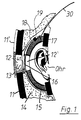
- a protective helmet 10 has an outer shell 11, in which a circular sound passage opening 12 is made in the ear area.
- the sound passage opening 12 is covered with a somewhat larger plate 13, which is displaceable in a guide 11 'formed on the shell 11, the guide 11' being in the form of an elongated hole, so that the plate 13 is displaceable upwards to open the sound passage opening 12 is what the guide is dimensioned so that the plate 13 is clamped in the upper position.
- the plate 13 can have a profiling on the outward-facing surface for better handling.
- the plates 13 are independent of one another and can be displaced from the position of a visor 20 which can be folded about a pivot point M.
- FIG. 1 shows a section along the line I - I in FIG. 2 through a soundproof capsule 15 which is molded into a helmet inner padding 14 and has a circumferential padding 17 on its edge facing the head of the helmet wearer.
- an opening 12 ' is made in the soundproofing capsule 15, which opening is approximately circular and is shown covered with a plate 16, the plate 16 also being approximately circular with a slightly larger diameter than the opening 12'. is executed.
- the tongue 18 is expediently made of steel and is curved in such a way that it presses the plate 16 resiliently onto the openings 12 'and, when opened, holds the plate 16 on the surface of the soundproofing capsule 15, the tongue 18 pushing upwards through the clamp 19, for which a corresponding recess is provided in the padding 14.
- the width of the tongue 18 and the dimensioning of the bracket 19 are such that the tongue 18 does not tilt when it is moved.
- the plate 13 carries a web 40 on its inwardly facing surface.
- the plate 16 carries an annular body 41 on its outwardly facing surface, the central recess of which engages with the free end of the web 40 when the plates 13, 16 are displaced.
- the body 41 is preferably made of a cellular plastic, for example polystyrene, and is glued on, as a result of which good acoustic damping is achieved with the contact surface of the parts 40, 41 which is only small in any case is, which can be improved by a rubber mounting of the touching parts 40, 41.
- the plates 13, 16 and the web 40 are expediently made of plastic, the assembly being carried out by gluing or welding during installation in the helmet 10. In the shown closed position of the opening 12 and the opening 12 ', the web 40 forms a stop at the lower edge of the opening 12 and in the open position a stop at the upper edge.
- the web 40 is arranged further to the center of the plate 13, 16 and does not act as a stop, this taking place through the visor 20 on the shell 11.
- a carrying bracket 30 In the upper area of the soundproofing capsule 15, one end of a carrying bracket 30 is e.g. attached in foam; the support bracket 30 lies loosely on the inside on the padding 14 and leads in a corresponding design to the opposite soundproofing capsule. If necessary, a holding clip (not shown) can be provided on the padding 14 for the support bracket 30 in the upper region.
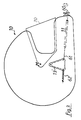
- another embodiment of the protective helmet 10 has a cover flap 13 'which is pivotable in the ear area around a pivot point attached in its upper area and which has the shape of a triangle with rounded corners and, in the position shown, covers a sound passage opening in the helmet shell 11 , wherein the sound passage opening is dimensioned somewhat smaller and shown in dashed lines with the same shape.
- a knob 60 is attached to the front of the chin guard of the helmet 10 and has an area to which a traction cable 61 is fastened approximately in its central area. The two free ends of the pull cable 61 are each attached to the side region of the cover flap 13 'facing them.
- the cover flap 13 ' On the other side area of the cover flap 13 'is on each helmet side with the attached one end of a tension spring 62, which is attached with its other end to the helmet shell 11 so that the two tension springs 62 pull the tension cable 61 taut.
- the traction rope 61 is partially guided through channels (shown in dashed lines) on the helmet shell 11. If the rotary knob 60 (see arrow) is rotated, the pull rope 61 winds around the rotary knob 60 and shortens, as a result of which the cover flaps 13 'are pivoted forward against the spring force of the tension springs 62 away from the sound passage openings and release them. Upon reverse rotation of the rotary knob 60, the tension springs 62 pull the cover flaps 13 ′ back into the closed position.
- FIG. 4 shows yet another embodiment of a protective helmet 10, which differs from the embodiment shown in FIG. 3 in that the pull rope 61 is not shortened by winding, but does not change its effective length.
- the cover flaps 13 ' are actuated in such a way that the pull cable 61 is fastened at a selectable point between its free ends, which are fastened to the facing sides of the cover flaps 13', on a slide 60 'which clamps on a guide track attached to the chin guard of the protective helmet 10 or can be locked.
- Tension springs 62 are attached to the other sides of the cover flaps 13 'and hold the tension cable 61 taut.
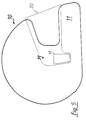
- FIG. 5 shows a further embodiment of a helmet 10 with a helmet shell 11, in which the visor 20, which can be pivoted about a point M, is pulled down in the ear area so that it covers the sound transmission openings 12 in the closed position. If the visor 20 is pivoted upward about the point M, the sound passage openings 12 are successively exposed.
- the covering of the sound passage openings 12 is coupled to the opening 12 'in the soundproofing capsule 15 (not visible in FIG. 5) in such a way that a web 40 projecting inward from the visor 20 (see FIG. 1) Pushes plate 16 away during the visor movement.
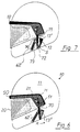
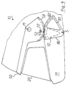
- FIGS. 6, 7 and 8 show yet another embodiment of a protective helmet 10 with a helmet shell 11, a visor 20 and a generally U-shaped bracket 50 attached under the visor 20 around a common one
- the pivot point M can be pivoted, the bracket 50 being shaped downward in the area of the pivot point M and projecting above the visor 20 at the front on the helmet shell 11.
- the movements of the visor 20 with the bracket 50 are coupled to one another in such a way that the visor 20 has an elongated hole 21 which is arranged in the shape of a arc of a circle around the pivot point M, and that the bracket 50 has a downward-facing section on the areas formed downward, with an offset through the elongated hole 21 has arm 51.
- the bracket 50 When the bracket 50 is lifted by gripping the area projecting from the front of the visor 20, the offset of the arm 51 is moved through the elongated hole 21 until the offset lies at the end of the elongated hole 21, and when the bracket 50 is moved further, the visor 20 is carried along and after open at the top.
- a hinge 71 is attached, on which a lever 70 is pivotally attached, which has an elongated hole 72 at its free end.
- the hinge 71 is shaped such that the lever 70 can only be pivoted from the position shown in FIG. 6 in the direction of the arrow R and back into the starting position.
- cover plates 13 ′′ are each pivotably arranged around a point S in the ear area, the cover plates 13 ′′ being generally circular in section with the tip pointing downward and carrying the pivot point S.
- the cover plates 13 ′′ sweep through sound passage openings 12.
- the cover plates 13 ′′ carry on their outward-facing surface on their forward-facing edge a cam 73 which is slidably guided in the elongated hole 72.
- a tension spring 62 ′ is also attached, the other end of which is attached to the helmet shell 11.
- bracket 50 is slightly raised, the visor 20 does not yet engage the bracket 50 and remains closed.
- the movement of the arm 51 also moves the lever 70 against the direction of the arrow R and the cover plate 13 ′′ is partially opened by the tension spring 62 ′.
- the visor 20 is also opened, since the cranking of the arm 51 engages with the wall of the elongated hole 21, and the tension spring 62 'pivots the cover plate 13' 'into the open position, wherein the hinge 71 pivots in the direction of the arrow R and the cam 73 bears against the outer end of the elongated hole 72.
- the lever 70, the cover plate 13 ′′ and the spring 62 ′ are shown on the outside of the helmet shell; alternatively, the parts mentioned can also be arranged concealed beneath the helmet shell.
- FIG. 9 shows yet another embodiment of a protective helmet 10 with a helmet shell 11 and a closed visor 20, which is arranged below a generally U-shaped bracket 50, which has the front Visor 20 protrudes above and below a common pivot point M each has a circular sector-shaped, downward extension, which has a toothing 53.
- An arc-shaped elongated hole 52 is formed on the extension of the bracket 50 between the pivot point M and the toothing 53.
- the visor 20 has a cam 22 on each side, which is in engagement with the elongated hole 52.
- a cover plate 80 is pivotally arranged on the helmet shell 11 laterally below the pivot point M about a pivot point S.
- the cover plate 80 is generally in the form of a circular sector, the pivot point S being arranged at the tip of the circular sector and the opposite circular arc-shaped edge having a toothing 82 which meshes with the toothing 53.
- a generally circular sector-shaped opening 81 is made, which has approximately the shape of the sound passage opening 12 in the helmet shell.
- the meshing toothing 82 is carried along by the toothing 53, so that the cover plate 80 rotates counterclockwise (with reference to FIG. 9), and the sound passage opening 12 and the opening 81 successively come to cover.
- the cover plate 13 ′′ (FIGS. 6, 7, 8) and the cover plate 80 (FIG. 9) can each be connected to a plate 16 on a soundproofing capsule 15 analogously to the embodiment shown in FIGS. 1 and 2, the guide for the plate 16 correspondingly the train one Web 40 is designed.
Landscapes
- Health & Medical Sciences (AREA)
- General Health & Medical Sciences (AREA)
- Otolaryngology (AREA)
- Physics & Mathematics (AREA)
- Acoustics & Sound (AREA)
- Helmets And Other Head Coverings (AREA)
Applications Claiming Priority (2)
| Application Number | Priority Date | Filing Date | Title |
|---|---|---|---|
| DE4119906 | 1991-06-17 | ||
| DE4119906A DE4119906C1 (enExample) | 1991-06-17 | 1991-06-17 |
Publications (2)
| Publication Number | Publication Date |
|---|---|
| EP0521320A1 EP0521320A1 (de) | 1993-01-07 |
| EP0521320B1 true EP0521320B1 (de) | 1995-01-04 |
Family
ID=6434112
Family Applications (1)
| Application Number | Title | Priority Date | Filing Date |
|---|---|---|---|
| EP92109800A Expired - Lifetime EP0521320B1 (de) | 1991-06-17 | 1992-06-11 | Schutzhelm mit verbesserter akustischer Wirkung |
Country Status (2)
| Country | Link |
|---|---|
| EP (1) | EP0521320B1 (enExample) |
| DE (2) | DE4119906C1 (enExample) |
Families Citing this family (2)
| Publication number | Priority date | Publication date | Assignee | Title |
|---|---|---|---|---|
| IT1271848B (it) * | 1994-02-03 | 1997-06-09 | Franco Malenotti | Casco per motociclisti, con sistema perfezionato a incastro della visiera, sistema di bloccaggio di sicurezza della visiera, sistema perfezionato di ventilazione interna, e protezione interna estraibile e lavabile |
| IT201800009613A1 (it) * | 2018-10-19 | 2020-04-19 | Momo Design Srl | Casco di protezione |
Family Cites Families (12)
| Publication number | Priority date | Publication date | Assignee | Title |
|---|---|---|---|---|
| GB1047237A (enExample) * | ||||
| US2340872A (en) * | 1942-05-13 | 1944-02-08 | Flynn Thomas Joseph | Helmet |
| US3190973A (en) * | 1960-05-13 | 1965-06-22 | Leonard P Frieder | Rigid shell helmet and rigging and sound attenuating means therefor |
| US3178723A (en) * | 1963-05-24 | 1965-04-20 | Leonard P Frieder | Sound attenuating device and supporting means in a helmet |
| FR1446416A (fr) * | 1965-06-09 | 1966-07-22 | Optique Scient L | Casque de pilote d'avion avec mécanisme de manoeuvre et de verrouillage de l'écrande protection |
| US4114197A (en) * | 1976-09-09 | 1978-09-19 | Morton William G | Inter-liner for a safety helmet and method of assembly |
| IT1207216B (it) * | 1979-07-27 | 1989-05-17 | Nava Pier Luigi | Dispositivo per azionare visiere di caschi, particolarmente per motociclisti. |
| DE8007318U1 (de) * | 1980-03-18 | 1980-06-26 | Hans Roemer Gmbh + Co, 7910 Neu-Ulm | Schutzhelm für Wildwasserfahrer und Wassersportler |
| CH666389A5 (en) * | 1985-04-19 | 1988-07-29 | Forstwirtschaftliche Zentralst | Safety helmet for forestry workers - consists of casing over both ears with hearing holes covered by slide pieces |
| DE8534132U1 (de) * | 1985-12-04 | 1986-06-26 | Witzmann, Josef, 8400 Regensburg | Integral-Schutzhelm mit einziehbarem Visier |
| DD253760A1 (de) * | 1986-11-21 | 1988-02-03 | Perfekt Veb | Schutzhelm mit beluefteter visierinnenseite |
| FR2610484A1 (fr) * | 1987-02-09 | 1988-08-12 | Degoin Emmanuel | Systeme d'ouverture et de fermeture par telecommande de l'ecran d'un casque pour motocycliste |
-
1991
- 1991-06-17 DE DE4119906A patent/DE4119906C1/de not_active Expired - Lifetime
-
1992
- 1992-06-11 EP EP92109800A patent/EP0521320B1/de not_active Expired - Lifetime
- 1992-06-11 DE DE59201126T patent/DE59201126D1/de not_active Expired - Fee Related
Also Published As
| Publication number | Publication date |
|---|---|
| DE59201126D1 (de) | 1995-02-16 |
| EP0521320A1 (de) | 1993-01-07 |
| DE4119906C1 (enExample) | 1992-07-23 |
Similar Documents
| Publication | Publication Date | Title |
|---|---|---|
| DE69414579T2 (de) | Vorrichtung für mobiltelefone | |
| DE2921434C2 (de) | Hörsprechgarnitur zur Verwendung an einem Schutzhelm | |
| DE69415434T2 (de) | Helm | |
| DE1541256A1 (de) | Schalldaempfungsvorrichtung | |
| DE2656400A1 (de) | Schutzhelm | |
| DE2156338A1 (de) | Schutzende Kopfbedeckung | |
| DE1938259A1 (de) | Ohrenschuetzer mit frequenzabhaengiger Charakteristik | |
| WO2004000054A2 (de) | Helm | |
| EP0521320B1 (de) | Schutzhelm mit verbesserter akustischer Wirkung | |
| WO2021048281A9 (de) | Visiermechanik für einen schutzhelm | |
| WO2006136519A1 (de) | Schutzhelm | |
| EP2422636A2 (de) | Schutzhelm | |
| DE29800973U1 (de) | Helm, insbesondere Motorradhelm | |
| DE102004048842B3 (de) | Schutzhelm | |
| DE3316920C1 (de) | Sturzhelm mit einer Einrichtung zur Belüftung des Helminnenraums | |
| DE102010011860B4 (de) | Vorrichtung zur Kontrolle des Jagd- und/oder Fluchtverhaltens von domestizierten Tieren | |
| EP1312274B1 (de) | Motorrad-Integralhelm | |
| DE1762371A1 (de) | Kopfhoerer | |
| US5027479A (en) | Adjustable chin strap for motorcycle helmets | |
| EP0248003A1 (de) | Schutzhelm für motorradfahrer, rennsportler oder dergleichen | |
| DE60102678T2 (de) | Integralhelm | |
| EP1008477A2 (de) | Ausstellbares Dachteil eines Fahrzeuges | |
| EP2057910A2 (de) | Schutzhelmsystem | |
| DE10057814A1 (de) | Vorrichtung zur Halterung eines Helms | |
| DE912921C (de) | Ohrenschuetzer |
Legal Events
| Date | Code | Title | Description |
|---|---|---|---|
| PUAI | Public reference made under article 153(3) epc to a published international application that has entered the european phase |
Free format text: ORIGINAL CODE: 0009012 |
|
| AK | Designated contracting states |
Kind code of ref document: A1 Designated state(s): DE ES FR GB IT |
|
| 17P | Request for examination filed |
Effective date: 19930226 |
|
| 17Q | First examination report despatched |
Effective date: 19940610 |
|
| GRAA | (expected) grant |
Free format text: ORIGINAL CODE: 0009210 |
|
| AK | Designated contracting states |
Kind code of ref document: B1 Designated state(s): DE ES FR GB IT |
|
| PG25 | Lapsed in a contracting state [announced via postgrant information from national office to epo] |
Ref country code: GB Effective date: 19950104 Ref country code: FR Effective date: 19950104 Ref country code: ES Free format text: THE PATENT HAS BEEN ANNULLED BY A DECISION OF A NATIONAL AUTHORITY Effective date: 19950104 Ref country code: IT Free format text: LAPSE BECAUSE OF FAILURE TO SUBMIT A TRANSLATION OF THE DESCRIPTION OR TO PAY THE FEE WITHIN THE PRESCRIBED TIME-LIMIT;WARNING: LAPSES OF ITALIAN PATENTS WITH EFFECTIVE DATE BEFORE 2007 MAY HAVE OCCURRED AT ANY TIME BEFORE 2007. THE CORRECT EFFECTIVE DATE MAY BE DIFFERENT FROM THE ONE RECORDED. Effective date: 19950104 |
|
| REF | Corresponds to: |
Ref document number: 59201126 Country of ref document: DE Date of ref document: 19950216 |
|
| RAP4 | Party data changed (patent owner data changed or rights of a patent transferred) |
Owner name: HUETTENBRINK, KARL BERND, DR. Owner name: PILTZ, HENRICH Owner name: LINDEMANN, JUERGEN, DR. |
|
| EN | Fr: translation not filed | ||
| GBV | Gb: ep patent (uk) treated as always having been void in accordance with gb section 77(7)/1977 [no translation filed] |
Effective date: 19950104 |
|
| PLBE | No opposition filed within time limit |
Free format text: ORIGINAL CODE: 0009261 |
|
| STAA | Information on the status of an ep patent application or granted ep patent |
Free format text: STATUS: NO OPPOSITION FILED WITHIN TIME LIMIT |
|
| 26N | No opposition filed | ||
| PGFP | Annual fee paid to national office [announced via postgrant information from national office to epo] |
Ref country code: DE Payment date: 19980629 Year of fee payment: 7 |
|
| PG25 | Lapsed in a contracting state [announced via postgrant information from national office to epo] |
Ref country code: DE Free format text: LAPSE BECAUSE OF NON-PAYMENT OF DUE FEES Effective date: 19990630 |