EP0520944B1 - Procédé et dispositif pour enlever des articles plats arrivant en formation imbriquée, en particulier des produits imprimés - Google Patents
Procédé et dispositif pour enlever des articles plats arrivant en formation imbriquée, en particulier des produits imprimés Download PDFInfo
- Publication number
- EP0520944B1 EP0520944B1 EP92810456A EP92810456A EP0520944B1 EP 0520944 B1 EP0520944 B1 EP 0520944B1 EP 92810456 A EP92810456 A EP 92810456A EP 92810456 A EP92810456 A EP 92810456A EP 0520944 B1 EP0520944 B1 EP 0520944B1
- Authority
- EP
- European Patent Office
- Prior art keywords
- belt conveyor
- printed products
- conveying
- products
- over
- Prior art date
- Legal status (The legal status is an assumption and is not a legal conclusion. Google has not performed a legal analysis and makes no representation as to the accuracy of the status listed.)
- Expired - Lifetime
Links
Images

Classifications
-
- B—PERFORMING OPERATIONS; TRANSPORTING
- B65—CONVEYING; PACKING; STORING; HANDLING THIN OR FILAMENTARY MATERIAL
- B65H—HANDLING THIN OR FILAMENTARY MATERIAL, e.g. SHEETS, WEBS, CABLES
- B65H29/00—Delivering or advancing articles from machines; Advancing articles to or into piles
- B65H29/66—Advancing articles in overlapping streams
- B65H29/669—Advancing articles in overlapping streams ending an overlapping stream
-
- B—PERFORMING OPERATIONS; TRANSPORTING
- B65—CONVEYING; PACKING; STORING; HANDLING THIN OR FILAMENTARY MATERIAL
- B65H—HANDLING THIN OR FILAMENTARY MATERIAL, e.g. SHEETS, WEBS, CABLES
- B65H29/00—Delivering or advancing articles from machines; Advancing articles to or into piles
- B65H29/66—Advancing articles in overlapping streams
- B65H29/6654—Advancing articles in overlapping streams changing the overlapping figure
- B65H29/6663—Advancing articles in overlapping streams changing the overlapping figure reversing the overlapping figure
-
- B—PERFORMING OPERATIONS; TRANSPORTING
- B65—CONVEYING; PACKING; STORING; HANDLING THIN OR FILAMENTARY MATERIAL
- B65H—HANDLING THIN OR FILAMENTARY MATERIAL, e.g. SHEETS, WEBS, CABLES
- B65H2301/00—Handling processes for sheets or webs
- B65H2301/10—Selective handling processes
-
- B—PERFORMING OPERATIONS; TRANSPORTING
- B65—CONVEYING; PACKING; STORING; HANDLING THIN OR FILAMENTARY MATERIAL
- B65H—HANDLING THIN OR FILAMENTARY MATERIAL, e.g. SHEETS, WEBS, CABLES
- B65H2301/00—Handling processes for sheets or webs
- B65H2301/40—Type of handling process
- B65H2301/43—Gathering; Associating; Assembling
- B65H2301/435—Gathering; Associating; Assembling on collecting conveyor
- B65H2301/4354—Gathering; Associating; Assembling on collecting conveyor with grippers
-
- B—PERFORMING OPERATIONS; TRANSPORTING
- B65—CONVEYING; PACKING; STORING; HANDLING THIN OR FILAMENTARY MATERIAL
- B65H—HANDLING THIN OR FILAMENTARY MATERIAL, e.g. SHEETS, WEBS, CABLES
- B65H2301/00—Handling processes for sheets or webs
- B65H2301/40—Type of handling process
- B65H2301/44—Moving, forwarding, guiding material
- B65H2301/447—Moving, forwarding, guiding material transferring material between transport devices
- B65H2301/4471—Grippers, e.g. moved in paths enclosing an area
- B65H2301/44712—Grippers, e.g. moved in paths enclosing an area carried by chains or bands
-
- B—PERFORMING OPERATIONS; TRANSPORTING
- B65—CONVEYING; PACKING; STORING; HANDLING THIN OR FILAMENTARY MATERIAL
- B65H—HANDLING THIN OR FILAMENTARY MATERIAL, e.g. SHEETS, WEBS, CABLES
- B65H2301/00—Handling processes for sheets or webs
- B65H2301/40—Type of handling process
- B65H2301/44—Moving, forwarding, guiding material
- B65H2301/447—Moving, forwarding, guiding material transferring material between transport devices
- B65H2301/4473—Belts, endless moving elements on which the material is in surface contact
- B65H2301/44732—Belts, endless moving elements on which the material is in surface contact transporting articles in overlapping stream
-
- B—PERFORMING OPERATIONS; TRANSPORTING
- B65—CONVEYING; PACKING; STORING; HANDLING THIN OR FILAMENTARY MATERIAL
- B65H—HANDLING THIN OR FILAMENTARY MATERIAL, e.g. SHEETS, WEBS, CABLES
- B65H2511/00—Dimensions; Position; Numbers; Identification; Occurrences
- B65H2511/20—Location in space
- B65H2511/22—Distance
Definitions
- the present invention is in the field of further processing of printed products. It relates to a method and a device according to the preambles of the corresponding independent patent claims and is used for conveying away flat products, in particular multi-leaf, folded printed products which are arranged in a scale formation at a certain distance one behind the other and are fed overlapping one another like roof tiles, with the aid of a conveying means, that each holds a printed product or a group of printed products.
- Printed products are designed as a stream of shingles, for example, from rotary machines or from corresponding intermediate stores, for example winding.
- it is advantageous to further convey such shingled streams in another form for example as a conveying stream in which each printed product or a certain number of printed products is transported by a gripper, a pulling element moving a number of such grippers.
- a conveying stream in which each printed product or a certain number of printed products is transported by a gripper, a pulling element moving a number of such grippers.
- a forced formation is created in which the relative position of the printed products to each other is rigidly determined by the grippers or similar conveying tools.
- the shingled stream is guided on a feed belt conveyor into a corresponding takeover area, in which the printed products are gripped by the grippers.
- the methods described preferably provide for a deflection of the stream of shingles by approximately 180 ° upwards or downwards before the actual takeover, a change in position such that each product of the stream of sheds in each case rests on the follow-up product or on the follow-up products and so the front edges of the printed products in the conveying direction lie on the support side (underside) of the shingled stream.
- embodiments are also described in the cited documents which are used to convey away shingled streams with leading edges lying at the top.
- Unevenness in the intervals of the printed products of a shingled stream can damage the devices described Guide printed products, for example, through the grippers, so that it is advantageous not only to adjust the lateral alignment of the printed products, but also their distances in the transport direction prior to the takeover or to correct them during the takeover.
- means are described, for example, with which products that are fed in too small a distance are stopped immediately before the takeover and are clocked in correctly, while products that are fed in too great a distance are handed over to the next following gripper. In this way, damage can be prevented, but errors in the subsequent flow rate have to be accepted.
- the object of the present invention is to demonstrate a method for product current conversion.
- the method according to the invention is intended to convert a flow of products in free formation, for example of printed products in scale formation, to a flow of these products in forced formation, for example using grippers.
- the method according to the invention should be easier to adapt to different applications compared to corresponding known methods. It is also the object of the invention to provide a device for carrying out this method, which represents an improvement in known devices of this type in terms of adaptability, space requirements and complexity.
- the central idea of the method according to the invention is based on the fact that the printed products of the shingled stream supplied (free formation) are brought into a takeover formation before they are taken over by the grippers (forced formation).
- This transfer formation is also a shingled stream (free formation), the gaps between the products for the pickup being set up precisely depending on the application and the leading edges of the products depending on the application being on the lower or on the upper side of the shingled stream.
- the distances of the printed products in the takeover formation can be increased or reduced or only uniform compared to the distances in the original, supplied shingled stream, or groups can already be formed in the takeover stream, which are then gripped by a gripper and within which the distances between the products can be reduced to zero compared to the corresponding distances in the shingled stream supplied, while the distances between the groups are increased are.
- This means that the takeover formation can differ from the feed formation by smaller deviations from the desired product distances, by the position of the leading edges and / or by the cycle.
- the gripper is able to grasp such a stream of feed set up for takeover without any problems and the creation of the Takeover formation, which, in contrast to the known methods, does not take place at the takeover point, is easy to set and adapt.
- Another advantage of the method according to the invention is that it is in every case the same edge of each printed product that is aligned on the one hand and that is gripped by the gripper for conveying away on the other hand.
- the method according to the invention consists of four procedural steps, a first position correction for the timing, a timing, a second position correction for the takeover and the effective takeover.
- the two position corrections are only necessary if the position of the printed products in the shingled stream is not correct for the following process step (timing or transfer), and usually consists of a deflection by approximately 180 ° downwards or upwards, the shingled stream being reversed.
- the main feature of the device according to the invention is that between the feed belt conveyor, which conveys the scale flow into the area of the device according to the invention, and the removal conveyor, which conveys the printed products out of the area of the device according to the invention, a timing element and an intermediate in the transport direction after the timing element Belt conveyors are arranged, wherein in the direction of transport, a further intermediate belt conveyor can be arranged in front of the clock element.
- the takeover formation is created by the clock element in relation to the ratio of the individual product spacings to one another and by the intermediate belt conveyor or conveyors in relation to the absolute size of the product spacings and on the position of the leading edges in relation to the shingled stream.
- the timing element preferably processes a shingled stream with leading edges of the printed products lying on the lower surface, so that depending on the position of the leading edges in the shingled stream supplied, this must be deflected up or down by approximately 180 ° in front of the timing element by a first intermediate belt conveyor. It can be seen that the transfer of the printed products from a stream of shingles with leading edges lying on the top can be set up in a more space-saving manner, so that it is advantageous to move the shingled stream between the clock element and the takeover point again upwards by approximately 180 ° by means of a second intermediate belt conveyor or redirect down.
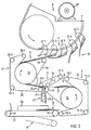
- FIG. 1 shows a process diagram of the process according to the invention, with the various formations that the printed products have between the feed by the feed belt conveyor and the transport away by the feed conveyor with the letters A, B, C, D and E, the individual process steps in which The formations created are numbered 1, 2, 3 and 4.
- the general direction of conveyance is directed from left to right, although in two process steps (see the following description) the flows are turned through approximately 180 °.
- a shingled stream A in which the leading edges of the printed products lie on the top of the stream (A.1) or on the underside (A.2) and have a shingled spacing of, for example, 30 to 120 mm from one another, is fed to the method steps according to the invention.
- a first process step 1 first deflection
- the feed stream is converted into a shingle stream B with lower leading edges of the printed products, it being possible at the same time to increase or decrease the shingle spacing.
- the distances between the printed products of the scale stream B are equalized or differentiated to a stream C in a process step 2 (clocking).
- step 3 second deflection
- the shingled stream C is deflected again, so that a shingled stream D is formed in which the leading edges of the printed products or the printed product groups are directed upwards again (D.1 to D.7).
- step 4 takeover
- the printed products are taken over individually or in groups by the grippers of the conveyor and the flow E (E.1 to E.7, gripper not shown) is created.
- the first deflection (method step 1) is only necessary if the leading edges of the printed products in the feed stream A are at the top, for a stream with trailing edges below it is unnecessary in the process example described here.
- This is a deflection of the shingled stream by approx. 180 ° upwards or downwards, which usually takes place at a deflection point of a belt conveyor (first intermediate belt conveyor) while the printed products are pressed onto the conveyor belt by a pressure belt.
- the pressure belt is arranged in such a way that the scale flow is conveyed between the belt conveyor and the pressure belt, the pressure belt being moved at the same speed as the belt conveyor and exerting a pressing pressure on the scale flow.
- the distances between the printed products do not change during the transition from the infeed belt conveyor to the intermediate belt conveyor; at higher speeds of the intermediate belt conveyor, the distances increase, at lower speeds the Belt conveyor reduce the distances.
- the timing (method step 2) is effected by a timing element, which adjoins the feed belt conveyor or the first intermediate belt conveyor in the transport direction.
- Clock elements that only uniform the intervals of a shingled stream belong to the prior art.
- Corresponding elements are described, for example, in the patents EP-0254851 and US-4905981 by the same applicant, one clock element interacting with the front edges of the printed products, the other with the rear edges of the printed products.
- a clock element is required here which, depending on the setting, can not only differentiate a shingled stream supplied but also differentiate it; namely, it should not have to be replaced for these two tasks, but the changeover should be possible by means of corresponding control commands of a manual setting or central, higher-level intelligence.
- a corresponding clock element is described in connection with the following figures.
- the second function of the clock element is the transfer of the printed products to the second intermediate belt conveyor. If the speed of the second intermediate belt conveyor is the same as the speed of the belt conveyor that conveys the products to the timing element, the average distance between the printed products in the shingled stream on the second intermediate belt conveyor will be the same as before the timing element. If the speed of the second intermediate belt conveyor is greater, the distance increases; if the speed is lower, the distance between the printed products also decreases accordingly.
- a third method step 3 the scale flow created by the clock element and the speed ratios of the belt conveyors is transported to the takeover point, with it moving up or down by approximately 180 ° can be diverted below if the takeover requires leading edges of the printed products lying on the upper side of the shingled stream.
- the second intermediate belt conveyor is equipped in the same way as the first intermediate belt conveyor.
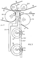
- FIG. 2 now shows schematically an exemplary embodiment of the device according to the invention. It is a device for carrying out the method with first redirection, timing and second redirection.
- the groups of device parts arranged for corresponding method steps and the created formations of printed products are designated in the figure with the same reference numbers or reference letters as in FIG. 1, that is to say: feed stream A, first deflection 1 (essentially first intermediate belt conveyor), scale flow with downward-facing front edges B, timing 2 (essentially the area between the first and second intermediate belt conveyor with timing element), uniform or differentiated scale flow with downward-pointing front edges C, second deflection 3 (essentially second intermediate belt conveyor), transfer current D , Takeover 4 (essentially the delivery area of the second intermediate belt conveyor and takeover area of the away conveyor), flow rate with grippers E.
- first deflection 1 essentially first intermediate belt conveyor
- scale flow with downward-facing front edges B
- timing 2 essentially the area between the first and second intermediate belt conveyor with timing element
- the feed stream is fed on a feed belt conveyor 5 consisting of a belt 51, a take-up roller 52 and a discharge roller 53.
- the feed belt conveyor can be flanked by side judges 54 be and can be designed such that it can be pivoted into a pivoting position 5 'if the shingled stream supplied should not be fed to the conveyor for any reason.
- the first deflection (method step 1) is implemented by a first intermediate belt conveyor.
- This has a deflection belt 11 which runs over at least two rollers, a deflection roller 12 and a delivery roller 13 and a pressure belt 14 which runs for example over four (at least three) own rollers 15.1 / 2/3/4 and over the deflection roller 12.
- a deflection belt 11 which runs over at least two rollers
- a deflection roller 12 and a delivery roller 13 and a pressure belt 14 which runs for example over four (at least three) own rollers 15.1 / 2/3/4 and over the deflection roller 12.
- a pressure belt 14 which runs for example over four (at least three) own rollers 15.1 / 2/3/4 and over the deflection roller 12.
- the four rollers 15.1 / 2/3/4 of the pressure belt one (15.4) is arranged in the area of the discharge roller 53 of the feed belt conveyor and serves as the take-up roller of the intermediate belt conveyor.
- the arrangement is such that the pressure belt 14, due to the deflection on the deflection roller 12, has a course projecting as a concave curve into the polyhedron spanned by its own rollers 15.1 / 2/3/4, the part of which facing the feed belt conveyor is approximately in the same direction has as the conveying direction of the feed belt conveyor.
- One of the rollers 12 or 13 is driven, the pressure belt 14 is towed by the deflection belt 11.
- the second intermediate belt conveyor for the second deflection (method step 3) is constructed essentially the same as the first intermediate belt conveyor, that is to say it has a deflection belt 31 with a deflection roller 32 and a delivery roller 33 and a pressure belt 34 with four separate rollers 35.1 / 2/3/4, one of which serves as a take-up roller (35.4) and is arranged in the region of the discharge roller 13 of the first intermediate belt conveyor.
- a timing element 21 is arranged between the discharge roller 13 of the first intermediate belt conveyor and the take-up roller 35.4 of the second intermediate belt conveyor.
- the scale flow is clocked in this area (process step 2), that is to say the printed products are stopped at a stop element 21.1 and lifted by a conveyor element 21.2 in a clocked manner over the stop element.
- the function and design of the clock generator are described in connection with FIGS. 3 and 4. So that the timing and the subsequent takeover of the printed products from the second intermediate belt conveyor can proceed in an orderly manner, the printed products are also above this point by a pressure belt 24, which runs over, for example, three rollers 25.1 / 2/3 and which is slightly out of motion of the moving conveyor element 21.2 its path defined by the three roles is deflected.
- the speed of the second intermediate belt conveyor depends on the spacing of the printed products necessary for a planned takeover.
- the scale flow formed in the second deflection is gripped in the area of the discharge roller 33 of the second intermediate belt conveyor by grippers 41.1 / 2/3 ... of a corresponding conveyor device 6 (method step 4).
- grippers 41.1 / 2/3 ... of a corresponding conveyor device 6 Such arrangements correspond to the cited prior art and are therefore not to be described here for this reason. It is advantageous to move the grippers in a straight line over the takeover point, as shown in the figure, until each gripped product is finally released from the stream of shingles (in the figure, grippers 41.4 and 41.5) and the grippers then only around the arc of a circle Accelerate deflection roller.
- a device as shown in FIG. 2 can, for example, be driven by a common drive 61, the drives of the individual belts having to be translated accordingly.
- the translation devices must be adjustable accordingly.
- the device shown in FIG. 2 for carrying out the method according to the invention as a variant for a shingled stream supplied with upwardly directed front edges and a takeover of printed products with likewise upwardly directed front edges offers the advantage that it can be implemented on a minimal base area while it is being used extends to the height where space is usually less limited.
- the entire device can be accommodated in an accessible housing into which the shingled stream is fed in at the bottom and the products are carried away at the top.
- FIG. 3 shows an exemplary embodiment of the clock generator 21, which has already been generally described in connection with FIG. 2.
- this figure shows: the discharge roller 13 of the first intermediate belt conveyor (it could also be the discharge roller 53 of the feed belt conveyor) ), the take-up roller 35.4 of the second intermediate belt conveyor, two rollers 25.1 / 2 of the pressure belt 24 of the timing and corresponding sections of the first deflection belt 11, the pressure belt 34 of the second deflection and the pressure belt 24 of the timing.
- the direction of transport of the printed products is indicated by the arrows F.
- the clock element 21 has a stationary stop element 21.1, the stopping end 21.1 'of which is arranged between the delivery roller 13, the take-up roller 35.4 and the pressure belt 24 in such a way that it stops printed copies transported on the conveyor belt 11 of the first intermediate belt conveyor.
- the stop element 21.1 extends transversely to the direction of transport, which allows the printed products to be stopped without moving transversely to the direction of transport. In the middle of this transverse extension, the stop element 21.1 has at least in the region of its stop end 21.1 'a gap through which the conveying element 21.2 moves.
- the conveying element 21.2 is arranged such that its conveying end 21.2 'can describe an elliptical path H in a vertical plane in the transport direction around the line which connects the two halves of the stopping end 21.1'.
- the direction of this movement is set up in such a way that the conveying end 21.2 'moves upwards while it is in the transport direction behind the stop element 21.1, downwards while it is in front of the stop element 21.1 (arrows G). So that the conveying end 21.2 'can perform such a movement, it must not be wider than the above-mentioned average gap in the stop element 21.1.
- the conveying element 21.2 is, for example, rod-shaped with a widening transversely to the transport end 21.2 'and is driven by a drive wheel 71 and a guide wheel 72.
- the axes of the two wheels are perpendicular to the direction of transport and substantially perpendicular to each other and perpendicular to the stop end 21.1 'of the stop element 21.1.
- the conveying element 21.2 is fastened to the drive wheel 71 with a rotatable fastening 73 in a pivot point P.1 (fastening point) spaced from the axis by r (fastening point) and on the guide wheel 72 in a pivot point P.2 (guiding point) spaced apart from the axis by R rotatably mounted guide 74 out.
- the diameter of the circle (2r) described by the attachment point P.1 is smaller than the diameter of the circle (2R) described by the guide point P.2. If the drive wheel 71 and the guide wheel 72 are driven at the same number of revolutions, the conveying end 21.2 'describes an ellipse, the perpendicular longer diameter of which corresponds to the diameter 2r.
- the movement of the printed products depends on the ratio of the frequency of the printed products on the belt 11 to the frequency of the elliptical movement of the conveying end 21.2 'and on the phase shift of these two movements, both parameters that can be set within a wide range without any mechanical intervention.
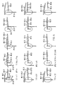
- FIG. 4 shows three examples of the function of the clock element, which is shown schematically by the stop element 21.1, the conveying element 21.2 and the elliptical movement path H of the conveying end of the conveying element 21.2 on the one hand and the printed products 80.1 / 2/3 ..., 81.1 conveyed in the area of the clock element / 2/3 ...., 82.1 / 2/3 .... on the other hand.
- the function is determined by the ratio of the circulation time of the conveying element T.1 / 2/3 to the cycle time T of the shingled stream (time that is required to convey a printed product to the position of its pre-element) and by the phase shift ⁇ .1 / 2 / 3 of the two movements, for example by the time by which the next leading edge is away from the stop element when the conveying element is in its highest position.
- the top line shows an equalization of the distances in a shingled stream supplied
- the second line shows the formation of groups of two with front edges lying one above the other
- the third line shows the formation of groups of two with differentiated distances.
- the columns represent the clock element in the same position in each case.
- the conveying element 21.2 is shown in its highest position, in the following columns after it has traveled 90 ° of its movement, so that it is again in the same position on the far right has like in the first column. Between the first and the last column, the conveyor end 21.2 'has made an elliptical movement.
- the second line of FIG. 4 shows the formation of groups of two with front edges superimposed on one another.
- the third line shows the formation of a differentiated scale flow in which the distances between the printed products after the timing are T / 2, 3T / 2, T / 2, 3T / 2 ....
- the effective spacing of the printed products after clocking also depends on the ratio of the belt speeds before and after the clock element.
- the functions of the clock element shown in FIG. 4 can be expanded almost arbitrarily by varying the ratio T / Tx and the phase shift ⁇ .x. Other variants are also possible due to other relationships between the horizontal diameter of the ellipse H and the printed product distance in front of the clock element.
Claims (16)
- Procédé pour évacuer des produits imprimés, qui sont amenés sur un convoyeur à bande d'alimentation en formation imbriquée (B), les arêtes avancées des produits étant placées au-dessous et les produits étant disposés sensiblement à intervalles égaux, les produits imprimés étant réceptionnés et évacués séparément ou par groupes par des éléments de convoyage d'évacuation (41) équidistants, caractérisé en ce que la formation imbriquée (B) amenée est transportée, par l'intermédiaire d'un générateur de rythme (21) qui agit alternativement en tant que frein et accélérateur sur les produits imprimés, dont les arêtes avancées sont placées au-dessous, sur un convoyeur à bande intermédiaire en une autre formation imbriquée (C), les intervalles entre les produits de l'autre formation imbriquée (C) étant, par comparaison à la formation imbriquée amenée, alternativement uniformes ou rythmés, et en ce que l'autre formation imbriquée (C) est transportée par le convoyeur à bande intermédiaire vers une station de réception, où les produits sont réceptionnés séparément ou par groupes par les éléments de convoyage d'évacuation (41).
- Procédé selon la revendication 1, caractérisé en ce que l'autre formation imbriquée (C) est déviée, avant d'être réceptionnée par les éléments de convoyage d'évacuation, de telle sorte que pour la réception les arêtes avancées sont placées au-dessus.
- Procédé selon la revendication 1 ou 2, caractérisé en ce qu'une formation imbriquée (A) avec des produits dont les arêtes avancées sont situées au-dessus est déviée pour être amenée en formation imbriquée avec des produits dont les arêtes avancées sont situées au-dessous.
- Procédé selon l'une quelconque des revendications 1 à 3, caractérisé en ce qu'au moins une partie des intervalles entre les produits cycliquement alternatifs est égale à zéro dans l'autre formation imbriquée (C), de telle sorte qu'au moins une partie des produits dont les arêtes avancées sont placées l'une sur l'autre soit amenée vers la station de réception et réceptionnée par les éléments de convoyage d'évacuation.
- Procédé selon l'une quelconque des revendications 1 à 4, caractérisé en ce que le convoyeur à bande intermédiaire et le convoyeur à bande d'alimentation ont des vitesses différentes.
- Procédé selon l'une quelconque des revendications 1 à 5, caractérisé en ce que le générateur de rythme (21) est muni d'un élément d'arrêt (21.1) et d'un élément d'avance (21.2), l'élément d'arrêt (21.1) bloquant par freinage les produits amenés et l'élément d'avance (21.2) transporte des produits qui cycliquement sont avancés et/ou stoppés par l'élément d'arrêt (21.1).
- Procédé selon la revendication 6, caractérisé en ce que les intervalles entre les produits dans l'autre formation imbriquée (C) sont réglables par le réglage de la fréquence et de la phase du mouvement de l'élément d'avance (21.2).
- Dispositif pour la mise en oeuvre du procédé selon l'une quelconque des revendications 1 à 7, lequel comprend un convoyeur à bande d'alimentation pour amener une formation imbriquée (B) de produits imprimés disposés sensiblement à intervalles égaux avec des arêtes avancées placées au-dessous et un convoyeur d'évacuation muni d'éléments de convoyage d'évacuation équidistants (41) pour évacuer séparément les produits imprimés ou par groupes de produits imprimés, caractérisé en ce que le dispositif est muni d'un générateur de rythme (21), qui est disposé entre le convoyeur à bande d'alimentation et le convoyeur à bande d'évacuation et agit alternativement en tant que frein et accélérateur sur les produits de la formation imbriquée (C) dont les arêtes avancées sont placées au-dessous, et d'un convoyeur à bande intermédiaire (3) disposé dans le sens du transport en aval du générateur de rythme (21) et destiné à réceptionner les produits imprimés à partir du générateur de rythme (21) et à les transporter vers une station de réception, où les produits sont interceptés par les éléments de convoyage d'évacuation (41) du convoyeur d'évacuation.
- Dispositif selon la revendication 8, caractérisé en ce que le convoyeur à bande intermédiaire est conçu comme un convoyeur de guidage (3) et comprend un tapis de transport (31), qui passe au moins autour d'une poulie de distribution (33) et une poulie de guidage (32), et une bande de serrage (34), qui passe au moins autour de trois poulies individuelles (35.1/2/3/4) et autour de la poulie de guidage (32) de la bande de guidage, la poulie individuelle (35.4) étant positionnée dans la zone du générateur de rythme (21).
- Dispositif selon la revendication 8 ou 9, caractérisé en ce qu'un autre convoyeur à bande intermédiaire (1) est disposé entre le convoyeur à bande d'alimentation et le générateur de rythme (21), et en ce que cet autre convoyeur à bande intermédiaire est conçu comme un convoyeur à bande de guidage.
- Dispositif selon l'une quelconque des revendications 8 à 10, caractérisé en ce que le générateur de rythme (21) est muni d'un élément d'arrêt fixe (21.1) et d'un élément d'avance mobile (21.2).
- Dispositif selon la revendication 11, caractérisé en ce que l'élément d'arrêt (21.1) s'étend transversalement par rapport au sens de transport et comprend une cavité réalisée dans la zone centrale, et en ce que l'élément d'avance (21.2) est disposé de telle sorte qu'il se déplace à travers cette cavité.
- Dispositif selon la revendication 12, caractérisé en ce que l'élément d'avance (21.2) est formé d'une barre dont les extrémités (21.2') sont élargies transversalement par rapport au sens de transport, en ce qu'il est monté de façon mobile sur une roue d'entraînement (71) et en ce qu'il est guidé dans un élément de guidage (74) monté de façon mobile sur une roue de guidage (72).
- Dispositif selon la revendication 13, caractérisé en ce que la roue d'entraînement (71) et la roue de guidage (72) sont disposées verticalement l'une au-dessous de l'autre et verticalement au-dessous de l'extrémité de blocage (21.1') de l'élément d'arrêt (21.1).
- Dispositif selon la revendication 14, caractérisé en ce que la distance (r) entre l'axe de la roue d'entraînement (71) et le point de fixation (P.1) est inférieure à la distance (R) entre l'axe de la roue de guidage (72) et le point de guidage (P.2).
- Dispositif selon la revendication 8, caractérisé en ce qu'au moins un autre générateur de rythme est disposé entre le générateur de rythme et le convoyeur à bande intermédiaire et en ce qu'un autre convoyeur à bande est disposé entre les deux générateurs de rythme.
Applications Claiming Priority (2)
| Application Number | Priority Date | Filing Date | Title |
|---|---|---|---|
| CH1904/91A CH683094A5 (de) | 1991-06-27 | 1991-06-27 | Verfahren und Vorrichtung zum Wegfördern von in einem Schuppenstrom zugeführten flächigen Erzeugnissen, insbesondere Druckprodukten. |
| CH1904/91 | 1991-06-27 |
Publications (2)
| Publication Number | Publication Date |
|---|---|
| EP0520944A1 EP0520944A1 (fr) | 1992-12-30 |
| EP0520944B1 true EP0520944B1 (fr) | 1996-05-01 |
Family
ID=4221316
Family Applications (1)
| Application Number | Title | Priority Date | Filing Date |
|---|---|---|---|
| EP92810456A Expired - Lifetime EP0520944B1 (fr) | 1991-06-27 | 1992-06-12 | Procédé et dispositif pour enlever des articles plats arrivant en formation imbriquée, en particulier des produits imprimés |
Country Status (10)
| Country | Link |
|---|---|
| US (1) | US5295679A (fr) |
| EP (1) | EP0520944B1 (fr) |
| JP (1) | JP3325606B2 (fr) |
| AT (1) | ATE137474T1 (fr) |
| AU (1) | AU653826B2 (fr) |
| CA (1) | CA2071274A1 (fr) |
| CH (1) | CH683094A5 (fr) |
| DE (1) | DE59206153D1 (fr) |
| FI (1) | FI922988A (fr) |
| RU (1) | RU2074096C1 (fr) |
Families Citing this family (16)
| Publication number | Priority date | Publication date | Assignee | Title |
|---|---|---|---|---|
| US5586964A (en) * | 1994-11-02 | 1996-12-24 | B. Bunch Company, Inc. | System for delivering folded paper |
| JP3793232B2 (ja) * | 1995-04-11 | 2006-07-05 | グラファ−ホルディング・アクチェンゲゼルシャフト | 印刷物ストリームの搬送方法及び装置 |
| US5882006A (en) * | 1995-10-06 | 1999-03-16 | Baldwin Technology Corporation | Apparatus and method for turning and orienting articles within an article pathway |
| EP0863099B1 (fr) * | 1997-03-04 | 2001-11-21 | Ferag AG | Dispositif pour séparer des produits imprimés empilés |
| US6193227B1 (en) * | 1997-04-28 | 2001-02-27 | Grapha-Holding Ag | Continuously feeding sheets with coil unwind control |
| EP0990535B1 (fr) * | 1998-09-28 | 2003-11-12 | Grapha-Holding Ag | Méhode pour fabriquer des produits d'imprimerie par insertion d'au moins un produit constituant dans un produit principal et dispositif pour mettre en oeuvre la méthode |
| EP1124747B1 (fr) * | 1998-10-26 | 2003-11-12 | Ferag AG | Procede et dispositif d'alimentation en imprimes |
| ATE259751T1 (de) | 1999-05-31 | 2004-03-15 | Ferag Ag | Verfahren und vorrichtung zum transportieren von in einer schuppenformation anfallenden gegenständen |
| US6227532B1 (en) | 1999-06-21 | 2001-05-08 | Gbr Systems Corporation | Sheet turnover mechanism |
| DK1193201T3 (da) * | 2000-10-02 | 2004-03-08 | Ferag Ag | Fremgangsmåde og anordning til dannelse af en dobbeltskelformation af trykkeriprodukter |
| EP1227052B1 (fr) * | 2001-01-24 | 2004-08-11 | Ferag AG | Procédé et dispositif pour changer la position de saisie des objets plats, convoyés par des pinces |
| ATE337996T1 (de) * | 2001-12-21 | 2006-09-15 | Ferag Ag | Verfahren und vorrichtung zum födern von flächigen produkten |
| DK1494949T3 (da) * | 2002-04-18 | 2009-01-19 | Ferag Ag | Fremgangsmåde og indretning til fremföring af et respektivt antal flade underprodukter til en seriel videreforarbejdning |
| JP3895726B2 (ja) | 2003-12-26 | 2007-03-22 | 株式会社東京機械製作所 | 折帳集積装置 |
| EP2243734B1 (fr) * | 2009-04-23 | 2011-10-26 | Müller Martini Holding AG | Procédé de retournement de produits d'impression transportés sur une trajectoire de transport dans un flux de transport |
| CH702403A1 (de) * | 2009-12-07 | 2011-06-15 | Ferag Ag | Verfahren zum Entkoppeln zweier aufeinanderfolgender Produkteströme von Druckprodukten sowie Vorrichtung zur Durchführung des Verfahrens. |
Family Cites Families (5)
| Publication number | Priority date | Publication date | Assignee | Title |
|---|---|---|---|---|
| CH618398A5 (fr) * | 1977-06-06 | 1980-07-31 | Ferag Ag | |
| CH630583A5 (de) * | 1978-06-30 | 1982-06-30 | Ferag Ag | Vorrichtung zum wegfoerdern von in einem schuppenstrom anfallenden flaechigen erzeugnissen, insbesondere druckprodukten. |
| US4204286A (en) * | 1978-12-11 | 1980-05-27 | Gem Industries Inc. | Spring support |
| CH637091A5 (de) * | 1979-01-29 | 1983-07-15 | Ferag Ag | Vorrichtung zum zufuehren von in einem schuppenstrom anfallenden flaechigen erzeugnissen, insbesondere druckprodukten, zu einem transporteur. |
| CH677778A5 (fr) * | 1988-03-14 | 1991-06-28 | Ferag Ag |
-
1991
- 1991-06-27 CH CH1904/91A patent/CH683094A5/de not_active IP Right Cessation
-
1992
- 1992-06-12 AT AT92810456T patent/ATE137474T1/de not_active IP Right Cessation
- 1992-06-12 EP EP92810456A patent/EP0520944B1/fr not_active Expired - Lifetime
- 1992-06-12 DE DE59206153T patent/DE59206153D1/de not_active Expired - Fee Related
- 1992-06-15 CA CA002071274A patent/CA2071274A1/fr not_active Abandoned
- 1992-06-19 AU AU18401/92A patent/AU653826B2/en not_active Ceased
- 1992-06-25 JP JP19343892A patent/JP3325606B2/ja not_active Expired - Fee Related
- 1992-06-26 US US07/904,703 patent/US5295679A/en not_active Expired - Fee Related
- 1992-06-26 FI FI922988A patent/FI922988A/fi unknown
- 1992-06-26 RU SU925052250A patent/RU2074096C1/ru active
Also Published As
| Publication number | Publication date |
|---|---|
| FI922988A0 (fi) | 1992-06-26 |
| AU1840192A (en) | 1993-01-07 |
| DE59206153D1 (de) | 1996-06-05 |
| RU2074096C1 (ru) | 1997-02-27 |
| FI922988A (fi) | 1992-12-28 |
| US5295679A (en) | 1994-03-22 |
| CH683094A5 (de) | 1994-01-14 |
| JPH0664819A (ja) | 1994-03-08 |
| AU653826B2 (en) | 1994-10-13 |
| EP0520944A1 (fr) | 1992-12-30 |
| CA2071274A1 (fr) | 1992-12-28 |
| JP3325606B2 (ja) | 2002-09-17 |
| ATE137474T1 (de) | 1996-05-15 |
Similar Documents
| Publication | Publication Date | Title |
|---|---|---|
| EP0520944B1 (fr) | Procédé et dispositif pour enlever des articles plats arrivant en formation imbriquée, en particulier des produits imprimés | |
| EP0399264B1 (fr) | Procédé et dispositif pour changer la position relative de paquets, en particulier de paquets de cigarettes parallélépipédiques du type à couvercle articulé (hinge-lid) | |
| DE3742404C2 (de) | Verfahren und Vorrichtung zur Übergabe von Produkten | |
| DE3735486C2 (fr) | ||
| EP1498370B1 (fr) | Dispositif pour orienter des articles | |
| DE3508416C2 (fr) | ||
| EP3372538A1 (fr) | Section de transport, procédé de réglage et/ou de positionnement d'au moins une bande transporteuse à l'intérieur d'une section de transport et installation d'emballage | |
| EP1914165B1 (fr) | Procédé et dispositif destinés à former une rangée d'objets plats | |
| DE2948589A1 (de) | Vorrichtung zur verteilung von behaeltern in mehreren reihen und anlage, die diese vorrichtung einsetzt | |
| EP0503531A1 (fr) | Dispositif pour former une suite d'objets se chevauchant par le dessous | |
| EP0417503A1 (fr) | Procédé et dispositif pour le traitement ultérieur de produits imprimés empilés, de préférence pliés | |
| DE3438268C2 (fr) | ||
| EP3450359A1 (fr) | Dispositif et procédé de manipulation d'au moins une rangée de marchandises en mouvement les unes derrière les autres | |
| EP0956253A1 (fr) | Procede et dispositif pour separer ou reunir des series de corps de contenants | |
| EP3375737A1 (fr) | Section de transport et procédé de réglage et/ou de positionnement d'au moins un rail de transport à l'intérieur d'une section de transport | |
| DE1900615A1 (de) | Vorrichtung zum Palettieren,insbesondere fuer Schlauchabschnittpakete | |
| EP2281765A2 (fr) | Dispositif et procédé correspondant pour déposer des produits | |
| EP1309504A1 (fr) | Procede et dispositif de production de piles en croix | |
| EP1432633A1 (fr) | Procede pour traiter des produits plans et dispositif pour mettre ledit procede en oeuvre | |
| AT516092B1 (de) | Vorrichtung und Verfahren zum Transport von schlauchförmigen Sackkörpern | |
| EP3456668B1 (fr) | Dispositif de transport pour découpes à plat de boîtes pliantes | |
| EP2507155A1 (fr) | Procédé et dispositif pour dévier un flux d'objets plats flexibles | |
| EP1312568B1 (fr) | Assembleuse pour former des livres non reliés | |
| DE4314644A1 (de) | Vorrichtung zum Ablegen flacher Gegenstände in Hochkantlage auf einem Transportband oder dergleichen | |
| WO1996005732A1 (fr) | Appareil a produire des bretzels |
Legal Events
| Date | Code | Title | Description |
|---|---|---|---|
| PUAI | Public reference made under article 153(3) epc to a published international application that has entered the european phase |
Free format text: ORIGINAL CODE: 0009012 |
|
| AK | Designated contracting states |
Kind code of ref document: A1 Designated state(s): AT CH DE ES FR GB IT LI NL SE |
|
| 17P | Request for examination filed |
Effective date: 19930607 |
|
| 17Q | First examination report despatched |
Effective date: 19940606 |
|
| GRAH | Despatch of communication of intention to grant a patent |
Free format text: ORIGINAL CODE: EPIDOS IGRA |
|
| GRAA | (expected) grant |
Free format text: ORIGINAL CODE: 0009210 |
|
| AK | Designated contracting states |
Kind code of ref document: B1 Designated state(s): AT CH DE ES FR GB IT LI NL SE |
|
| PG25 | Lapsed in a contracting state [announced via postgrant information from national office to epo] |
Ref country code: NL Free format text: LAPSE BECAUSE OF FAILURE TO SUBMIT A TRANSLATION OF THE DESCRIPTION OR TO PAY THE FEE WITHIN THE PRESCRIBED TIME-LIMIT Effective date: 19960501 Ref country code: IT Free format text: LAPSE BECAUSE OF FAILURE TO SUBMIT A TRANSLATION OF THE DESCRIPTION OR TO PAY THE FEE WITHIN THE PRE;WARNING: LAPSES OF ITALIAN PATENTS WITH EFFECTIVE DATE BEFORE 2007 MAY HAVE OCCURRED AT ANY TIME BEFORE 2007. THE CORRECT EFFECTIVE DATE MAY BE DIFFERENT FROM THE ONE RECORDED.SCRIBED TIME-LIMIT Effective date: 19960501 Ref country code: GB Effective date: 19960501 Ref country code: FR Effective date: 19960501 Ref country code: ES Free format text: THE PATENT HAS BEEN ANNULLED BY A DECISION OF A NATIONAL AUTHORITY Effective date: 19960501 |
|
| REF | Corresponds to: |
Ref document number: 137474 Country of ref document: AT Date of ref document: 19960515 Kind code of ref document: T |
|
| REG | Reference to a national code |
Ref country code: CH Ref legal event code: NV Representative=s name: FREI PATENTANWALTSBUERO |
|
| REF | Corresponds to: |
Ref document number: 59206153 Country of ref document: DE Date of ref document: 19960605 |
|
| PG25 | Lapsed in a contracting state [announced via postgrant information from national office to epo] |
Ref country code: AT Effective date: 19960612 |
|
| EN | Fr: translation not filed | ||
| NLV1 | Nl: lapsed or annulled due to failure to fulfill the requirements of art. 29p and 29m of the patents act | ||
| GBV | Gb: ep patent (uk) treated as always having been void in accordance with gb section 77(7)/1977 [no translation filed] |
Effective date: 19960501 |
|
| PLBE | No opposition filed within time limit |
Free format text: ORIGINAL CODE: 0009261 |
|
| STAA | Information on the status of an ep patent application or granted ep patent |
Free format text: STATUS: NO OPPOSITION FILED WITHIN TIME LIMIT |
|
| 26N | No opposition filed | ||
| PGFP | Annual fee paid to national office [announced via postgrant information from national office to epo] |
Ref country code: CH Payment date: 20020510 Year of fee payment: 11 |
|
| PGFP | Annual fee paid to national office [announced via postgrant information from national office to epo] |
Ref country code: SE Payment date: 20020531 Year of fee payment: 11 |
|
| PGFP | Annual fee paid to national office [announced via postgrant information from national office to epo] |
Ref country code: DE Payment date: 20020603 Year of fee payment: 11 |
|
| PG25 | Lapsed in a contracting state [announced via postgrant information from national office to epo] |
Ref country code: SE Free format text: LAPSE BECAUSE OF NON-PAYMENT OF DUE FEES Effective date: 20030613 |
|
| PG25 | Lapsed in a contracting state [announced via postgrant information from national office to epo] |
Ref country code: LI Free format text: LAPSE BECAUSE OF NON-PAYMENT OF DUE FEES Effective date: 20030630 Ref country code: CH Free format text: LAPSE BECAUSE OF NON-PAYMENT OF DUE FEES Effective date: 20030630 |
|
| PG25 | Lapsed in a contracting state [announced via postgrant information from national office to epo] |
Ref country code: DE Free format text: LAPSE BECAUSE OF NON-PAYMENT OF DUE FEES Effective date: 20040101 |
|
| EUG | Se: european patent has lapsed | ||
| REG | Reference to a national code |
Ref country code: CH Ref legal event code: PL |