EP0520080B2 - Connecteur pour des cartes à puce - Google Patents
Connecteur pour des cartes à puce Download PDFInfo
- Publication number
- EP0520080B2 EP0520080B2 EP91110707A EP91110707A EP0520080B2 EP 0520080 B2 EP0520080 B2 EP 0520080B2 EP 91110707 A EP91110707 A EP 91110707A EP 91110707 A EP91110707 A EP 91110707A EP 0520080 B2 EP0520080 B2 EP 0520080B2
- Authority
- EP
- European Patent Office
- Prior art keywords
- cover
- card
- base member
- contacts
- card connector
- Prior art date
- Legal status (The legal status is an assumption and is not a legal conclusion. Google has not performed a legal analysis and makes no representation as to the accuracy of the status listed.)
- Expired - Lifetime
Links
- 239000003989 dielectric material Substances 0.000 claims description 6
- 239000007769 metal material Substances 0.000 claims description 6
- 230000000295 complement effect Effects 0.000 claims description 2
- 230000000694 effects Effects 0.000 claims description 2
- 230000000712 assembly Effects 0.000 description 2
- 238000000429 assembly Methods 0.000 description 2
- 230000015654 memory Effects 0.000 description 2
- 230000036316 preload Effects 0.000 description 2
- 238000010276 construction Methods 0.000 description 1
- 230000002950 deficient Effects 0.000 description 1
- 230000005611 electricity Effects 0.000 description 1
- 238000004519 manufacturing process Methods 0.000 description 1
- 239000000463 material Substances 0.000 description 1
- 230000003068 static effect Effects 0.000 description 1
Images
Classifications
-
- H—ELECTRICITY
- H01—ELECTRIC ELEMENTS
- H01R—ELECTRICALLY-CONDUCTIVE CONNECTIONS; STRUCTURAL ASSOCIATIONS OF A PLURALITY OF MUTUALLY-INSULATED ELECTRICAL CONNECTING ELEMENTS; COUPLING DEVICES; CURRENT COLLECTORS
- H01R13/00—Details of coupling devices of the kinds covered by groups H01R12/70 or H01R24/00 - H01R33/00
- H01R13/02—Contact members
- H01R13/22—Contacts for co-operating by abutting
- H01R13/24—Contacts for co-operating by abutting resilient; resiliently-mounted
- H01R13/2442—Contacts for co-operating by abutting resilient; resiliently-mounted with a single cantilevered beam
-
- G—PHYSICS
- G06—COMPUTING; CALCULATING OR COUNTING
- G06K—GRAPHICAL DATA READING; PRESENTATION OF DATA; RECORD CARRIERS; HANDLING RECORD CARRIERS
- G06K7/00—Methods or arrangements for sensing record carriers, e.g. for reading patterns
- G06K7/0013—Methods or arrangements for sensing record carriers, e.g. for reading patterns by galvanic contacts, e.g. card connectors for ISO-7816 compliant smart cards or memory cards, e.g. SD card readers
- G06K7/0021—Methods or arrangements for sensing record carriers, e.g. for reading patterns by galvanic contacts, e.g. card connectors for ISO-7816 compliant smart cards or memory cards, e.g. SD card readers for reading/sensing record carriers having surface contacts
-
- H—ELECTRICITY
- H01—ELECTRIC ELEMENTS
- H01R—ELECTRICALLY-CONDUCTIVE CONNECTIONS; STRUCTURAL ASSOCIATIONS OF A PLURALITY OF MUTUALLY-INSULATED ELECTRICAL CONNECTING ELEMENTS; COUPLING DEVICES; CURRENT COLLECTORS
- H01R12/00—Structural associations of a plurality of mutually-insulated electrical connecting elements, specially adapted for printed circuits, e.g. printed circuit boards [PCB], flat or ribbon cables, or like generally planar structures, e.g. terminal strips, terminal blocks; Coupling devices specially adapted for printed circuits, flat or ribbon cables, or like generally planar structures; Terminals specially adapted for contact with, or insertion into, printed circuits, flat or ribbon cables, or like generally planar structures
- H01R12/70—Coupling devices
- H01R12/82—Coupling devices connected with low or zero insertion force
- H01R12/83—Coupling devices connected with low or zero insertion force connected with pivoting of printed circuits or like after insertion
Definitions
- This invention relates to an IC card connector as described in the preamble of claim 1.
- IC card connectors having a cover with a hollow in it to accomondate the IC card are known from DE 36 42 424 and US-A-4 820 186.
- an IC card connector without a cover EP-A-0 214 278, It is also known to construct an IC card connector without a cover (EP-A-0 214 278). Here, too, a slot-like hollow is provided for accommodating the IC card.
- An IC card connector of the kind referred-to above is shown in a hand set of a radio telephone (DE-A-38 22 848).
- a printed circuit board having contacts on it is arranged in a housing which has an opening and a cover to close it.
- the inner side of the cover is provided with guiding means in the form of rails made up of the plastic material of the cover, to receive the IC card so that when closing the cover, the contacts on the printed circuit board and the IC card cooperate.
- IC cards have been developed and contain IC's (integrated circuits) including memory circuits, such as RAMs (random access memories), and control circuits, such as CPUs (central processing units).
- the IC cards normally include a terminal array for connection through a card reader system to external equipment such as a printed circuit board.
- the connector usually includes some form of IC card socket and a plurality of electrodes or contacts exposed in the socket for engaging the terminal array of the IC card. The card is inserted and removed from the socket, and the connector contacts are resilient or comprise springy contacts for yieldably engaging the terminal array of the card when the card is inserted into the socket.
- the integrated circuits can be harmed or even destroyed by static electricity resulting from contaminated circuits when the terminal array on the card comes in contact with the hand of a user when the user attempts to position the tiny card into the socket of the connector in proper engagement with the connector contacts.
- This invention is directed to solving the above problems in a miniature IC card connector which is extremely simple to manufacture and assemble.
- An object, therefore, of the invention is to provide a new and improved IC card connector for connecting an IC card having a terminal array, in an IC card reader system or the like.
- the IC card connector includes a base member having a plurality of electrically conductive contacts exposed on one side thereof.
- a cover is hinged to the base member for movement toward and away from the one side.
- the cover has receptacle means for securing the IC card thereon for movement therewith, whereby closing the cover onto the base member effects engagement of the IC card terminals with the contacts on the base member.
- the base member is provided as a unitarily molded component of dielectric material such as plastic or the like.
- the cover is fabricated of metal material to provide shielding for the IC card.
- the cover is fabricated in one-piece from stamped and formed sheet metal material.
- the cover has flanges providing means for slidably receiving the IC card in an edge-wise fashion.
- the card reader system may include a printed circuit board and, in such an application, the base member is illustrated herein as including means for mounting the base member to the printed circuit board with the contacts engageable with circuit traces on the board.
- the contacts have resilient portions exposed on the one side of the base member for engaging the terminal array of the IC card.
- Another feature of an embodiment of the invention is the provision of complementary interengaging latch means between the unitarily molded base member and the one-piece cover to hold the cover in a closed position with the IC terminal array in engagement with the contacts on the base member.
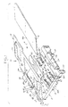
- Figure 1 shows an IC card 16 about to be inserted into cover 14 in the direction of arrow "A".
- the IC card is a miniature card of conventional or known construction and includes a terminal array on the bottom side thereof (not visible in Figure 1).
- base member 12 includes a generally flat base portion 18 having a raised area 20.
- Hinge means including a pair of rearwardly projecting trough portions 22 and hook portions 24, are provided at the rear of base portion 18.
- a latch flange 26 projects forwardly of base portion 18 and defines a latch shoulder 28.
- a plurality of mounting pegs 30 depend from the underside of base portion 18 for mounting in appropriate mounting holes in a printed circuit board, for instance.
- a plurality of slots 32 and a plurality of through apertures 34 are provided for mounting a plurality of contacts, generally designated 36, on base member 12, as will be described in greater detail hereinafter, whereby portions of the contacts are exposed on the top side of the base member as can be seen in Figures 1 and 2.
- Base member 12 including all of the elements thereof described above, including trough portions 22, hook portions 24, latch flange 26, and mounting pegs 30, comprises a unitarily molded single component of dielectric material, such as plastic or the like.
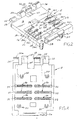
- each contact 36 includes a generally horizontal leg 36a terminating at one end in a foot 36b.
- the contacts are formed with a resilient or springy leg 36c which is bent back over horizontal leg 36a whereby the resilient leg projects upwardly beyond the top surface of the base member so as to be exposed on the top side thereof.
- Each contact 36 is mounted on the base member by a mounting flange or boss portion 36d which is press-fit into a respective aperture 34 in the base member.
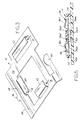
- the base member is shown in Figure 5 as being mounted to a printed circuit board 40 by means of mounting pegs 30 inserted through appropriate mounting holes in the printed circuit board.
- feet 36b of the contacts are maintained in surface contact with appropriate circuit traces on the top of the printed circuit board.
- cover 14 is a one-piece component fabricated of either stamped and formed sheet metal material or molded dielectric material, such as plastic or the like.
- the cover includes a thin, flat body 44, a guide tongue 46 projecting from the rear of the body, a rear slot 48 extending transversely of the body, a latch arm 50 disposed at the front of the body, a pair of side flanges 52 formed to be spaced slightly above the top of the body and a similar rear flange 54.
- Flanges 52 and 54 all project toward the middle of the body to define receptacle means, as indicated by arrows "B" for IC card 16 between the top of body 44 and the undersides of flanges 52 and 54.
- Cover 14 being assembled to base member 12 as shown in Figure 1, provides a carrier for IC card 16 whereby the cover itself is the moving medium for the IC card, rather than having to position the card in a receptacle of the base member by manual manipulation, as is prevalent in the prior art.
- an operator simply grasps the IC card by its edges, to preclude the possibility of touching the terminal array of the card, and inserts the card edge-wise in the direction of arrow "A" beneath and between side flanges 52 of the cover in the preload position as shown in Fig. 1 until a leading edge 16a of the IC card becomes seated beneath rear flange 54 of the cover.
- cover 14 and its received IC card 16 then can be closed downwardly onto the top of base member 12, as indicated by arrow "D" in Figure 1, without any further touching of the IC card by an operator.
- the terminal array on the underside of the IC card engage resilient legs 36c of selective ones of contacts 36, the resilient legs being springy and yieldable to maintain a secure contact engagement between the terminals and the contacts.
- latch arm 50 at the front of cover 14 snaps behind shoulder 28 of latch flange 26 of the base memberto latch the cover in fully closed condition and with the IC card terminal array securely terminated to contacts 36.
- the latch arm is cantilevered, as shown, and its resiliency draws the cover into secure engagement with hook portions 24 of the base member.
- an extremely simple IC card connector has been provided by only two basic components, namely base member 12 and cover 14, along with the contacts 36 mounted on the base member.
- An IC card is positioned on the cover for movement therewith to eliminate touching the IC card except at its edges as it is inserted between and beneath flanges 52 and 54 of the cover. No touching whatsoever is required of the IC card to move the card into engagement with contacts 36 and/or mount the IC card onto the base member.
Landscapes
- Engineering & Computer Science (AREA)
- Artificial Intelligence (AREA)
- Computer Vision & Pattern Recognition (AREA)
- Physics & Mathematics (AREA)
- General Physics & Mathematics (AREA)
- Theoretical Computer Science (AREA)
- Details Of Connecting Devices For Male And Female Coupling (AREA)
- Coupling Device And Connection With Printed Circuit (AREA)
- Connecting Device With Holders (AREA)
Claims (8)
- Connecteur (10) de carte à puce pour connecter une carte à puce (16) ayant un groupement de bornes dans un système de lecteur de carte à puce, comportant :grâce à quoi la fermeture du couvercle (14) sur l'élément de base (12) fait entrer en engagement le groupement de bornes de la carte à puce avec les contacts (36) dans l'élément de base,un élément de base (12) dans lequel sont agencés une pluralité de contacts électriquement conducteurs (36), les contacts (36) ayant des côtés qui sont mis à nu pour engager le groupement de bornes de la carte à puce ; etun couvercle (14) monté sur l'élément de base (12) de façon à se rapprocher et s'éloigner des contacts (36), le couvercle ayant un corps (44) et un moyen à réceptacle (52, 54) comprenant une paire de rebords latéraux (52) qui sont légèrement espacés du corps du couvercle (14), pour fixer la carte à puce (16) sur lui afin qu'elle se déplace avec lui, lesdits rebords (52) formant chacun une structure en forme de L en section transversale et étant conçus pour être placés à des bords opposés de ladite carte à puce (16), lorsque ladite carte à puce (16) est totalement insérée dans ledit moyen à réceptacle (52, 54),
caractérisé en ce que
l'élément de base (12) est prévu sous la forme d'un constituant moulé d'un seul tenant en matière diélectrique et comporte un moyen formant charnière (22, 24) pour le montage du couvercle (14) sur l'élément de base (12), qui comprend une partie de base globalement plate (18) ayant une zone surélevée (20) définissant une surface supérieure, et un moyen de montage (30) sur le côté inférieur de la partie de base pour le montage de l'élément de base (12) sur une plaquette (40) à circuit imprimé qui comporte des pistes de circuit ;
en ce que chacun desdits contacts (36) comprend une branche globalement horizontale (36a) se terminant à une extrémité par un pied (36b) qui peut être engagé avec lesdites pistes de circuit sur la plaquette (40) à circuit, les contacts (36) ayant aussi chacun une partie de montage (36d) et une branche élastique recourbée (36c) qui fait saillie vers le haut au-delà de la surface supérieure de la zone surélevée (20) de l'élément de base,
ledit couvercle (14) est un constituant d'une seule pièce fabriqué soit en matière métallique en feuille estampée formée, soit en matière diélectrique moulée et présente, en opposition auxdits contacts (36), une ouverture et peut être fermé en étant abaissé sur la zone surélevée (20) afin que les branches élastiques (36c) des contacts s'étendent dans l'ouverture lorsque le couvercle est fermé,
et en ce que
lesdits rebords latéraux (52) et un rebord arrière similaire (54) font saillie vers le milieu du corps (44) du couvercle (14) pour définir ledit moyen réceptacle où l'ouverture dans le couvercle (14) est agencée, afin de maintenir ladite carte à puce (16) au-dessus de ladite ouverture et sur le dessus du corps (44) du couvercle (14). - Connecteur de carte à puce selon la revendication 1, dans lequel ledit couvercle (14) est fait d'une matière métallique pour réaliser un blindage pour la carte à puce.
- Connecteur de carte à puce selon la revendication 2, dans lequel ledit couvercle (14) est fait d'une seule pièce à partir d'une matière métallique en feuille emboutie et formée.
- Connecteur de carte à puce selon l'une quelconque des revendications 1 à 3, dans lequel ledit élément base (12) est moulé d'un seul tenant à partir d'une matière diélectrique.
- Connecteur de carte à puce selon l'une quelconque des revendications 1 à 4, incluant un moyen de verrouillage réciproque complémentaire (26, 28, 50) entre l'élément base (12) et le couvercle (14) pour maintenir le couvercle en position fermée, le réseau de bornes de carte à puce étant en contact avec les contacts (36) sur l'élément base.
- Connecteur de carte à puce selon la revendication 5, dans lequel ledit moyen de verrouillage (26, 28, 50) comprend une partie de verrouillage rigide (26, 28) sur l'élément base moulé d'un seul tenant et un bras de verrouillage élastique (50) sur le couvercle embouti et formé.
- Connecteur de carte à puce selon l'une quelconque des revendications 1 à 6, comprenant un moyen formant charnière (22, 24, 48, 56, 58) pour monter ledit couvercle (14) sur ledit élément base (12).
- Connecteur de carte à puce selon l'une quelconque des revendications 1 à 7, dans lequel ledit élément base (12) est globalement plat et ledit couvercle (14) est relativement mince.
Priority Applications (5)
| Application Number | Priority Date | Filing Date | Title |
|---|---|---|---|
| ES91110707T ES2061121T3 (es) | 1991-06-28 | 1991-06-28 | Conectador de tarjeta de c i (circuitos integrados). |
| DE69104350T DE69104350T2 (de) | 1991-06-28 | 1991-06-28 | Verbinder für IC-Karten. |
| EP91110707A EP0520080B2 (fr) | 1991-06-28 | 1991-06-28 | Connecteur pour des cartes à puce |
| US07/901,053 US5226826A (en) | 1991-06-28 | 1992-06-19 | Ic card connector |
| JP1992050543U JP2539188Y2 (ja) | 1991-06-28 | 1992-06-25 | Icカードドライブ装置 |
Applications Claiming Priority (1)
| Application Number | Priority Date | Filing Date | Title |
|---|---|---|---|
| EP91110707A EP0520080B2 (fr) | 1991-06-28 | 1991-06-28 | Connecteur pour des cartes à puce |
Publications (3)
| Publication Number | Publication Date |
|---|---|
| EP0520080A1 EP0520080A1 (fr) | 1992-12-30 |
| EP0520080B1 EP0520080B1 (fr) | 1994-09-28 |
| EP0520080B2 true EP0520080B2 (fr) | 2005-03-30 |
Family
ID=8206874
Family Applications (1)
| Application Number | Title | Priority Date | Filing Date |
|---|---|---|---|
| EP91110707A Expired - Lifetime EP0520080B2 (fr) | 1991-06-28 | 1991-06-28 | Connecteur pour des cartes à puce |
Country Status (5)
| Country | Link |
|---|---|
| US (1) | US5226826A (fr) |
| EP (1) | EP0520080B2 (fr) |
| JP (1) | JP2539188Y2 (fr) |
| DE (1) | DE69104350T2 (fr) |
| ES (1) | ES2061121T3 (fr) |
Families Citing this family (64)
| Publication number | Priority date | Publication date | Assignee | Title |
|---|---|---|---|---|
| US5314355A (en) * | 1992-06-01 | 1994-05-24 | Xerox Corporation | Coplainer sliding electrical connector |
| US5836775A (en) * | 1993-05-13 | 1998-11-17 | Berg Tehnology, Inc. | Connector apparatus |
| FR2707433B1 (fr) * | 1993-07-08 | 1995-08-18 | Pontarlier Connectors | Connecteur pour carte, en particulier pour carte électronique. |
| FR2714539B1 (fr) * | 1993-12-24 | 1996-01-26 | Itt Composants Instr | Connecteur électrique pour le raccordement d'une carte à mémoire électronique. |
| US5426701A (en) * | 1994-02-28 | 1995-06-20 | General Instrument Corporation Of Delaware | Cable television converter box with a smart card connector underneath |
| FR2718548B1 (fr) * | 1994-04-12 | 1996-05-15 | Cotterlaz Ets Jean | Cadre de contact pour lecteur de carte à puce. |
| DE9407499U1 (de) * | 1994-05-05 | 1995-09-07 | Itt Composants Et Instruments, Dole Cedex | Elektrisches Kontaktelement |
| JP3273226B2 (ja) * | 1994-12-07 | 2002-04-08 | ホシデン株式会社 | カードコネクタ |
| US5602581A (en) * | 1994-12-22 | 1997-02-11 | Sony Corporation | Television receiver control box that contains a card reader mounted directly to a motherboard |
| US5584706A (en) * | 1994-12-27 | 1996-12-17 | Acer Incorporated | IC card connector having two grounding contacts |
| FR2742561B1 (fr) * | 1995-12-13 | 1998-01-09 | Itt Composants Instr | Connecteur electrique pour une carte a circuit(s) integre(s) a contact |
| DE19521721B4 (de) * | 1995-06-14 | 2006-12-07 | Amphenol-Tuchel Electronics Gmbh | Geschirmte Kontaktiereinrichtung |
| GB9513540D0 (en) | 1995-07-04 | 1995-09-06 | Elco Europ Ltd | Electrical connectors |
| DE19527519C2 (de) * | 1995-07-27 | 2000-11-09 | Amphenol Tuchel Elect | Chipkartenleser mit absenkbarer Kartenführung |
| FR2743170B1 (fr) * | 1995-12-28 | 1998-02-06 | Framatome Connectors Int | Connecteur actif pour carte a puce |
| JPH09185973A (ja) * | 1995-12-28 | 1997-07-15 | Hirose Electric Co Ltd | 表面接点付カード用コネクタ |
| US6112995A (en) * | 1996-04-19 | 2000-09-05 | Siemens Aktiengesellschaft | Card reader |
| WO1997040467A1 (fr) * | 1996-04-19 | 1997-10-30 | Siemens Aktiengesellschaft | Lecteur de cartes |
| WO1998013905A1 (fr) * | 1996-09-26 | 1998-04-02 | The Whitaker Corporation | Connecteur de module electronique possedant un couvercle rotatif |
| JP2001502838A (ja) * | 1996-10-17 | 2001-02-27 | ザ ウィタカー コーポレーション | ロック用カバーを有する電子モジュール用コネクタ |
| US5969330A (en) * | 1996-11-20 | 1999-10-19 | The Whitaker Corporation | Smart card reader with hinged cover and cover actuating surface |
| US5869976A (en) * | 1996-12-13 | 1999-02-09 | Cirrus Logic, Inc. | Fine alignment IC handler and method for assembling same |
| GB2322723B (en) * | 1997-02-26 | 2000-12-20 | Whitaker Corp | Card reader having a configurable switch |
| FR2763412B1 (fr) * | 1997-05-13 | 1999-06-18 | Itt Mfg Enterprises Inc | Connecteur electrique pour une carte a circuit(s) integre(s) a contact |
| US6045367A (en) * | 1997-09-24 | 2000-04-04 | Teledyne Industries, Inc. | Multi-pin connector |
| US6024593A (en) * | 1997-10-14 | 2000-02-15 | The Whitaker Corporation | Electronic module connector having a locking cover |
| EP0917253A1 (fr) * | 1997-11-17 | 1999-05-19 | Molex Incorporated | Connecteur électrique à montage en surface |
| JPH11297415A (ja) | 1998-04-03 | 1999-10-29 | Molex Inc | カード用コネクタ |
| EP0965937B1 (fr) * | 1998-06-15 | 2006-08-09 | Molex Incorporated | Connecteur pour cartes à puces |
| EP0977139B1 (fr) | 1998-07-30 | 2000-09-27 | Molex Incorporated | Connecteur pour carte à puce |
| TW392958U (en) * | 1998-12-18 | 2000-06-01 | Hon Hai Prec Ind Co Ltd | Electronic card connector assembly |
| US6077089A (en) | 1999-01-19 | 2000-06-20 | Avx Corporation | Low profile electrical connector |
| US6273731B1 (en) | 1999-01-19 | 2001-08-14 | Avx Corporation | Low profile electrical connector |
| GB2346726B (en) | 1999-02-12 | 2003-05-07 | Nokia Mobile Phones Ltd | Mechanism for holding an intergrated circuit card |
| JP2000357210A (ja) * | 1999-05-03 | 2000-12-26 | Amphenol Tuchel Electronics Gmbh | 接触装置 |
| JP2000340281A (ja) * | 1999-05-31 | 2000-12-08 | Mitsumi Electric Co Ltd | メモリカード用コネクタ |
| US6220882B1 (en) | 1999-11-15 | 2001-04-24 | Molex Incorporated | IC card connector with release means |
| FR2803109B1 (fr) * | 1999-12-22 | 2002-03-01 | Framatome Connectors Int | Connecteur pour carte a microcircuit et procede de montage d'une telle carte dans ce connecteur |
| FR2803110B1 (fr) | 1999-12-22 | 2002-05-17 | Framatome Connectors Int | Connecteur pour carte a microcircuit et procede de montage d'une telle carte dans ce connecteur |
| WO2001097334A1 (fr) * | 2000-06-12 | 2001-12-20 | Mitsubishi Denki Kabushiki Kaisha | Connecteur de carte, plaque de montage comprenant ledit connecteur, et dispositif electronique comprenant le connecteur et la plaque de montage |
| US6334786B1 (en) * | 2000-11-14 | 2002-01-01 | Super Link Electronics Co., Ltd. | Subscriber identification module card fixing seat with slidable and laterally latching cover |
| FR2816766B1 (fr) * | 2000-11-14 | 2005-04-01 | Fci Pontarlier | Connecteur pour carte a puce avec mecanisme de verrouillage |
| JP2002280097A (ja) * | 2001-03-19 | 2002-09-27 | Jst Mfg Co Ltd | フラッシュメモリカード用コネクタおよびそれを用いた接続構造、ならびにこの接続構造を用いた電子装置 |
| JP2003178846A (ja) * | 2001-12-12 | 2003-06-27 | Tyco Electronics Amp Kk | カードコネクタ |
| DE10238156A1 (de) * | 2002-08-15 | 2004-03-04 | Lumberg Connect Gmbh & Co. Kg | Kontaktiervorrichtung für eine Chipkarte, insbesondere für eine SIM-Karte |
| JP3711540B2 (ja) * | 2002-09-17 | 2005-11-02 | 日本航空電子工業株式会社 | 薄形コネクタ |
| TW549635U (en) * | 2002-12-20 | 2003-08-21 | Hon Hai Prec Ind Co Ltd | Strengthened belectrical connector |
| TWI253284B (en) * | 2003-07-10 | 2006-04-11 | Benq Corp | Electronic device, SIM card socket and its manufacturing method |
| TWM252147U (en) * | 2003-09-19 | 2004-12-01 | Hon Hai Prec Ind Co Ltd | Electrical card connector |
| TWM251345U (en) | 2003-09-30 | 2004-11-21 | Hon Hai Prec Ind Co Ltd | Electrical card connector |
| US7161811B2 (en) * | 2004-03-12 | 2007-01-09 | Lumberg Connect Gmbh & Co. Kg | Card holder for SIM card |
| US7540742B2 (en) | 2004-08-30 | 2009-06-02 | Apple Inc. | Board connector |
| DE102004054270B4 (de) * | 2004-11-09 | 2007-06-06 | Lumberg Connect Gmbh & Co. Kg | Kontaktiervorrichtung für eine Chipkarte, insbesondere für eine SIM-Karte |
| DE102004063982A1 (de) * | 2004-11-09 | 2006-06-14 | Lumberg Connect Gmbh & Co. Kg | Kontaktiervorrichtung für eine Chipkarte, insbesondere für eine SIM-Karte |
| SG148875A1 (en) * | 2007-06-08 | 2009-01-29 | Mea Technologies Pte Ltd | Card connector |
| US8764464B2 (en) | 2008-02-29 | 2014-07-01 | Fci Americas Technology Llc | Cross talk reduction for high speed electrical connectors |
| US9277649B2 (en) | 2009-02-26 | 2016-03-01 | Fci Americas Technology Llc | Cross talk reduction for high-speed electrical connectors |
| US8616919B2 (en) | 2009-11-13 | 2013-12-31 | Fci Americas Technology Llc | Attachment system for electrical connector |
| US20110143596A1 (en) * | 2009-12-14 | 2011-06-16 | Crighton Alan D | Smart card connector |
| DE102010006655A1 (de) * | 2010-02-03 | 2011-08-04 | Amphenol-Tuchel Electronics GmbH, 74080 | SIM-Kartenleser |
| TWM482876U (zh) * | 2014-01-17 | 2014-07-21 | Wistron Corp | 電子卡連接器及裝有電子卡連接器的電子裝置 |
| JP5813817B1 (ja) * | 2014-04-18 | 2015-11-17 | 日本航空電子工業株式会社 | コネクタ及び電子機器 |
| US9760742B2 (en) | 2015-06-26 | 2017-09-12 | Echostar Technologies L.L.C. | Dual purpose press-bar and heat sink for high data transfer integrated circuit card reader |
| US10043043B1 (en) | 2017-02-07 | 2018-08-07 | DISH Technologies L.L.C. | Integrated circuit card reader with improved heat dissipation |
Family Cites Families (15)
| Publication number | Priority date | Publication date | Assignee | Title |
|---|---|---|---|---|
| US3576516A (en) * | 1968-11-13 | 1971-04-27 | Radiation Systems Inc | Quick connect-quick disconnect electrical connector |
| JPS59146955U (ja) * | 1983-03-22 | 1984-10-01 | 山一電機工業株式会社 | 被接続器体取り出し装置付接続器 |
| JPS6022778U (ja) * | 1983-07-22 | 1985-02-16 | 山一電機工業株式会社 | Icソケツト |
| DE3546780C2 (de) * | 1985-09-02 | 1996-04-25 | Amphenol Corp | Kontaktiereinrichtung für eine Chipkarte |
| US4717347A (en) * | 1985-09-30 | 1988-01-05 | Amp Incorporated | Flatpack burn-in socket |
| JPH0517720Y2 (fr) * | 1986-03-10 | 1993-05-12 | ||
| JPS634086U (fr) * | 1986-06-26 | 1988-01-12 | ||
| US4713022A (en) * | 1986-08-05 | 1987-12-15 | Pfaff Wayne | Socket for flat pack electronic device packages |
| JPH0751745Y2 (ja) * | 1986-08-20 | 1995-11-22 | 富士通株式会社 | 零挿入力コネクタ |
| JPS62261495A (ja) * | 1986-09-18 | 1987-11-13 | 株式会社東芝 | 情報記録媒体用収納体 |
| JPS63198270A (ja) * | 1987-02-12 | 1988-08-16 | 富士通株式会社 | カ−ド用コネクタ |
| US4761140A (en) * | 1987-02-20 | 1988-08-02 | Augat Inc. | Minimum insertion force self-cleaning anti-overstress PLCC receiving socket |
| EP0309198B1 (fr) * | 1987-09-21 | 1993-11-18 | Chubu Electric Power Company Inc. | Distributeur d'eau chaude à ébullition |
| JPH0633015B2 (ja) * | 1987-10-16 | 1994-05-02 | 住友金属工業株式会社 | Ic収納用金属ケース |
| JPH0238653U (fr) * | 1988-09-01 | 1990-03-14 |
-
1991
- 1991-06-28 ES ES91110707T patent/ES2061121T3/es not_active Expired - Lifetime
- 1991-06-28 DE DE69104350T patent/DE69104350T2/de not_active Expired - Lifetime
- 1991-06-28 EP EP91110707A patent/EP0520080B2/fr not_active Expired - Lifetime
-
1992
- 1992-06-19 US US07/901,053 patent/US5226826A/en not_active Expired - Lifetime
- 1992-06-25 JP JP1992050543U patent/JP2539188Y2/ja not_active Expired - Fee Related
Also Published As
| Publication number | Publication date |
|---|---|
| JPH0597066U (ja) | 1993-12-27 |
| EP0520080A1 (fr) | 1992-12-30 |
| DE69104350D1 (de) | 1994-11-03 |
| DE69104350T2 (de) | 1995-02-16 |
| EP0520080B1 (fr) | 1994-09-28 |
| US5226826A (en) | 1993-07-13 |
| ES2061121T3 (es) | 1994-12-01 |
| JP2539188Y2 (ja) | 1997-06-25 |
Similar Documents
| Publication | Publication Date | Title |
|---|---|---|
| EP0520080B2 (fr) | Connecteur pour des cartes à puce | |
| EP0977139B1 (fr) | Connecteur pour carte à puce | |
| US6053748A (en) | PC card connection unit for micro SIM card | |
| US6176721B1 (en) | IC card connector | |
| US6095868A (en) | Card reader connector having a separable cover | |
| US5572408A (en) | Card perimeter shield | |
| US7232325B2 (en) | Hinged SIM-type card holder | |
| US6106317A (en) | IC chip card connector with pivotally and linearly movable cover | |
| US7160129B2 (en) | Memory card connector with hinged cover | |
| US6220882B1 (en) | IC card connector with release means | |
| US7161811B2 (en) | Card holder for SIM card | |
| US6863537B2 (en) | Card holder for smart-card reader | |
| US6270379B1 (en) | Connector with securely retained contacts | |
| JP3216050B2 (ja) | 低背型表面取付電気コネクタ | |
| KR100208639B1 (ko) | 카드 수납 커넥터용 만능 접지 클립 | |
| US6478630B1 (en) | Electrical card connector having polarization mechanism | |
| US20050245136A1 (en) | Memory card connector with metal cover and ground terminals | |
| US5755592A (en) | Combined ground strap and board lock for electrical connector assembly | |
| US6132229A (en) | Card connector | |
| EP1059600B1 (fr) | Ensemble portable de lecture de carte intelligente | |
| JPH04229965A (ja) | ラッチ装置付き回路板用コネクタ | |
| US20080153360A1 (en) | Low profile electrical connector | |
| US4491378A (en) | Zero insertion force electrical connector | |
| US20050245120A1 (en) | Memory card connector with hinged and latched cover | |
| US6129588A (en) | Smart card connector having openings for exposing signal terminals of the connector and accommodating other electronic elements |
Legal Events
| Date | Code | Title | Description |
|---|---|---|---|
| PUAI | Public reference made under article 153(3) epc to a published international application that has entered the european phase |
Free format text: ORIGINAL CODE: 0009012 |
|
| AK | Designated contracting states |
Kind code of ref document: A1 Designated state(s): DE ES FR GB IT NL SE |
|
| 17P | Request for examination filed |
Effective date: 19930616 |
|
| 17Q | First examination report despatched |
Effective date: 19940217 |
|
| ITF | It: translation for a ep patent filed | ||
| GRAA | (expected) grant |
Free format text: ORIGINAL CODE: 0009210 |
|
| AK | Designated contracting states |
Kind code of ref document: B1 Designated state(s): DE ES FR GB IT NL SE |
|
| REF | Corresponds to: |
Ref document number: 69104350 Country of ref document: DE Date of ref document: 19941103 |
|
| ET | Fr: translation filed | ||
| REG | Reference to a national code |
Ref country code: ES Ref legal event code: FG2A Ref document number: 2061121 Country of ref document: ES Kind code of ref document: T3 |
|
| EAL | Se: european patent in force in sweden |
Ref document number: 91110707.6 |
|
| PG25 | Lapsed in a contracting state [announced via postgrant information from national office to epo] |
Ref country code: SE Effective date: 19950629 Ref country code: ES Free format text: LAPSE BECAUSE OF THE APPLICANT RENOUNCES Effective date: 19950629 |
|
| PLBI | Opposition filed |
Free format text: ORIGINAL CODE: 0009260 |
|
| 26 | Opposition filed |
Opponent name: AMPHENOL - TUCHEL ELECTRONICS GMBH Effective date: 19950628 |
|
| NLR1 | Nl: opposition has been filed with the epo |
Opponent name: AMPHENOL - TUCHEL ELECTRONICS GMBH |
|
| PLBF | Reply of patent proprietor to notice(s) of opposition |
Free format text: ORIGINAL CODE: EPIDOS OBSO |
|
| EUG | Se: european patent has lapsed |
Ref document number: 91110707.6 |
|
| REG | Reference to a national code |
Ref country code: ES Ref legal event code: FD2A Effective date: 19991007 |
|
| RDAH | Patent revoked |
Free format text: ORIGINAL CODE: EPIDOS REVO |
|
| PGFP | Annual fee paid to national office [announced via postgrant information from national office to epo] |
Ref country code: NL Payment date: 20010319 Year of fee payment: 11 |
|
| APAC | Appeal dossier modified |
Free format text: ORIGINAL CODE: EPIDOS NOAPO |
|
| APAE | Appeal reference modified |
Free format text: ORIGINAL CODE: EPIDOS REFNO |
|
| APAC | Appeal dossier modified |
Free format text: ORIGINAL CODE: EPIDOS NOAPO |
|
| REG | Reference to a national code |
Ref country code: GB Ref legal event code: IF02 |
|
| PG25 | Lapsed in a contracting state [announced via postgrant information from national office to epo] |
Ref country code: NL Free format text: LAPSE BECAUSE OF NON-PAYMENT OF DUE FEES Effective date: 20030101 |
|
| NLV4 | Nl: lapsed or anulled due to non-payment of the annual fee |
Effective date: 20030101 |
|
| PGFP | Annual fee paid to national office [announced via postgrant information from national office to epo] |
Ref country code: GB Payment date: 20040505 Year of fee payment: 14 |
|
| PGFP | Annual fee paid to national office [announced via postgrant information from national office to epo] |
Ref country code: FR Payment date: 20040602 Year of fee payment: 14 |
|
| PGFP | Annual fee paid to national office [announced via postgrant information from national office to epo] |
Ref country code: DE Payment date: 20040630 Year of fee payment: 14 |
|
| APBU | Appeal procedure closed |
Free format text: ORIGINAL CODE: EPIDOSNNOA9O |
|
| APBW | Interlocutory revision of appeal recorded |
Free format text: ORIGINAL CODE: EPIDOSNIRAPO |
|
| PUAH | Patent maintained in amended form |
Free format text: ORIGINAL CODE: 0009272 |
|
| STAA | Information on the status of an ep patent application or granted ep patent |
Free format text: STATUS: PATENT MAINTAINED AS AMENDED |
|
| 27A | Patent maintained in amended form |
Effective date: 20050330 |
|
| AK | Designated contracting states |
Kind code of ref document: B2 Designated state(s): DE ES FR GB IT NL SE |
|
| REG | Reference to a national code |
Ref country code: ES Ref legal event code: FD2A Effective date: 19950629 |
|
| PG25 | Lapsed in a contracting state [announced via postgrant information from national office to epo] |
Ref country code: IT Free format text: LAPSE BECAUSE OF NON-PAYMENT OF DUE FEES;WARNING: LAPSES OF ITALIAN PATENTS WITH EFFECTIVE DATE BEFORE 2007 MAY HAVE OCCURRED AT ANY TIME BEFORE 2007. THE CORRECT EFFECTIVE DATE MAY BE DIFFERENT FROM THE ONE RECORDED. Effective date: 20050628 Ref country code: GB Free format text: LAPSE BECAUSE OF NON-PAYMENT OF DUE FEES Effective date: 20050628 |
|
| PG25 | Lapsed in a contracting state [announced via postgrant information from national office to epo] |
Ref country code: DE Free format text: LAPSE BECAUSE OF FAILURE TO SUBMIT A TRANSLATION OF THE DESCRIPTION OR TO PAY THE FEE WITHIN THE PRESCRIBED TIME-LIMIT Effective date: 20050701 |
|
| APAH | Appeal reference modified |
Free format text: ORIGINAL CODE: EPIDOSCREFNO |
|
| PG25 | Lapsed in a contracting state [announced via postgrant information from national office to epo] |
Ref country code: FR Free format text: LAPSE BECAUSE OF NON-PAYMENT OF DUE FEES Effective date: 20060228 |
|
| GBPC | Gb: european patent ceased through non-payment of renewal fee |
Effective date: 20050628 |
|
| REG | Reference to a national code |
Ref country code: FR Ref legal event code: ST Effective date: 20060228 |
|
| EN | Fr: translation not filed |