EP0519087B1 - Verfahren zur Vorbehandlung der Oberfläche eines medizinischen Artikels - Google Patents
Verfahren zur Vorbehandlung der Oberfläche eines medizinischen Artikels Download PDFInfo
- Publication number
- EP0519087B1 EP0519087B1 EP91108146A EP91108146A EP0519087B1 EP 0519087 B1 EP0519087 B1 EP 0519087B1 EP 91108146 A EP91108146 A EP 91108146A EP 91108146 A EP91108146 A EP 91108146A EP 0519087 B1 EP0519087 B1 EP 0519087B1
- Authority
- EP
- European Patent Office
- Prior art keywords
- medical device
- chemical agent
- biological coating
- chemically active
- antithrombogenic
- Prior art date
- Legal status (The legal status is an assumption and is not a legal conclusion. Google has not performed a legal analysis and makes no representation as to the accuracy of the status listed.)
- Expired - Lifetime
Links
Images


Classifications
-
- A—HUMAN NECESSITIES
- A61—MEDICAL OR VETERINARY SCIENCE; HYGIENE
- A61L—METHODS OR APPARATUS FOR STERILISING MATERIALS OR OBJECTS IN GENERAL; DISINFECTION, STERILISATION OR DEODORISATION OF AIR; CHEMICAL ASPECTS OF BANDAGES, DRESSINGS, ABSORBENT PADS OR SURGICAL ARTICLES; MATERIALS FOR BANDAGES, DRESSINGS, ABSORBENT PADS OR SURGICAL ARTICLES
- A61L33/00—Antithrombogenic treatment of surgical articles, e.g. sutures, catheters, prostheses, or of articles for the manipulation or conditioning of blood; Materials for such treatment
- A61L33/0076—Chemical modification of the substrate
- A61L33/0088—Chemical modification of the substrate by grafting of a monomer onto the substrate
-
- A—HUMAN NECESSITIES
- A61—MEDICAL OR VETERINARY SCIENCE; HYGIENE
- A61L—METHODS OR APPARATUS FOR STERILISING MATERIALS OR OBJECTS IN GENERAL; DISINFECTION, STERILISATION OR DEODORISATION OF AIR; CHEMICAL ASPECTS OF BANDAGES, DRESSINGS, ABSORBENT PADS OR SURGICAL ARTICLES; MATERIALS FOR BANDAGES, DRESSINGS, ABSORBENT PADS OR SURGICAL ARTICLES
- A61L33/00—Antithrombogenic treatment of surgical articles, e.g. sutures, catheters, prostheses, or of articles for the manipulation or conditioning of blood; Materials for such treatment
- A61L33/0005—Use of materials characterised by their function or physical properties
- A61L33/0011—Anticoagulant, e.g. heparin, platelet aggregation inhibitor, fibrinolytic agent, other than enzymes, attached to the substrate
- A61L33/0029—Anticoagulant, e.g. heparin, platelet aggregation inhibitor, fibrinolytic agent, other than enzymes, attached to the substrate using an intermediate layer of polymer
Definitions
- the present invention relates to a method for applying an antithrombogenic biological coating to the surface of such medical device, according to the preambles of claims 1 and 2.
- a common problem in medical devices intended for blood contact is the biocompatibility of the surface of such devices.
- Medical devices, such as artificial heart valves are often in permanent or at least long-lasting contact with human or animal blood. By the way, this does not only apply to medical devices implanted or otherwise introduced into the human or animal body, but also to medical devices used in extracorporeal systems like a heart-lung machine.
- clotting coagulation
- Such clots may render the medical device (e.g. a sensor) inoperable. Further, they may reduce the free-space sectional area of a blood vessel, therefore reducing blood flow. Even worse, a clot formed on the surface of the medical device may be detached by the flowing blood and occlude a blood vessel (in particular, a capillary) thus causing thrombosis.
- the situation is even more critical in case of a catheter or an intravascular blood gas sensor introduced in a blood vessel of relatively small diameter such as the radial artery or the femoral artery.
- the catheter may be completely blocked by a clot, so that the blood pressure cannot be measured or that no blood samples can be taken; in case of an intravascular blood sensor, the active area may be blocked (i.e. no fresh blood can reach the sensor).
- a biological coating sometimes also referred to as bioactive or antithrombogenic coating.
- Coatings suited for this purposes are well-known in the art.
- a heparin-based coating such as described in United States Patent U.S. 4,810,784, may be used.
- Other suitable biocompatible materials are e.g. phosphorylcholine (EP-B-157 469) or polyester (U.S. 4,792,599). Hirudin may be used as well.
- Further biological coating materials useful as anticoagulants are known in the art.
- a common problem when applying such biological coatings to a medical device is to ensure reliable adhesion between the coating and the surface of the medical device, i.e. reliable immobilization of the coating. It is understood that a bad contact would lead to detachment of the coating, so that the medical device looses its antithrombogenic properties. As the biological coating does not adhere to the surface of the medical device by itself, additional measures have to be taken. Further, it has to be ensured that the biological coating does not loose its bioactive properties during the immobilization process.
- a known solution to this problem is to coat the surface of the medical device with a polymer and to apply the biological coating to the polymerized surface.
- the pure (uncoated) medical device is put into a polymer bath, i.e. a solvent containing dissolved polymer.
- a polymer bath i.e. a solvent containing dissolved polymer.
- the medical device is removed, its surface carries a thin film of solvent containing the polymer.
- the solvent then vaporizes, such that the pure polymer resides on the surface of the medical device.
- the biological coating is applied, e.g. by putting the medical device into an appropriate bath.
- the immobilization of a biological coating fastened on the surface of a medical device in this manner is not always reliable.
- the inventor in the present case has particularly noted that parts of the biological coating detached in use from an intervascular blood gas sensor. This has particularly happened when a medical device is stored or deposited in a liquid for a longer time period (e.g. an intravascular sensor requiring a wet or liquid environment to keep its operability even when not in use).
- Such detachment is an untolerable disadvantage of the known technique, partially because of the danger for the patient as blood clots may attach to the uncoated portions of the surface, and partially as such removal of the biological coating may affect the measuring accuracy of the sensor when parts of it are coated and others are not.
- this object is solved by performing the following steps:
- the invention makes use of a basically well-known technique called "plasma polymerization".
- plasma polymerization the object to be coated with a polymer is put in a pressure-tight chamber. Monomeres in gaseous form are then conducted into the chamber. A source of electromagnetic radiation irradiates high-frequency waves into the chamber, thereby creating a plasma (i.e. a gas containing free radicals). Even during spark discharge, temperature in the chamber is only slightly increased.
- the plasma thus created allows the monomeres to polymerize on the surface of the object.
- the polymer forms a thin layer on the surface, just like a very thin hose or tube.
- the inventor has surprisingly found that the desired effect can be achieved if not simple monomeres (as have been used in prior art techniques) are used, but monomeres with an additional functional group instead.
- plasma polymerization of monomeres with a functional group resulted in a coating which was able to keep the biological coating very reliably in place. Studies have shown that the biological coating does not detach from polymeres produced in this way, even in long-term use.
- the present invention thus overcomes the disadvantages of the prior art.
- medical devices coated with a first polymer coating according to the invention and a second (biological) coating have proven to operate very accurate (i.e. their operation is not impaired by the coating).
- This is e.g. important for medical sensors, since the sensor reading should not be influenced by either coating.
- the biological coating does adhere to the surface of the medical device over very long time periods, so that thrombosis and other negative effects are avoided. This is particularly due to the functional groups of the polymer which adhere chemically to the biological coating.
- Functional polymer as used herein means a polymer with functional groups.
- the biological coating is able to resist considerable mechanical stress.
- Intravascular blood gas sensors as such are basically known in the art, see e.g. EP-B-279 004, EP-B-336 984 and EP-A-336 985.
- the "plasma” coating generated by the inventive method has further advantages.
- such sensor consists of a variety of materials, e.g. the coating of the single sensors, the semipermeable membranes covering their diffusion zones, a sheath etc., which are all in blood contact. Therefore, if the biological coating would be directly applied to the sensor, it would cover areas of different consistency and different physical properties; it could thus happen that the biological coating does not behave in a uniform manner. E.g. its resistance to the accumulation or adhesion of clots could be varying, dependent on the covered material, or it could detach from certain areas only and remain on other areas (the latter effect is particularly disadvantageous as a limited detachment, e.g. restricted to several square micrometers, is difficult to detect, but still dangerous for the patient).
- the medical device is put in a closed, preferably pressure-tight chamber.
- the gaseous chemical agent consisting of monomer molecules chemically combined with functional groups is then allowed to stream into said chamber through an appropriate opening or valve, preferably from a container or the like filled with said chemical agent.
- a source of radiation energy is switched on.
- This source may be arranged at a side wall of the chamber or in an annular arrangement around the chamber (which preferably has a cylindrical cross section). Other suitable arrangements of the radiation source may be used as well. Because of the high intensity of the radiation, an electrically shielded chamber is preferred.
- the emitted electromagnetic waves are in the radio frequency spectrum; specifically, a frequency of 13.56 MHz (MegaHertz) has been used.
- the electromagnetic waves are irradiated into the chamber, and the spark discharge causes the gaseous chemical agent to form a "plasma”, e.g. a gas with free radicals.
- a plasma e.g. a gas with free radicals.
- the biological coating may then be applied to the polymer-coated surface in basically known manner. I.e. it is not necessary to apply the biological coating immediately to the polymer coating in order to satisfy free bondings of the polymer. Instead, the polymer-coated medical device may be removed from the chamber and then put into a chemical bath in order to apply the biological coating. It is even not necessary that the step of applying the biological coating is performed immediately after the appliance of the polymer coating; instead, the biological coating may be applied weeks later.
- the appliance of the polymer coating and the biological coating are chemically "separate" steps.
- the process of plasma polymerization may be significantly improved by the use of underpressure, i.e. a pressure below atmospheric pressure.
- a pressure-tight chamber which is approximately evacuated.
- the pressure is reduced until it is in a range from 0.01 millibar to 10 millibar, and more specifically, in a range from 0.1 millibar to 1 millibar.
- a pressure of 0.3 millibar (3 ⁇ 10 -4 bar) has been applied to the chamber, for a duration of around 20 minutes and with a RF (radiation frequency) power of 30 mW (milliwatts), with excellent results.
- the used chemical agent consists of monomeres incorporating functional groups.
- the wording "monomer molecules chemically combined with functional groups" used herein means that each (or at least the majority of) monomer molecules is combined with or bound to at least one functional group.
- Monomeres as the basis for polymerization as such are well-known in the art.
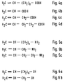
- a common basic structural formula for monomeres is wherein R n denotes hydrogen atoms, halogen, halide or organic residues or radicals (see for example Alfred Kemper/Rüdiger Fladt, Chemie, Stuttgart 1968, p. 290).
- the used monomeres are further chemically combined with (bound to) functional groups.
- Such functional groups are at least partially kept during the plasma coating process and result in a functional polymer which can covalently bind to other molecules (this process will be described in detail below).
- a functional group is a chemically active or reactive group (responsive to substitution or rearrangement), and more specifically, a functional group can be defined as a group which tends to amide formation, amine formation, acid formation, esterification, etherification etc.
- a preferred group is e.g. the amino group, -NH 2 .
- Each monomer molecule may be combined with one or more amino groups. (It is understood that further groups, radicals etc. may also be chemically bound to such a "functional monomer”).
- the surface of the medical device polymerized with allylamine comprises free amino groups, which in turn may bind to the molecules of the biological coating (see below).
- Another useful functional group is the carboxyl group, -COOH.
- H 2 C CH-CH 2 -OH.
- a monomer with triple bond i.e. a monomer with the general structural formula R 1 - C ⁇ C - R 2 (2) could be used in the present invention as well.
- An example of such a monomer with additional functional group in this case, an amino group
- the so-called plasma grafting technique (in contrast to the plasma polymerization technique described above) is used.
- This technique comprises two basic steps: In the first basic step, a chemically inert gas (e.g. a noble gas such as argon, helium or neon) is applied to the medical device, and the source of electromagnetic radiation is turned on. This creates or induces charge carriers in the surface of the medical device. These charge carriers remain present even when the source of radiation is switched off.
- a chemically inert gas e.g. a noble gas such as argon, helium or neon
- the medical device is exposed to a chemical agent of the same constitution as in the plasma polymerization technique (if the process is performed in a closed chamber, the inert gas is removed by suction, and the chemical agent is allowed to stream into the chamber).
- the source of electromagnetic radiation i.e. the spark discharge, is switched off .
- the charge carriers in the outer layers of the surface of the medical device however initiate the polymerization process.
- the major advantage of the plasma grafting technique is that the ends of several polymer chains are covalently bound to the surface of the medical device. That is, there is also a chemical bonding between the surface of the medical device and the polymer coating, not only between the polymer coating and the biological coating. This further reduces the probability that the biological coating, with or without polymer coating, may detach from the surface of the medical device.
- a further advantage of the plasma grafting technique is that shorter polymer chains are created.
- the monomeres do not or hardly polymerize among each other, but on the surface of the medical device only, so that the process is more effective.
- a physical mixture of a pure monomer and a substance which is able to form the required functional group during or just immediately prior to the polymerization process may also be used when performing the plasma grafting technique.
- the functional monomer consisting of monomer molecules with additional functional group is formed during the second step of the plasma grafting process in situ , i.e. when the radiation source is switched off .
- most monomeres and substances used in the plasma polymerization technique may also be used for the plasma grafting technique, and the skilled man will be able to identify further suited substances.
- a further method step is added to the plasma polymerization technique or the plasma grafting technique.
- This further step is performed prior to any of the polymerization steps. It consists of exposing the medical device to a chemically active (aggressive) gas, such as oxygen, and switching the source of radiation on.
- a chemically active gas such as oxygen
- spark discharge impurities e.g. dust, residues left by fingerprints etc.
- the additional step of cleaning the surface has the further advantage that additional charge carriers are created in the outer surface of the medical device.
- the charge carriers created during the purifying process recombine quite quickly as soon as the radiation source is switched off and the purifying gas (chemically active gas) is removed.
- This effect may be prevented in that the purifying gas is immediately replaced by an inert gas, e.g. by flushing the purifying gas out with the inert gas.
- the above process steps may be combined in any suitable manner, dependent on the equipment and the requirements of the application.
- the plasma polymerization technique may be used, with or without prior purifying step.
- the plasma grafting technique may or may not be combined with the purifying step.
- the inventive method comprises therefore three different states of the process:
- step 3 could be replaced by flushing with a mixture of a pure monomer and a substance, such as ammonia, so that the functional monomer is created just prior to polymerization ( "in situ” ).
- Another approach to bind the biological coating to the surface with functional polymer is e.g. esterification.
- Such binding process may be useful if the biological coating is based on phosphorylcholine (two -OH groups of the polymer coating and of the biological coating are esterified, i.e. bind to each other whilst a H 2 O group is removed).
- a further possibility to bind the biological coating to the polymer coating is acid amide formation.
- an example how a polyallylamine as the functional polymer may bind to phosphorylcholine as biological coating is given here:
- the biological coating may be applied to the polymer coating according to any prior art technique. This has particularly the advantage that, in order to practice the present invention, not the complete coating process has to be adapted, but only the plasma polymerization step.
- a chemically active group i.e. a group which is responsive to substitution or rearrangement (suitable mechanisms are e.g. amide formation, amine formation, esterification, etherification, etc.).
- suitable mechanisms are e.g. amide formation, amine formation, esterification, etherification, etc.
- any halogen group would be suited as a functional group, whereas a methyl group would not be.
- an important, but not strictly required, property of the present invention is that the functional groups bound to the monomeres are stable , even after the plasma polymerization or grafting process.
- the -NH 2 group of the created functional polymer does not react with other chemical substances after the plasma coating process. Therefore, it is possible to apply the biological coating at a later point in time or even at a different location, which in turn makes the process and the handling easier.
- a container has to be provided filled with a chemical agent consisting of monomer molecules including at least two carbon atoms with double or triple bond, said monomer molecules being chemically combined with chemically active functional groups suited to react with an antithrombogenic biological coating, said chemical agent being present at least in its gaseous state, wherein said container is lockably connected with said chamber.
- the locking means may e.g. be a valve.
- the required functional monomer may be provided to the reaction or discharge chamber.
- Further containers may be provided for a chemically active gas (for the purification step) or for an inert gas (in case plasma grafting is intended).
- a shelf or rack in said chamber is provided for suspending or hanging of medical devices. This is particularly useful if intravascular blood gas sensors have to be coated, which should not be in contact with the walls of the chamber, in order to provide a complete coating on its whole surface.
- Fig. 1 depicts a system for the invasive measurement of blood parameters, for example of the partial carbon dioxide pressure (pCO 2 ) or the pH value.
- the light of an optical transmitter 1 is directed into an optical fiber 2 (see arrow 2a).
- this is a glass fiber.
- the light passes an optical coupler 3 and reaches tip 4 of the sensor, said tip being intended for introduction into the artery of a patient.
- Tip 4 of the sensor contains a gel into which a dye such as phenol red is immobilized.
- Said dye modifies at least one optical parameter, preferably the intensity, of the light depending on the pCO 2 (or, in other cases, the pO 2 or the pH) value of the blood.
- the modified light is reflected into the same fiber and, after passing through optical coupler 3, reaches an optical receiver 5 (see arrow 5a).
- optical transmitter 1 and optical receiver 5 are incorporated in a monitor or other measuring instrument.
- Dashed line 6 indicates a releasable connection between the probe 7 and the monitor 8.
- the optical probe consists of a multiplicity of sensors and the related number of optical fibers; preferably, it comprises 3 sensors responsive to pO 2 , pCO 2 and pH.
- Fig. 2 shows a longitudinal section through a pH sensor.
- the mechanical construction of the pH sensor is typical for sensors of this type; the pO 2 and the pCO 2 sensor have a similar construction.
- the pH sensor comprises a glass fiber 9 and an optical reflector 10.
- Optical reflector 10 is made of stainless steel. Between the optical fiber 9 and the reflector 10, a gel 11 is located. This gel is used to immobilize a dye such as phenol red, the optical characteristics of which varies with the blood parameter - in this case, pH - to be measured.
- the surface 10a of the optical reflector 10 facing the gel 11 is polished.
- the sensor is surrounded by a semi-permeable or selective membrane 12 which is fastened on the sensor by means of a glue 13.
- a glue is only introduced at the distal end of the sensor (left side in Fig. 2) and at the very proximal end.
- the selective membrane is permeable to the ions or gas molecules to be measured. In case of the pH sensor shown in Fig. 2, the selective membrane is permeable to H + ions.
- Fig. 3 depicts a longitudinal section of the probe tip 14 of an optical probe comprising three sensors, according to prior art design.
- a sheath 15 is closed at its outer end (proximal end) by a metal cap 16 and connected, as shown by 17, with a tubing element 18.
- the connection between sheath 15 and tubing element 18 is secured by adhesive means.
- Tubing element 18 ends (not shown) at a connector for connection to an appropriate monitor.
- Sheath 15 contains three sensors, two of which are shown in Fig. 3, namely a pH sensor 19 and a pCO 2 sensor 20.
- Each of the sensors is connected with the associated monitor via an optical fiber, as shown by optical fiber 21 (which is surrounded by an appropriate envelope 22) for the case of pH sensor 19 in Fig. 3; likewise, reference number 23 relates to the optical fiber of pCO 2 sensor 20, and reference number 24 to the envelope of this fiber.
- Sheath 15 further comprises three openings, the first of which is labeled as 26 in Fig. 3, whereas the second opening 27 is hidden behind the pCO 2 sensor 20.
- the third opening is not shown in Fig. 3; it is contained in the broken-away part.
- PCO 2 sensor 20 further comprises a dye-containing gel 28 and an optical reflector 29.
- the region where dye-containing gel 28 is located is also called "diffusion zone”.
- Sensor 20 is, insofar as contained in sheath 15, surrounded by a semi-permeable membrane 30 which is fixed on optical fiber 23 and reflector 29 by means of a further glue or adhesive.
- pH sensor 19 comprises a dye-containing gel 31, a reflector 32 and a semi-permeable membrane 33.
- the probe depicted in Fig. 3 is only a typical example for an invasive optical blood parameter probe.
- the probe may comprise less sensors or even more elements, such as a strain relieving wire.
- a biological or bioactive coating is required in order to avoid that the blood clots attach to the sensor or the surrounding catheter and thus impact the measurement or cause thrombosis.
- the probe tip or the whole sensor is exposed to an oxygen atmosphere in a pressure-tight chamber.
- the chamber may be part of a usual plasma polymerization or plasma grafting equipment.
- the pressure in the chamber is then considerably reduced to 0.7 millibar (7 ⁇ 10 -4 bar)
- a source of radiation is turned on which emits RF (radio frequency) waves into the chamber.
- RF radio frequency
- a frequency of 13.56 MHz has been used and a transmitter power of 90 mW (milliwatts); the radiation source was turned on for a duration of 5 minutes.
- This first step sparks or "burns" impurities on the surface of the probe. Further, charge carriers are generated in the outer surface of the probe.
- argon is used to flush the oxygen out of the chamber.
- the radiation transmitter is still operating, also at a power of 90 mW.
- the pressure in the chamber is further reduced to 0.2 millibar (2 ⁇ 10 -4 bar)
- the radiation source is operated for 5 minutes during this second step.
- allylamine is fed into the chamber and flushes the argon out.
- the charge carriers in the outer surface of the probe initiate the polymerization process.
- the allylamine molecules polymerize on the surface of the probe (but not in the gaseous environment); due to the charge carriers in the surface, the ends of a multiplicity of the polymer chains attach to the surface, such that the generated polymer coating is in "chemical” contact with the surface (which in turn inhibits removal of the plasma coating).
- the outer ends of the polymer chains carry free and stable amino groups (NH 2 ).
- the probe may now be removed from the chamber and coated with a biological coating in basically known manner.
- the process described above is the plasma grafting process.
- the second step argon flushing
- a monomer is fed into the chamber for 20 minutes at a pressure of 0.3 millibar (3 ⁇ 10 -4 bar).
- Fig. 4 depicts a selection of suitable carboxylic compounds (monomer with carboxyl group) suitable as chemical agents in the third step.
- Figs. 4(b) to 4(c) illustrate some agents out of this group; e.g., Fig. 4(b) is acrylic acid, Fig. 4(c) is butenoic acid and Fig. 4(d) is pentenoic acid.
- Fig. 5(a) shows the general formula for agents with an amino group. Specific examples of this group of substances are: Allylamine (Fig. 5(b)) and 4-amino-1-butene (Fig. 5(c)).
- Fig. 6(a) is the general formula of suitable alcohols (compounds with an -OH group); Fig. 6(b) depicts a typical example of this group, allyl alcohol.
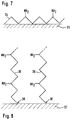
- Fig. 7 shows a plasma polymer 34 with free amino (-NH 2 ) groups (at every 2 nd carbon atom in the polymer chain) on the surface 35 of an intravascular probe obtained with the plasma polymerization technique.
- Fig. 8 shows a plasma polymer 34 with free amino (-NH 2 ) groups (at every 2 nd carbon atom in the polymer chain) on the surface 35 of an intravascular probe obtained with the plasma polymerization technique.
- the result of the plasma grafting technique is depicted in Fig. 8.
- the ends of the plasma grafted chains 36 adhere to the surface 37, as depicted by reference number 38. This is a covalent bonding which provides better contact between polymer and surface and reduces the probability of detachment of the polymer.
- the polymer chains in the environment of Fig. 8 are generally shorter.
- a pressure-tight, electrically shielded chamber 39 contains a shelf or rack 40 for pinning up of intravascular probes.
- the front opening 41 may be closed by a suitable door (not shown).
- a pump 42 is used to obtain the required low pressure. It is connected via tube 43 to back wall 44 of chamber 39. The source of radiation is depicted as 45.
- Three openings 46, 47 and 48 are provided as inlets for oxygen, argon and allylamine (or polyacrylic acid), respectively. These openings are connected via tubes 49, 50 and 51 to respective containers 52, 53 and 54 holding these gases, or volatile liquids.
Landscapes
- Health & Medical Sciences (AREA)
- Hematology (AREA)
- Surgery (AREA)
- Epidemiology (AREA)
- Life Sciences & Earth Sciences (AREA)
- Animal Behavior & Ethology (AREA)
- General Health & Medical Sciences (AREA)
- Public Health (AREA)
- Veterinary Medicine (AREA)
- Chemical & Material Sciences (AREA)
- Engineering & Computer Science (AREA)
- Materials Engineering (AREA)
- Materials For Medical Uses (AREA)
Claims (14)
- Verfahren zum Aufbringen einer antithrombogenen biologischen Bedeckung auf die Oberfläche eines medizinischen Gerätes, das für einen Blutkontakt vorgesehen ist, gekennzeichnet durch die Schritte:(1.1) Aussetzen des medizinischen Gerätes einem chemischen Agens bestehend aus(1.1.1) Monomermolekülen die 1) entweder zwei Kohlenstoffatome mit Trippelbindung untereinander oder 2) zumindest zwei Kohlenstoffatome mit Doppelbindung untereinander enthalten, wobei die Monomermoleküle zusätzliche chemisch aktive funktionale Gruppen, geeignet zum Reagieren mit der antithrombogenen biologischen Bedeckung, aufweisen, oder aus(1.1.2) Monomermolekülen die 1) entweder zwei Kohlenstoffatome mit Trippelbindung untereinander oder 2) zumindest zwei Kohlenstoffatome mit Doppelbindung untereinander enthalten, wobei die Monomermoleküle mit einer Substanz gemischt sind, die, unter dem Einfluß elektromagnetischer Bestrahlung, eine chemisch aktive funktionale Gruppe bilden, die chemisch an den Monomer bindet und geeignet ist, um mit der antithrombogenen biologischen Bedeckung zu reagieren,wobei das chemische Agens zumindest in dessen gasförmigem Zustand anwesend ist,(1.2) Einstrahlen elektromagnetischer Wellen, insbesondere im Hochfrequenzbereich, in das chemische Agens und/oder auf die Oberfläche des medizinischen Gerätes bis die Moleküle in dem chemischen Agens einen funktionalen Polymer auf der Oberfläche des medizinischen Gerätes konstituieren,(1.3) Aufbringen der biologischen Bedeckung auf die Oberfläche des medizinischen Gerätes, wobei eine kovalente Bindung zwischen der chemisch aktiven funktionalen Gruppe und der antithrombogenen biologischen Bedeckung hergestellt wird.
- Verfahren zum Aufbringen einer antithrombogenen biologischen Bedeckung auf die Oberfläche eines medizinischen Gerätes, das für einen Blutkontakt vorgesehen ist, gekennzeichnet durch die Schritte:(2.1) Aussetzen des medizinischen Gerätes einem Inertgas,(2.2) Einstrahlen elektromagnetischer Wellen, insbesondere im Hochfrequenzbereich, in das Inertgas und/oder auf die Oberfläche des medizinischen Gerätes,(2.3) Aussetzen des medizinischen Gerätes einem chemischen Agens bestehend aus(2.3.1) Monomermolekülen die 1) entweder zwei Kohlenstoffatome mit Trippelbindung untereinander oder 2) zumindest zwei Kohlenstoffatome mit Doppelbindung untereinander enthalten, wobei die Monomermoleküle zusätzliche chemisch aktive funktionale Gruppen, geeignet zum Reagieren mit der antithrombogenen biologischen Bedeckung, aufweisen, oder aus(2.3.2) Monomermolekülen die 1) entweder zwei Kohlenstoffatome mit Trippelbindung untereinander oder 2) zumindest zwei Kohlenstoffatome mit Doppelbindung untereinander enthalten, wobei die Monomermoleküle mit einer Substanz gemischt werden, die, unter dem Einfluß von Ladungsträgern, die während Schritt (2.2) erzeugt werden, eine chemisch aktive funktionale Gruppe bildet, die sich chemisch an den Monomer bindet und die geeignet ist, um mit der antithrombogenen biologischen Bedeckung zu reagieren,
wobei das chemische Agens zumindest in dessen gasförmigem Zustand anwesend ist, bis die Moleküle des chemischen Agens ein funktionales Polymer auf der Oberfläche des chemischen Gerätes darstellen,(2.4) Aufbringen der biologischen Bedeckung auf die Oberfläche des medizinischen Gerätes, wobei eine kovalente Bindung zwischen der chemisch aktiven funktionalen Gruppe und der antithrombogenen biologischen Bedeckung hergestellt wird. - Verfahren entsprechend einem der vorangegangenen Ansprüche, dadurch gekennzeichnet, daß das chemische Agens in einer geschlossenen Kammer (39) enthalten ist, die auch das medizinische Gerät enthält.
- Verfahren entsprechend Anspruch 3, dadurch gekennzeichnet, daß die Kammer (39) druckdicht ist und daß ein Druck unterhalb des Atmosphärendrucks der Kammer angewandt wird.
- Verfahren entsprechend Anspruch 4, dadurch gekennzeichnet, daß der Druck in der Kammer (39) annähernd ein Vakuum ist, insbesondere im Bereich von 10-5 bar bis 10-2 bar und spezieller im Bereich von 10-4 bar bis 10-3 bar.
- Verfahren entsprechend einem der vorangegangenen Ansprüche, dadurch gekennzeichnet, daß die chemisch aktive funktionale Gruppe in den Molekülen des chemischen Agens eine Aminogruppe ist.
- Verfahren entsprechend Anspruch 6, dadurch gekennzeichnet, daß das chemische Agens ein Allylamin, ein 4-Amino-1-Buten oder irgendein anderes Olefin mit einer zusätzlichen Aminogruppe, oder eine Kombination aus Olefin und Ammoniumhydroxid ist.
- Verfahren entsprechend einem der Ansprüche 1 bis 5, dadurch gekennzeichnet, daß die chemisch aktive funktionale Gruppe in den Molekülen des chemischen Agens eine Carboxylgruppe ist.
- Verfahren entsprechend Anspruch 8, dadurch gekennzeichnet, daß das chemische Agens aus der Gruppe der Carboxylsäuren ausgewählt wird, insbesondere Acrylsäure, Butensäure oder Pentensäure.
- Verfahren entsprechend einem der Ansprüche 1-5, dadurch gekennzeichnet, daß die chemisch aktive funktionale Gruppe in den Molekülen des chemischen Agens eine OH-Gruppe ist.
- Verfahren entsprechend Anspruch 10, dadurch gekennzeichnet, daß das chemische Agens ein Allylalkohol ist.
- Verfahren entsprechend einem der vorangegangenen Ansprüche, gekennzeichnet durch die zusätzlichen Schritte:(12.1) Aussetzen des medizinischen Gerätes einem chemisch aktiven Gas, insbesondere Sauerstoff,(12.2) Einstrahlen elektromagnetischer Wellen in das chemisch aktive Gas und/oder auf die Oberfläche des medizinischen Gerätes, bis die Oberfläche des medizinischen Gerätes im wesentlichen sauber von Unreinheiten ist,worin die Schritte vor dem Aussetzen des medizinischen Gerätes dem chemischen Agens durchgeführt werden.
- Verfahren entsprechend einem der vorangegangenen Ansprüche, gekennzeichnet durch den Schritt des Auftragens der antithrombogenen biologischen Bedeckung auf die polymerisierte Oberfläche des medizinischen Gerätes mittels einer Veresterung, einer Amidsäurebildung, einer Aminsäurebildung oder einer Verätherung.
- Verfahren entsprechend einem der vorangegangenen Ansprüche, dadurch gekennzeichnet, daß das medizinische Gerät ein intravaskularer Blutgassensor ist.
Priority Applications (4)
| Application Number | Priority Date | Filing Date | Title |
|---|---|---|---|
| DE69125828T DE69125828T2 (de) | 1991-05-21 | 1991-05-21 | Verfahren zur Vorbehandlung der Oberfläche eines medizinischen Artikels |
| EP91108146A EP0519087B1 (de) | 1991-05-21 | 1991-05-21 | Verfahren zur Vorbehandlung der Oberfläche eines medizinischen Artikels |
| US07/861,325 US5451428A (en) | 1991-05-21 | 1992-03-31 | Method for pretreating the surface of a medical device |
| JP4154516A JPH05220217A (ja) | 1991-05-21 | 1992-05-21 | 医療デバイスの表面処理方法及びその装置 |
Applications Claiming Priority (1)
| Application Number | Priority Date | Filing Date | Title |
|---|---|---|---|
| EP91108146A EP0519087B1 (de) | 1991-05-21 | 1991-05-21 | Verfahren zur Vorbehandlung der Oberfläche eines medizinischen Artikels |
Publications (2)
| Publication Number | Publication Date |
|---|---|
| EP0519087A1 EP0519087A1 (de) | 1992-12-23 |
| EP0519087B1 true EP0519087B1 (de) | 1997-04-23 |
Family
ID=8206746
Family Applications (1)
| Application Number | Title | Priority Date | Filing Date |
|---|---|---|---|
| EP91108146A Expired - Lifetime EP0519087B1 (de) | 1991-05-21 | 1991-05-21 | Verfahren zur Vorbehandlung der Oberfläche eines medizinischen Artikels |
Country Status (4)
| Country | Link |
|---|---|
| US (1) | US5451428A (de) |
| EP (1) | EP0519087B1 (de) |
| JP (1) | JPH05220217A (de) |
| DE (1) | DE69125828T2 (de) |
Cited By (1)
| Publication number | Priority date | Publication date | Assignee | Title |
|---|---|---|---|---|
| US6926690B2 (en) | 1998-09-10 | 2005-08-09 | Percardia, Inc. | Transmyocardial shunt and its attachment mechanism, for left ventricular revascularization |
Families Citing this family (55)
| Publication number | Priority date | Publication date | Assignee | Title |
|---|---|---|---|---|
| US5344455A (en) * | 1992-10-30 | 1994-09-06 | Medtronic, Inc. | Graft polymer articles having bioactive surfaces |
| WO1996008211A2 (en) * | 1994-09-09 | 1996-03-21 | Surface Engineering Technologies, Division Of Innerdyne, Inc. | Plasma grafting methods and compounds |
| DE19604173C2 (de) * | 1996-02-06 | 2000-07-06 | Hartwig Hoecker | Verfahren zur Erzeugung antithrombogener Oberflächen auf extrakorporal und/oder intrakorporal zu verwendenden medizinischen Gegenständen |
| US6329024B1 (en) | 1996-04-16 | 2001-12-11 | Board Of Regents, The University Of Texas System | Method for depositing a coating comprising pulsed plasma polymerization of a macrocycle |
| US5876753A (en) * | 1996-04-16 | 1999-03-02 | Board Of Regents, The University Of Texas System | Molecular tailoring of surfaces |
| US6482531B1 (en) | 1996-04-16 | 2002-11-19 | Board Of Regents, The University Of Texas System | Non-fouling, wettable coated devices |
| US6306165B1 (en) | 1996-09-13 | 2001-10-23 | Meadox Medicals | ePTFE small caliber vascular grafts with significant patency enhancement via a surface coating which contains covalently bonded heparin |
| CA2294872A1 (en) * | 1997-06-24 | 1998-12-30 | Schering Aktiengesellschaft | Stents that are coated with fluoroalkyl groups, processes for their production and their use for restenosis prophylaxis |
| DE19730296A1 (de) * | 1997-07-15 | 1999-01-21 | Medic Medizintechnik Lothar Se | Verfahren und Vorrichtung zur Steigerung der Hämokompatibilität von Implantaten |
| GB9902823D0 (en) | 1998-12-23 | 1999-03-31 | Dow Corning Sa | Biocompatible coatings |
| US6273901B1 (en) | 1999-08-10 | 2001-08-14 | Scimed Life Systems, Inc. | Thrombosis filter having a surface treatment |
| US6790228B2 (en) * | 1999-12-23 | 2004-09-14 | Advanced Cardiovascular Systems, Inc. | Coating for implantable devices and a method of forming the same |
| AU2001232802A1 (en) * | 2000-01-14 | 2001-07-24 | Charles C. Carney | Method for plasma charging a probe |
| US6724608B2 (en) * | 2000-01-14 | 2004-04-20 | Paul Hensley | Method for plasma charging a probe |
| US20040209303A1 (en) | 2000-10-03 | 2004-10-21 | Martin Mark T. | Methods and compositions for directed microwave chemistry |
| WO2002029076A1 (en) * | 2000-10-03 | 2002-04-11 | Mirari Biosciences, Inc. | Methods and compositions for directed microwave chemistry |
| US7348182B2 (en) * | 2000-10-03 | 2008-03-25 | Mirari Biosciences, Inc. | Directed microwave chemistry |
| WO2002070032A1 (en) * | 2001-03-02 | 2002-09-12 | UNIVERSITé LAVAL | Plasma surface graft process for reducing thrombogenicity |
| US7396582B2 (en) * | 2001-04-06 | 2008-07-08 | Advanced Cardiovascular Systems, Inc. | Medical device chemically modified by plasma polymerization |
| US6977138B2 (en) | 2001-07-24 | 2005-12-20 | Massachusetts Institute Of Technology | Reactive polymer coatings |
| US7682669B1 (en) * | 2001-07-30 | 2010-03-23 | Advanced Cardiovascular Systems, Inc. | Methods for covalently immobilizing anti-thrombogenic material into a coating on a medical device |
| AU2003211465A1 (en) * | 2002-02-19 | 2003-09-09 | Kazuhiko Ishihara | Artificial joint member made of polymeric material |
| WO2003075790A2 (en) * | 2002-03-08 | 2003-09-18 | The University Of Texas Health Science Center At San Antonio | Gas-plasma treatment of implants |
| GB0225197D0 (en) * | 2002-10-30 | 2002-12-11 | Univ Sheffield | Surface |
| US20060272675A1 (en) * | 2005-06-02 | 2006-12-07 | Cerionx, Inc. | Method and apparatus for cleaning and surface conditioning objects using plasma |
| US20060272674A1 (en) * | 2005-06-02 | 2006-12-07 | Cerionx, Inc. | Method and apparatus for cleaning and surface conditioning objects using plasma |
| CA2528194A1 (en) * | 2003-06-16 | 2005-01-06 | Cerionx, Inc. | Atmospheric pressure non-thermal plasma device to clean and sterilize the surface of probes, cannulas, pin tools, pipettes and spray heads |
| US8366871B2 (en) * | 2003-06-16 | 2013-02-05 | Ionfield Holdings, Llc | Method and apparatus for cleaning and surface conditioning objects using plasma |
| US8092644B2 (en) * | 2003-06-16 | 2012-01-10 | Ionfield Systems, Llc | Method and apparatus for cleaning and surface conditioning objects using plasma |
| US20060162740A1 (en) * | 2005-01-21 | 2006-07-27 | Cerionx, Inc. | Method and apparatus for cleaning and surface conditioning objects using non-equilibrium atmospheric pressure plasma |
| US8092643B2 (en) * | 2003-06-16 | 2012-01-10 | Ionfield Systems, Llc | Method and apparatus for cleaning and surface conditioning objects using plasma |
| US20060162741A1 (en) * | 2005-01-26 | 2006-07-27 | Cerionx, Inc. | Method and apparatus for cleaning and surface conditioning objects with plasma |
| US7335185B2 (en) * | 2003-07-18 | 2008-02-26 | Boston Scientific Scimed, Inc. | Protective coatings for medical devices |
| NZ546981A (en) * | 2003-11-07 | 2009-10-30 | Nobil Bio Ricerche Srl | Method for preparing drug eluting medical devices and devices obtained therefrom |
| AU2005204981B2 (en) * | 2004-01-19 | 2010-03-04 | University Of South Australia | Bioactive coating of biomedical implants |
| US7674251B2 (en) * | 2004-04-08 | 2010-03-09 | Boston Scientific Scimed, Inc. | Medical devices including aerated adhesive bonds and methods of forming the same |
| EP1867298A4 (de) * | 2005-04-07 | 2014-10-29 | Terumo Corp | Arznei-eluierendes stentsystem und verfahren zu seiner herstellung |
| US20060237030A1 (en) * | 2005-04-22 | 2006-10-26 | Cerionx, Inc. | Method and apparatus for cleaning and surface conditioning objects with plasma |
| US8574259B2 (en) * | 2005-05-10 | 2013-11-05 | Lifescreen Sciences Llc | Intravascular filter with drug reservoir |
| EP1948750A1 (de) * | 2005-11-16 | 2008-07-30 | FUJIFILM Corporation | Struktur mit hydrophiler oberfläche |
| JP5094081B2 (ja) * | 2005-11-17 | 2012-12-12 | 富士フイルム株式会社 | 親水性部材及びその製造方法 |
| US7752797B1 (en) * | 2006-02-08 | 2010-07-13 | Swan Richard E | Sling swivel with integrated screwdriver |
| US7909928B2 (en) | 2006-03-24 | 2011-03-22 | The Regents Of The University Of Michigan | Reactive coatings for regioselective surface modification |
| US7947148B2 (en) | 2006-06-01 | 2011-05-24 | The Regents Of The University Of Michigan | Dry adhesion bonding |
| US8012591B2 (en) * | 2006-09-21 | 2011-09-06 | Fujifilm Corporation | Hydrophilic composition and hydrophilic member |
| US8399047B2 (en) | 2007-03-22 | 2013-03-19 | The Regents Of The Univeristy Of Michigan | Multifunctional CVD coatings |
| JP2008238711A (ja) * | 2007-03-28 | 2008-10-09 | Fujifilm Corp | 親水性部材及び下塗り組成物 |
| US20090029179A1 (en) * | 2007-05-14 | 2009-01-29 | Fujifilm Corporation | Two-liquid composition, hydrophilic composition and hydrophilic member |
| WO2009146432A1 (en) * | 2008-05-30 | 2009-12-03 | Colorado State University Research Foundation | Plasma-based chemical source device and method of use thereof |
| EP2364176A1 (de) * | 2008-11-14 | 2011-09-14 | Cardiac Pacemakers, Inc. | Kaltplasmabindung von polymerschläuchen in implantierbaren medizinprodukten |
| US8808365B2 (en) * | 2009-01-07 | 2014-08-19 | Martin Kean Chong Ng | Chemically and biologically modified medical devices |
| US20120156433A1 (en) | 2010-12-21 | 2012-06-21 | Natarajan Sriram N | Silicone polymer substrates having improved biological response from hkdcs |
| US20120156780A1 (en) | 2010-12-21 | 2012-06-21 | Cooper Kevin L | Polymer Substrates Having Improved Biological Response From HKDCS |
| US20120321776A1 (en) | 2011-06-17 | 2012-12-20 | Robert Vetrecin | Process for in situ plasma polymerization of silicone coatings for surgical needles |
| EP3106128B1 (de) * | 2014-02-12 | 2020-12-02 | Toray Industries, Inc. | Künstliches blutgefäss |
Family Cites Families (24)
| Publication number | Priority date | Publication date | Assignee | Title |
|---|---|---|---|---|
| US4072928A (en) * | 1975-10-10 | 1978-02-07 | Sangamo Weston, Inc. | Industrial system for inspecting and identifying workpieces |
| US4193138A (en) * | 1976-08-20 | 1980-03-18 | Sumitomo Electric Industries, Ltd. | Composite structure vascular prostheses |
| US4326532A (en) * | 1980-10-06 | 1982-04-27 | Minnesota Mining And Manufacturing Company | Antithrombogenic articles |
| SE8200751L (sv) * | 1982-02-09 | 1983-08-10 | Olle Larm | Forfarande for kovalent koppling for framstellning av konjugat och hervid erhallna produkter |
| US5002582A (en) * | 1982-09-29 | 1991-03-26 | Bio-Metric Systems, Inc. | Preparation of polymeric surfaces via covalently attaching polymers |
| US5258041A (en) * | 1982-09-29 | 1993-11-02 | Bio-Metric Systems, Inc. | Method of biomolecule attachment to hydrophobic surfaces |
| CA1215676A (en) * | 1983-04-27 | 1986-12-23 | Terry S. Dunn | Heparinization of plasma treated substrates |
| US5034265A (en) * | 1983-08-01 | 1991-07-23 | Washington Research Foundation | Plasma gas discharge treatment for improving the compatibility of biomaterials |
| JPS60227763A (ja) * | 1984-04-27 | 1985-11-13 | 筏 義人 | 抗血栓性医用材料 |
| CH665954A5 (fr) * | 1985-07-08 | 1988-06-30 | Battelle Memorial Institute | Substrat dont la surface presente une activite antithrombogenique. |
| US4919659A (en) * | 1985-12-16 | 1990-04-24 | The Board Of Regents For The University Of Washington | Radio frequency plasma deposited polymers that enhance cell growth |
| US4897433A (en) * | 1986-12-08 | 1990-01-30 | Japan Atomic Energy Research Inst. | Process for producing an anti-thrombogenic material by graft polymerization |
| NL8701337A (nl) * | 1987-06-09 | 1989-01-02 | Sentron V O F | Substraat voorzien van een bloedcompatibel oppervlak, verkregen door koppeling aan het oppervlak van een fysiologisch aktieve stof met remmende invloed op de vorming van bloedstolsels en/of in staat om gevormde bloedstolsels af te breken, alsmede werkwijze ter vervaardiging van het substraat. |
| US4921723A (en) * | 1987-10-16 | 1990-05-01 | The Curators Of The University Of Missouri | Process for applying a composite insulative coating to a substrate |
| JPH01300958A (ja) * | 1988-05-31 | 1989-12-05 | Canon Inc | 表面機能性膜を有する眼内レンズ |
| JPH04501964A (ja) * | 1988-06-07 | 1992-04-09 | バイオゴールド・インコーポレイテツド | 生体適合性の人工器官の製造方法 |
| US4846101A (en) * | 1988-07-01 | 1989-07-11 | Becton, Dickinson And Company | Apparatus for plasma treatment of small diameter tubes |
| JPH064713B2 (ja) * | 1988-07-22 | 1994-01-19 | テルモ株式会社 | 生体適合性材料 |
| US5053048A (en) * | 1988-09-22 | 1991-10-01 | Cordis Corporation | Thromboresistant coating |
| US5080924A (en) * | 1989-04-24 | 1992-01-14 | Drexel University | Method of making biocompatible, surface modified materials |
| JP2930329B2 (ja) * | 1989-09-28 | 1999-08-03 | ソニー株式会社 | 抗血栓性材料 |
| NL194941C (nl) * | 1990-02-15 | 2003-08-04 | Cordis Corp | Werkwijze voor het aanbrengen van een fysiologisch actieve verbinding op een substraatoppervlak. |
| US5244654A (en) * | 1990-11-08 | 1993-09-14 | Cordis Corporation | Radiofrequency plasma biocompatibility treatment of inside surfaces of medical tubing and the like |
| US5246451A (en) * | 1991-04-30 | 1993-09-21 | Medtronic, Inc. | Vascular prosthesis and method |
-
1991
- 1991-05-21 EP EP91108146A patent/EP0519087B1/de not_active Expired - Lifetime
- 1991-05-21 DE DE69125828T patent/DE69125828T2/de not_active Expired - Fee Related
-
1992
- 1992-03-31 US US07/861,325 patent/US5451428A/en not_active Expired - Fee Related
- 1992-05-21 JP JP4154516A patent/JPH05220217A/ja active Pending
Cited By (1)
| Publication number | Priority date | Publication date | Assignee | Title |
|---|---|---|---|---|
| US6926690B2 (en) | 1998-09-10 | 2005-08-09 | Percardia, Inc. | Transmyocardial shunt and its attachment mechanism, for left ventricular revascularization |
Also Published As
| Publication number | Publication date |
|---|---|
| DE69125828D1 (de) | 1997-05-28 |
| DE69125828T2 (de) | 1997-07-31 |
| EP0519087A1 (de) | 1992-12-23 |
| US5451428A (en) | 1995-09-19 |
| JPH05220217A (ja) | 1993-08-31 |
Similar Documents
| Publication | Publication Date | Title |
|---|---|---|
| EP0519087B1 (de) | Verfahren zur Vorbehandlung der Oberfläche eines medizinischen Artikels | |
| US5914115A (en) | Biocompatible coating, medical device using the same and methods | |
| CA2293266C (en) | Treating metal surfaces to enhance bio-compatibility and/or physical characteristics | |
| EP1368075B1 (de) | Plasma oberflächen-pfropfprozess zur thrombogenitäts-reduzierung | |
| US5262451A (en) | Multifunctional thrombo-resistant coatings and methods of manufacture | |
| AU2002241676B2 (en) | Composite stent with polymeric covering and bioactive coating | |
| EP0947205A2 (de) | Verfahren zur Herstellung von biokompatiblen medizinischen Erzeugnissen | |
| JPH0145373B2 (de) | ||
| JPH05504902A (ja) | ガス透過性耐血栓形成性被覆剤および製造方法 | |
| EP1189553A1 (de) | Ballonexpandierbarer stent | |
| US5681657A (en) | Biocompatible porous hollow fiber and method of manufacture and use thereof | |
| JP2005537097A (ja) | デリバリーシステムのための保持コーティング | |
| EP0641226A1 (de) | Polymerbeschichtung. | |
| US20050244456A1 (en) | Surface coating comprising bioactive compound | |
| WO2006050110A2 (en) | Pro-fibrotic coatings comprising collagen for medical implants | |
| Mantovani et al. | Ammonia RF-plasma treatment of tubular ePTFE vascular prostheses | |
| CN114522278A (zh) | 一种长效抗凝血涂层及其制备方法 | |
| JP2002517285A (ja) | 生体適合性表面の製造方法 | |
| CA2202750A1 (en) | Biocompatible coating, medical device using the same and methods | |
| JPS6099259A (ja) | バイオマテリアルの生物適合性を改善するプラズマガス投射処理 |
Legal Events
| Date | Code | Title | Description |
|---|---|---|---|
| PUAI | Public reference made under article 153(3) epc to a published international application that has entered the european phase |
Free format text: ORIGINAL CODE: 0009012 |
|
| 17P | Request for examination filed |
Effective date: 19920220 |
|
| AK | Designated contracting states |
Kind code of ref document: A1 Designated state(s): DE FR GB |
|
| 17Q | First examination report despatched |
Effective date: 19931022 |
|
| GRAG | Despatch of communication of intention to grant |
Free format text: ORIGINAL CODE: EPIDOS AGRA |
|
| GRAH | Despatch of communication of intention to grant a patent |
Free format text: ORIGINAL CODE: EPIDOS IGRA |
|
| GRAH | Despatch of communication of intention to grant a patent |
Free format text: ORIGINAL CODE: EPIDOS IGRA |
|
| GRAH | Despatch of communication of intention to grant a patent |
Free format text: ORIGINAL CODE: EPIDOS IGRA |
|
| GRAH | Despatch of communication of intention to grant a patent |
Free format text: ORIGINAL CODE: EPIDOS IGRA |
|
| GRAA | (expected) grant |
Free format text: ORIGINAL CODE: 0009210 |
|
| PGFP | Annual fee paid to national office [announced via postgrant information from national office to epo] |
Ref country code: FR Payment date: 19970421 Year of fee payment: 7 |
|
| AK | Designated contracting states |
Kind code of ref document: B1 Designated state(s): DE FR GB |
|
| PGFP | Annual fee paid to national office [announced via postgrant information from national office to epo] |
Ref country code: GB Payment date: 19970425 Year of fee payment: 7 |
|
| PGFP | Annual fee paid to national office [announced via postgrant information from national office to epo] |
Ref country code: DE Payment date: 19970428 Year of fee payment: 7 |
|
| REF | Corresponds to: |
Ref document number: 69125828 Country of ref document: DE Date of ref document: 19970528 |
|
| ET | Fr: translation filed | ||
| PLBE | No opposition filed within time limit |
Free format text: ORIGINAL CODE: 0009261 |
|
| STAA | Information on the status of an ep patent application or granted ep patent |
Free format text: STATUS: NO OPPOSITION FILED WITHIN TIME LIMIT |
|
| 26N | No opposition filed | ||
| PG25 | Lapsed in a contracting state [announced via postgrant information from national office to epo] |
Ref country code: GB Free format text: LAPSE BECAUSE OF NON-PAYMENT OF DUE FEES Effective date: 19980521 |
|
| PG25 | Lapsed in a contracting state [announced via postgrant information from national office to epo] |
Ref country code: FR Free format text: LAPSE BECAUSE OF NON-PAYMENT OF DUE FEES Effective date: 19980531 |
|
| GBPC | Gb: european patent ceased through non-payment of renewal fee |
Effective date: 19980521 |
|
| PG25 | Lapsed in a contracting state [announced via postgrant information from national office to epo] |
Ref country code: DE Free format text: LAPSE BECAUSE OF NON-PAYMENT OF DUE FEES Effective date: 19990302 |
|
| REG | Reference to a national code |
Ref country code: FR Ref legal event code: ST |