EP0516182A1 - Dispositif d'inclinaison de doigt pour alimenteur de transfert - Google Patents
Dispositif d'inclinaison de doigt pour alimenteur de transfert Download PDFInfo
- Publication number
- EP0516182A1 EP0516182A1 EP92112144A EP92112144A EP0516182A1 EP 0516182 A1 EP0516182 A1 EP 0516182A1 EP 92112144 A EP92112144 A EP 92112144A EP 92112144 A EP92112144 A EP 92112144A EP 0516182 A1 EP0516182 A1 EP 0516182A1
- Authority
- EP
- European Patent Office
- Prior art keywords
- finger
- angle
- shaft portion
- angle defining
- lever
- Prior art date
- Legal status (The legal status is an assumption and is not a legal conclusion. Google has not performed a legal analysis and makes no representation as to the accuracy of the status listed.)
- Withdrawn
Links
Images


Classifications
-
- B—PERFORMING OPERATIONS; TRANSPORTING
- B21—MECHANICAL METAL-WORKING WITHOUT ESSENTIALLY REMOVING MATERIAL; PUNCHING METAL
- B21D—WORKING OR PROCESSING OF SHEET METAL OR METAL TUBES, RODS OR PROFILES WITHOUT ESSENTIALLY REMOVING MATERIAL; PUNCHING METAL
- B21D43/00—Feeding, positioning or storing devices combined with, or arranged in, or specially adapted for use in connection with, apparatus for working or processing sheet metal, metal tubes or metal profiles; Associations therewith of cutting devices
- B21D43/02—Advancing work in relation to the stroke of the die or tool
- B21D43/04—Advancing work in relation to the stroke of the die or tool by means in mechanical engagement with the work
- B21D43/05—Advancing work in relation to the stroke of the die or tool by means in mechanical engagement with the work specially adapted for multi-stage presses
- B21D43/055—Devices comprising a pair of longitudinally and laterally movable parallel transfer bars
Definitions
- the present invention relates to a finger tilting apparatus for a transfer feeder which is employable for a transfer press or the like machine.
- a transfer feeder equipped on a transfer press is provided with a pair of feed bars arranged in parallel with each other to perform three-dimensional movement by cams, levers or the like members so that a work is clamped by fingers situated at opposing positions of the feed bars so as to allow the work to be transferred between adjacent working stations in a press housing.
- a lifting operation can be performed only via a straight track with the result that a lift stroke is unavoidably elongated and thereby it becomes difficult to reduce the time required for transferring the work.
- JP-U-190,222/1975 discloses that fingers are supported to turn relative to feed bars via their shaft portions and a mechanism for rotating the shaft portions is provided to tilt the fingers relative to the feed bars. According to this proposal, a work is correctly placed in a die by adequately tilting the fingers in consideration of the shape of the die and reduction of a lift stroke is achieved by simultaneously performing a lifting operation and a tilting operation.
- such a type of conventional finger tilting apparatus includes a plate adapted to be turned in operative association with the shaft portion of a finger, an elongated hole formed in the plate and a defining pin held on a vertical plate firmly secured to a feed bar and slidably fitted in the elongated hole so that a tilt angle of the finger is defined by allowing the defining pin to come in contact with opposite end faces of the elongated hole.
- a lifting operation and a tilting operation can not simultaneously be performed when the work is to be lifted up (with the exception of a case where the finger is restored to its initial angle).
- the tilt angle of the finger is to be changed, this is achieved by selectively fitting the defining pin into one of a plurality of different elongated holes preformed in the plate. Consequently, an attitude of the work can not be changed to an angle rather other than the tilt angles defined by the elongated holes. Thus, the requirement for changing the tilt angle in response to change or modification of the specification given to the work can not be met quickly.
- DE-A-3 236 107 discloses an apparatus for turning an article during movement along a transport path.
- This apparatus has two parallel feed bars which are moved reciprocatingly and which have grippers to grip a work piece from opposite sides. Two grippers being in mutual alignment are turning around 180° around their common axis. At least one of the grippers is connected to a rotating lever which is guided in a guide rail running in parallel to the feed bars.
- the guide rail has a guide notch which is shaped so that the grippers are turned around their axis by 180° upon the linear movement of the feed bars. However, there are not tilting fingers for changing the attitude of the work piece.
- An object of the present invention is to provide a finger tilting apparatus for a transfer feeder which assures that a requirement for changing the tilt angle in response to change or modification of the specification given to a work can be met quickly.
- the invention is defined by the features of claim 1.
- At least one of the angle defining lever, the engagement lever and the guide member is continuously displaced to change an angle of rotation of the shaft portion of the finger.
- the angle of rotation of the shaft portion of the finger can be defined to an arbitrary angel. Consequently, a requirement for changing a tilt angle in response to change or modification of the specification given to a work can be met quickly.
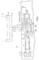
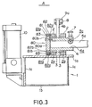
- Figs. 1 to 3 show a finger tilting apparatus for a transfer feeder in accordance with a first embodiment of the present invention, respectively, wherein Fig. 1 is a plan view of the apparatus, Fig. 2 is a front view of the apparatus and Fig. 3 is a sectional side view of the apparatus, Fig. 4 is a front view schematically illustrating essential components constituting a finger tilting apparatus for a transfer feeder in accordance with a second embodiment of the present invention, Fig. 5 is a front view schematically illustrating essential components constituting a finger tilting apparatus for a transfer feeder in accordance with a third embodiment of the present invention, Fig.
- FIG. 6 is a side view schematically illustrating essential components constituting a finger tilting apparatus for a transfer finger in accordance with a fourth embodiment of the present invention
- Fig. 7 is a side view schematically illustrating essential components constituting a finder tilting apparatus for a transfer feeder in accordance with a fifth embodiment of the present invention
- Fig. 8 is a front view schematically illustrating essential components constituting a finger tilting apparatus for a transfer feeder in accordance with a sixth embodiment of the present invention
- Fig. 9 is a side view schematically illustrating essential components constituting a finger tilting apparatus in accordance with a seventh embodiment of the present invention
- Fig. 10 is a side view schematically illustrating essential components constituting a finger tilting apparatus for a transfer feeder in accordance with an eighth embodiment of the present invention.
- Figs. 1 to 3 diagramatically illustrate a finger tilting apparatus for a transfer feeder in accordance with a first embodiment of the present invention, respectively.
- the transfer feeder as exemplified in the drawings includes a pair of feed bars (not clearly shown in the drawings) arranged n parallel with each other to perform their three-dimensional movement in operative association with cams, lever and other members so that fingers are located opposite to each other at plural opposing positions assumed by the feed bars by means of a plurality of finger tilting apparatuses. Since the finger tilting apparatuses are identical to each other in structure, only one of them will typically be described in more details in the following.
- the feed bar 1 is constructed in a long column-shaped structure having a rectangular cross-sectional shape which comprises an upper plate 1a, a lower plate 1b and a pair of side plates 1c by way of which the upper plate 1a and the lower plate 1b are connected to each other, and a pair of brackets 2 are fixedly mounted on the upper plates 1b.
- the brackets 2 are disposed at positions offset from the longitudinally extending center line of the feed bar 1 in the direction toward a position assumed by another feed bar which is not shown in the drawings (in the direction of an arrow mark A in the drawing).
- the direction toward a position where another feed bar is disposed is hereinafter referred to as "inward of the feed bar 1".
- brackets 2 are spaced from each other in the transverse direction of the feed bar 1, and bearing holes 2a are formed at the central positions on the brackets 2 in such a manner that their axial centers are located in alignment with each other in the transverse direction of the feed bar 1.
- a finger holding member 4 is rotatably inserted through the bearing holes 2a across the both brackets 2 while bushes 3 are interposed between the both brackets 2 and the finger holding member 4.
- opposite ends of the the finger holding member 4 are projected outward of the brackets 2 and one of the opposite ends located inside of the feed bar 1 is situated above the side end of the upper plate 1a.
- the finger holding member 4 is formed with a substantially square fitting hole 4a at its central part so that the shaft portion 5a of a finger 5 is removably fitted through the fitting hole 4a.
- the finger 5 includes clamp portions 5b for clamping a work 6, at the fore end of the shaft portion 5a having a substantially square cross-sectional shape.
- the finger 5 is operatively connected to the holding member 4 in such a manner that the clamp portions 5b are projected inward of the inner end of the finger holding member 4 on the feed bar 1.
- reference numeral 7 designates a stopper pin of which fore end comes in and out of the fitting hole 4a' of the finger holding member 4. Once the fore end of the stopper pin 7 is fitted into an engagement hole 5c on the shaft portion 5a of the finger 5, this inhibits the finger 5 from moving away from the finger holding member 4.
- the finger holding member 4 is provided with a turn lever 4b at a position between the pair of brackets 2.
- the turn lever 4b made integral with the finger holding member 4 extends in the radial direction from the outer periphery of the finger holding member 4, and the actuating rod 9a of a cylinder actuator 9 is pivotally connected to the fore end of the turn lever 4b via a pin 8.
- the cylinder actuator 9 is actuated by hydraulic pressure which has been converted from pneumatic pressure in air-hydro cylinders 10 as shown in Figs. 2 and 3.
- the cylinder actuator 9 is arranged in the longitudinal direction of the feed bar 1 and its bottom end is pivotally supported on the upper plate 1a of the feed bar 1 via a bracket 11 and a pin 12.
- the finger tilting apparatus is provided with a stop lever 19 at a certain position between the brackets 2 on the finger holding member 4.
- a roller 21 is rotatably supported at the fore end of the stop lever 19 via a pin 20.
- the finger tilting apparatus is provided with a rail member 22 at a certain position between the,brackets 2 on the upper plate 1a of the feed bar 1.
- the rail member 22 extends from a position outward of the brackets 2 to a position corresponding to the roller 21 of the stop lever 19 and a stopper member 23 is displaceably mounted on the rail member 22 at the last-mentioned position.
- the stopper member 23 has a stopper face 23a formed thereon and it is forwardly and backwardly displaced in the longitudinal direction of the feed bar 1 by actuating a thin walled-type cylinder actuator 24 firmly mounted on the upper plate 1a of the feed bar 1, while the stopper face 23a is directed upwardly.
- the finger tilting apparatus is provided with an angle defining member 80 at one end of the finger holding member 4 above the upper plate 1a of the feed bar 1.
- the angle defining member 80 includes a circular disc plate 80a having the same diameter as that of the finger holding member 4 and a lever portion 80b (serving as an angle defining lever) extending in the radial direction from the outer peripheral surface of the circular disc plate 80a so that it is firmly mounted on the finger holding member 4 while the center axis of the circular disc plate 80a is located in correct alignment with the center axis of the finger holding member 4.
- the finger tilting apparatus is provided with a pair of ring members 81 and 82 along the outer end surface of the bracket 2 situated on the outside of the feed bar 1.
- the ring members 81 and 82 are designed in an annular contour while having a same diameter, respectively. Further, they are formed with a plurality of arc-shaped elongate holes 81a and 82a at positions corresponding to each other so that they are rotatably attached to the bracket 2 by means of a plurality of bolts 83 inserted through the elongated holes 81a and 82a.
- the elongated holes 81a and 82a on the ring members 81 and 82, through which the bolts 83 are inserted, are formed in a coaxial relationship relative to the center axis of their annulation and this construction makes it possible that the ring members 81 and 82 are rotated relative to each other about the center axis of the finger holding member 4 by changing positions assumes by the eiongated holes 81a and 82a relative to the bolts 83.
- the ring members 81 and 82 are situated outward of the outer peripheral surface of the angle defining member 80, and inner peripheral surfaces 81b and 82b of the latter are located outward of a lever portion 80b of the angle defining member 80.
- the respective ring members 81 and 82 include engagement pieces 81c and 82c. The engagement pieces 81 and 82 are projected inward of the inner peripheral surfaces 81b and 82b toward their center axis and their fore ends are located in the vicinity of the outer peripheral surface of the circular disc plate 80a for the angle defining member 80.
- the finger tilting apparatus as constructed in the above-described manner, when the cylinder actuator 9 is actuated to displace the actuating rod 9a in forward and rearward directions, the finger holding member 4 is rotated via the turn lever 4b, and as the finger holding member 4 is rotated in that way, the lever portion 80b of the angle defining member 80 and the stop lever 19 are turned and the shaft portion 5a of the finger 5 operatively connected to the finger holding member 4 is rotated about its center axis.
- An initial angle of the shaft portion 5a of the finger and an angle of rotation of the same are defined by operative engagement of the lever portion 80b of the angle defining member 80 with the engagement pieces 81c and 82c of the ring members 81 and 82, and since the engagement pieces 81c and 82c can continuously be displaced to arbitrary positions by adequate rotation of the ring members 81 and 82, the shaft portion 5a of the finger 5 can be held at an arbitrary angle of rotation thereof. Accordingly, even in case where a tilt angle of the finger 5 is to be changed in accordance with a requirement for change or modification of the specification given to a work to be clamped, the requirement can be met quickly and easily.
- an angle of rotation of the shaft portion 5a of the finger 5 is changed by continuously displacing the engagement pieces 81c and 82c of the ring members 81 and 82 serving as a guide member in the direction of turning movement of the lever portion 80b of the angle defining member 80 serving as an angle. defining lever.
- an initial angle of the shaft portion 5a of the finger 5 and an angle of rotation of the same may be changed, e.g., by continuously displacing the guide member in the direction of extension of the angle defining lever to change a practical arm length of the latter or an initial angle of the shaft portion 5a of the finger 5 and an angle of rotation of the same may be changed by immovably holding the guide member, holding the angle defining lever so as to allow the angle defining lever to be displaced relative to the shaft portion 5a of the finger 5 in the direction of turning movement thereof and then continuously displacing the angle defining lever. It should be added that these changes or modifications are achieved with the same advantageous effects as those in the described embodiment.
- Fig. 4 schematically illustrates a finger tilting apparatus for a transfer feeder in accordance with a second embodiment of the present invention
- Fig. 5 likewise schematically illustrates a finger tilting apparatus for a transfer feeder in accordance with a third embodiment of the present invention.
- At least one of an angle defining lever 90; 91 and a guide member 92; 93 is formed with a contact surface 92a; 91a which is inclined by a certain angle in the direction of extension the angle defining lever 90; 91.
- This arrangement makes it possible that in addition to a manner of displacement in accordance with the first embodiment of the present invention as described above, an initial angle of the shaft portion 5a of the finger 5 and an angle of rotation of the same can arbitrarily be defined even in case where the angle defining lever 90; 91 is continuously displaced relative to the shaft portion 5a of the finger 5 in the direction of extension thereof (in the direction of arrow marks c ; d in the drawings).
- Fig. 6 schematically illustrates a finger tilting apparatus for a transfer feeder in accordance with a fourth embodiment of the present invention
- Fig. 7 likewise schematically illustrates a finger tilting apparatus for a transfer feeder in accordance with a fifth embodiment of the present invention.
- At least one of an angle defining lever 94; 95 and a guide member 96; 97 is formed with a contact surface 96a; 95a which is inclined by a certain angle in the direction outward of a plane of turning movement of the angle defining lever 94; 95.
- This arrangement makes it possible that in addition to a manner of displacement in accordance with the sixth embodiment, at least one of the angle defining lever 94; 95 and the guide member 96; 97 can continuously be displaced in the direction of inclination of the contact surface 96a; 95a (in the direction of arrow marks e ; f in the drawings) with the same advantageous effects as those in the preceding embodiments.
- FIG. 8 schematically illustrate essential components constituting a finger tilting apparatus for a transfer feeder in accordance with a sixth embodiment of the present invention.
- a different point of this embodiment from the first embodiment consists only in a structure for limiting turning movement of the angle defining lever.
- the angle defining lever 100 is formed with an elongated hole 100a extending in the direction of extension of the angledefining lever 100, and a roller 102 is arranged so as to slidably move along the elangated hole 100a via a pin 101.
- a guide member 103 is firmly mounted on the upper plate 104a of a feed bar 104 and has a cut-out 103a formed therein.
- the cut-out 103a includes flat taper surfaces 103b and 103c (serving as a contact surface) along upper and lower peripheral edges.
- an angle of rotation of the shaft portion of a finger is determined by allowing the roller 102 on the angle defining lever 100 to come in contact with the taper surface 103b or 103c, and moreover an initial angle of the shaft portion of the finger and an angle of rotation of the same are adequately changed by displacing the roller 102 along the elongated hole 100.
- an initial angle of the shaft portion (not shown) of the finger and an angle of rotation of the same are changed as required by allowing the roller 102 serving as an engagement member to be continuously displaced in the direction of extension of the angle defining lever 100.
- an initial angle of the shaft portion (not shown) of the finger and an angle of rotation of the same may be changed as required by arranging the roller 102 so as to move in the direction of turning movement of the angle defining lever 100 and then continuously displacing the roller 102.
- an initial angle of the shaft portion (not shown) of the finger and an angle of rotation of the same may be changed as required by immovably holding the roller 102 on the angle defining lever 100, arranging at least one of the angle defining lever 100 and the guide member 103 so as to move in the direction of extension of the angle defining lever 100 or in the direction of turning movement of the angle defining lever 100 and then continuously displacing the angle defining lever 100 or the guide member 103.
- an initial angle of the shaft portion (not shown) of the finger and an angle of rotation of the same can be changed as required, even in case where the taper surfaces 103b and 103c on the guide member 103 are arranged to extend in parallel with the upper plate 104a of the feed bar 104.
- Fig. 9 schematically illustrates a finger tilting apparatus for a transfer feeder in accordance with a seventh embodiment of the present invention
- Fig. 10 likewise schematically illustrates a finger tilting apparatus for a transfer feeder in accordance with an eighth embodiment of the present invention.
- At least one of a roller 110; 111 and a guide member 112; 113 is formed with a contact surface 112a; 111a which is inclined in the direction of projection of the roller 110; 111.
- This arrangement makes it possible that in addition to a manner of displacement in accordance with the sixth embodiment, an initial angle of the shaft portion (not shown) of a finger and an angle of rotation of the same can arbitrarily be determined, even in case where at least one of the angle defining lever 114; 115, the roller 110; 111 and the guide member 112, 113 is continuously displaced in the direction of inclination of the contact surface 112a; 111a.
- the present invention is advantageously applicable to a transfer feeder which is preferably employable for a transfer press or the like machine.
Applications Claiming Priority (6)
| Application Number | Priority Date | Filing Date | Title |
|---|---|---|---|
| JP7569/88 | 1988-01-19 | ||
| JP756988A JPH0732936B2 (ja) | 1988-01-19 | 1988-01-19 | トランスファフィーダのチルトフィンガ装置 |
| JP85762/88U | 1988-06-30 | ||
| JP85761/88U | 1988-06-30 | ||
| JP1988085761U JPH0744345Y2 (ja) | 1988-06-30 | 1988-06-30 | トランスファフィーダのチルトフィンガ装置 |
| JP1988085762U JPH0744346Y2 (ja) | 1988-06-30 | 1988-06-30 | トランスファフィーダのチルトフィンガ装置 |
Related Parent Applications (2)
| Application Number | Title | Priority Date | Filing Date |
|---|---|---|---|
| EP89901588.7 Division | 1989-01-18 | ||
| EP89901588A Division-Into EP0377039B1 (fr) | 1988-01-19 | 1989-01-18 | Dispositif d'inclinaison de doigt pour alimentateur de transfert |
Publications (1)
| Publication Number | Publication Date |
|---|---|
| EP0516182A1 true EP0516182A1 (fr) | 1992-12-02 |
Family
ID=27277660
Family Applications (2)
| Application Number | Title | Priority Date | Filing Date |
|---|---|---|---|
| EP89901588A Expired - Lifetime EP0377039B1 (fr) | 1988-01-19 | 1989-01-18 | Dispositif d'inclinaison de doigt pour alimentateur de transfert |
| EP92112144A Withdrawn EP0516182A1 (fr) | 1988-01-19 | 1989-01-18 | Dispositif d'inclinaison de doigt pour alimenteur de transfert |
Family Applications Before (1)
| Application Number | Title | Priority Date | Filing Date |
|---|---|---|---|
| EP89901588A Expired - Lifetime EP0377039B1 (fr) | 1988-01-19 | 1989-01-18 | Dispositif d'inclinaison de doigt pour alimentateur de transfert |
Country Status (5)
| Country | Link |
|---|---|
| US (1) | US5000027A (fr) |
| EP (2) | EP0377039B1 (fr) |
| KR (1) | KR960011670B1 (fr) |
| DE (1) | DE68907336T2 (fr) |
| WO (1) | WO1989006574A1 (fr) |
Cited By (1)
| Publication number | Priority date | Publication date | Assignee | Title |
|---|---|---|---|---|
| FR2714319A1 (fr) * | 1993-12-29 | 1995-06-30 | Sta Co Mettallerzeugnisse Gmbh | Dispositif de préhension et de transport. |
Families Citing this family (5)
| Publication number | Priority date | Publication date | Assignee | Title |
|---|---|---|---|---|
| DE4104810A1 (de) * | 1991-02-16 | 1992-08-20 | Schuler Gmbh L | Einrichtung zum umsetzen von blechteilen in einer pressenanlage |
| SE468810B (sv) * | 1991-06-05 | 1993-03-22 | Volvo Ab | Oeverfoeringsenhet |
| US5666838A (en) * | 1995-06-05 | 1997-09-16 | Efco, Incorporated | Forging press for use with automated multi-station transport system |
| GB9525662D0 (en) * | 1995-12-15 | 1996-02-14 | Assidomon Packaging Uk Ltd | Packaging machine infeed device |
| KR200459440Y1 (ko) * | 2009-10-29 | 2012-03-23 | 현대제철 주식회사 | 단조 프레스용 트랜스퍼의 핑거 틸팅장치 |
Citations (9)
| Publication number | Priority date | Publication date | Assignee | Title |
|---|---|---|---|---|
| US2934194A (en) * | 1959-01-13 | 1960-04-26 | Bliss E W Co | Work feed console |
| JPS5019022U (fr) | 1973-06-15 | 1975-03-03 | ||
| FR2455931A1 (fr) * | 1979-05-07 | 1980-12-05 | Saunier Duval | Dispositif de retournement de pieces monte sur barre de transfert de presse |
| DE3236107A1 (de) | 1982-09-29 | 1984-03-29 | L. Schuler GmbH, 7320 Göppingen | Einrichtung zum drehen eines mit einer greiferschiene bewegbaren greifzeuges waehrend der transportbewegung der greiferschiene |
| JPS6010754Y2 (ja) * | 1979-04-20 | 1985-04-11 | アイダエンジニアリング株式会社 | トランスファ加工における搬送部材の回転装置 |
| US4607516A (en) * | 1982-09-03 | 1986-08-26 | Danly Machine Corporation | Transfer feed press with improved transfer feed system |
| EP0195952A2 (fr) * | 1985-03-23 | 1986-10-01 | L. SCHULER GmbH | Dispositifs de préhension situés dans les zones des postes intermédiaires sans outil d'une presse transfert |
| JPS62101636U (fr) * | 1985-12-12 | 1987-06-29 | ||
| JPS62142431U (fr) * | 1986-02-28 | 1987-09-08 |
Family Cites Families (5)
| Publication number | Priority date | Publication date | Assignee | Title |
|---|---|---|---|---|
| US2259728A (en) * | 1939-07-26 | 1941-10-21 | Owens Illinois Glass Co | Apparatus for making hollow glass building blocks |
| JPS6010754A (ja) * | 1983-06-30 | 1985-01-19 | Toshiba Corp | 半導体装置及びその製造方法 |
| JPS62101636A (ja) * | 1985-10-29 | 1987-05-12 | Nitto Electric Ind Co Ltd | 表面保護材 |
| JPS62142431A (ja) * | 1985-12-17 | 1987-06-25 | Matsushita Electric Ind Co Ltd | 通信装置 |
| JPH0610754Y2 (ja) * | 1987-11-11 | 1994-03-23 | 三菱農機株式会社 | コンバインにおける前処理着脱装置 |
-
1989
- 1989-01-18 WO PCT/JP1989/000037 patent/WO1989006574A1/fr active IP Right Grant
- 1989-01-18 EP EP89901588A patent/EP0377039B1/fr not_active Expired - Lifetime
- 1989-01-18 US US07/415,322 patent/US5000027A/en not_active Expired - Fee Related
- 1989-01-18 DE DE89901588T patent/DE68907336T2/de not_active Expired - Fee Related
- 1989-01-18 KR KR1019890701709A patent/KR960011670B1/ko not_active IP Right Cessation
- 1989-01-18 EP EP92112144A patent/EP0516182A1/fr not_active Withdrawn
Patent Citations (9)
| Publication number | Priority date | Publication date | Assignee | Title |
|---|---|---|---|---|
| US2934194A (en) * | 1959-01-13 | 1960-04-26 | Bliss E W Co | Work feed console |
| JPS5019022U (fr) | 1973-06-15 | 1975-03-03 | ||
| JPS6010754Y2 (ja) * | 1979-04-20 | 1985-04-11 | アイダエンジニアリング株式会社 | トランスファ加工における搬送部材の回転装置 |
| FR2455931A1 (fr) * | 1979-05-07 | 1980-12-05 | Saunier Duval | Dispositif de retournement de pieces monte sur barre de transfert de presse |
| US4607516A (en) * | 1982-09-03 | 1986-08-26 | Danly Machine Corporation | Transfer feed press with improved transfer feed system |
| DE3236107A1 (de) | 1982-09-29 | 1984-03-29 | L. Schuler GmbH, 7320 Göppingen | Einrichtung zum drehen eines mit einer greiferschiene bewegbaren greifzeuges waehrend der transportbewegung der greiferschiene |
| EP0195952A2 (fr) * | 1985-03-23 | 1986-10-01 | L. SCHULER GmbH | Dispositifs de préhension situés dans les zones des postes intermédiaires sans outil d'une presse transfert |
| JPS62101636U (fr) * | 1985-12-12 | 1987-06-29 | ||
| JPS62142431U (fr) * | 1986-02-28 | 1987-09-08 |
Cited By (1)
| Publication number | Priority date | Publication date | Assignee | Title |
|---|---|---|---|---|
| FR2714319A1 (fr) * | 1993-12-29 | 1995-06-30 | Sta Co Mettallerzeugnisse Gmbh | Dispositif de préhension et de transport. |
Also Published As
| Publication number | Publication date |
|---|---|
| KR960011670B1 (ko) | 1996-08-29 |
| KR900700209A (ko) | 1990-08-11 |
| EP0377039A4 (en) | 1991-03-13 |
| EP0377039A1 (fr) | 1990-07-11 |
| DE68907336D1 (de) | 1993-07-29 |
| EP0377039B1 (fr) | 1993-06-23 |
| US5000027A (en) | 1991-03-19 |
| DE68907336T2 (de) | 1993-12-23 |
| WO1989006574A1 (fr) | 1989-07-27 |
Similar Documents
| Publication | Publication Date | Title |
|---|---|---|
| EP0470061B1 (fr) | Dispositif pour la mise en place d'un boulon d'ancrage de roche | |
| JPH036853B2 (fr) | ||
| US4276723A (en) | Compensating steadyrest | |
| EP0516182A1 (fr) | Dispositif d'inclinaison de doigt pour alimenteur de transfert | |
| GB2165779A (en) | Die clamp | |
| US4569509A (en) | Vise, particularly a machine vise | |
| US4050571A (en) | Walking beam transfer mechanism with single actuator means to cause both lifting and carrying | |
| US4491451A (en) | Work handling assembly for depositing a workpiece into the die space of a drop-forging press | |
| US5473869A (en) | Bagging apparatus | |
| US3633766A (en) | Transfer mechanism | |
| US5206035A (en) | Automatic mold clamping apparatus for molding machine | |
| JP2004122950A (ja) | 搬送装置のワーク位置決め機構 | |
| EP0144346B1 (fr) | Appareil de manoeuvre utilisable pour une installation de fonderie | |
| JP3750783B2 (ja) | ロボットのハンド装置およびその使用方法 | |
| US5984085A (en) | Apparatus and method for the adjustment of workpiece carriers in automatic production lines | |
| JP2827124B2 (ja) | トランスファラインにおけるワーク旋回反転中間払い出し装置 | |
| US5205215A (en) | Oscillating roller mechanism for printing or duplicating machines | |
| JPH0744345Y2 (ja) | トランスファフィーダのチルトフィンガ装置 | |
| JP3339753B2 (ja) | 工作機械の自動工具交換装置 | |
| JP2680887B2 (ja) | 位置決め装置 | |
| JP3021613B2 (ja) | グリッパの自動型替装置 | |
| EP0301227A1 (fr) | Dispositif de sélection quelconque de segments d'une paroi mobile d'un transporteur à rouleaux | |
| KR100188785B1 (ko) | 컨넥팅 로드 로딩장치 | |
| US3554063A (en) | Pneumatic-mechanical linear index system | |
| JPH0732936B2 (ja) | トランスファフィーダのチルトフィンガ装置 |
Legal Events
| Date | Code | Title | Description |
|---|---|---|---|
| PUAI | Public reference made under article 153(3) epc to a published international application that has entered the european phase |
Free format text: ORIGINAL CODE: 0009012 |
|
| 17P | Request for examination filed |
Effective date: 19920716 |
|
| AC | Divisional application: reference to earlier application |
Ref document number: 377039 Country of ref document: EP |
|
| AK | Designated contracting states |
Kind code of ref document: A1 Designated state(s): DE FR GB |
|
| 17Q | First examination report despatched |
Effective date: 19940317 |
|
| STAA | Information on the status of an ep patent application or granted ep patent |
Free format text: STATUS: THE APPLICATION IS DEEMED TO BE WITHDRAWN |
|
| 18D | Application deemed to be withdrawn |
Effective date: 19940728 |